Soldering bga chips
How to solder boards? And how does BGA stand for? Bgacenter experts answer these two frequently asked questions during soldering courses. From English - ball grid arrey, that is, an array of balls that looks like a grid. Solder balls are applied to the microcircuit through a stencil, then a stream of hot air melts the solder itself and contacts of the correct shape are formed.
And the soldering process consists of a certain sequence of actions, following which we obtain a high-quality connection. But there are a large number of nuances for which people come to study.
Starting with at what angle and at what distance from the board to hold the hair dryer nozzle, temperature conditions for dismantling and installing microcircuits, from which side to start the paddle. And during diagnostics, and there is an interlayer short circuit, nothing heats up.
How to find the faulty element or circuit in this case? And many other subtleties that a current service center master can know. And the one who can confirm his level with completed repairs.
iPhone repair at Bgacenter
In what cases will soldering with a hairdryer not work?
A soldering gun usually reaches a power of no more than 500 W. The lower the power, the less the board area can be heated.
A massive board requires bottom heating. Most often this is a stove that heats up to 100 - 200 °C. The printed circuit board will be heated evenly. And use a hair dryer to bring the solder to melt.
You can also use a hair dryer. It has a larger nozzle and its power can be up to 3000 watts. However, a hair dryer is not a solution either. Due to the fact that only the part and a small surrounding space around it are heated, after soldering the board is deformed due to the high heating difference, thereby tearing off the leads from the pads (this is especially true for large BGA parts).
The need to dismantle radio elements arises in several cases:
- Dismantling the faulty element;
- Incorrect installation of the radio component;
- Soldering from the donor board due to the lack of a new microcircuit.
In all these cases, except for the first, the main conditions are maintaining the integrity and working condition of the soldered part and the integrity of the printed circuit board.
To carry out this work, it is necessary to observe accuracy and simple rules that were developed back when most of the range of radio components was in short supply. The urgent question was how to remove an expensive microcircuit from the board without damaging it.
Soldering the chip
90% of the success of the repair depends on the correct dismantling of the microcircuits. It is at this stage that it is important not to tear off the nickels and not damage the microcircuit with high temperature. And they begin desoldering the chip by removing the compound.
Compound
Compound is a polymer resin, usually black or brown, used in the manufacture of telephone motherboards. Purpose of the compound:
- Additional fixation of radio components and bga chips on the board.
- Protection of non-insulated contacts from moisture.
- Increased board strength.
The most critical microcircuits, such as: CPU, BB_RF, EPROM, NAND Flash, Wi-Fi, are filled with compound at the factory after installation. And before dismantling, it is necessary to clear the perimeter of resin.
Removing the compound
Dismantling sequence
- Carefully inspect the board for previously performed repairs.
- Perform diagnostics and take the necessary measurements.
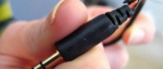
- Prepare the board for soldering, remove protective screens and stickers. Disconnect and remove the coaxial cable.
- Secure the motherboard in the appropriate holder.
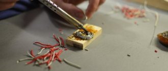
- Remove the compound around the chip being removed. The temperature on the hairdryer is 210 – 240 degrees Celsius.
- Install heat sinks. The installation location of the heat sinks depends on the location of the soldered chip.
- Use a hairdryer to warm up the board for a few seconds. Thus, we increase the temperature of the board so that the flux spreads evenly.
- Apply FluxPlus, or any other no-clean flux, to the surface of the chip.
- Direct a stream of hot air onto the element to be soldered. Temperature during dismantling is 340 degrees Celsius. How can you tell when the solder has melted and it’s time to remove the chip from the board? There are several ways to do this:
- Track time using a stopwatch.
- Count down the seconds to yourself.
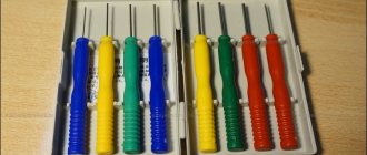
- “Push” with a probe or tweezers the microcircuit itself or the nearby harness (capacitors, resistors or coils). As soon as the chip being soldered begins to move, by a fraction of a millimeter, it is time to place the spatula under or use tweezers.
- Prepare the contact area. For this:
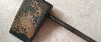
- Use a special spatula to remove any remaining compound;
- tin all contacts without exception with Rose alloy;
- use braid to collect solder residues from the working surface;
- After the motherboard has cooled to room temperature, wash the contact pad with alcohol, BR-2 or DEAGREASER.
- The board is prepared for installation of a working microcircuit.
Soldering chips
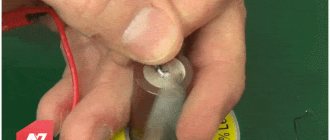
Alloy Rose
To reduce the risk of overheating, Rose alloy can be used. It will help reduce heat to 120 °C. In this way, you can remove the part from dangerous and sensitive areas. Just add a couple of solder granules and a little flux.
After tinning the contacts, the part is easily desoldered. You need to carefully desolder the contacts; they can easily be damaged due to sudden movement.
The resulting solder must be removed from the board. It is very fragile and not suitable for use.
Soldering bga chips
The general principle of soldering is as follows: thanks to the surface tension created when the solder melts, the microcircuit is fixed relative to the contact pad on the system board. Soldering temperature for bga chips on iPhone boards is 320 – 350 degrees Celsius.
Preparing the chip:
- Use a special knife to clean the compound.
- Use a 1 or 2 mm copper braid (depending on the geometric dimensions of the chip) to remove any remaining solder.
- Restore the ball leads. There are two ways to draw conclusions:
- BGA paste is applied through a stencil to the surface of the microcircuit (priority method) Used in most cases.
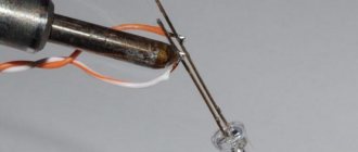
- Manually, with BGA balls. This option is suitable for chips with a small number of pins, up to 50. Although a few years ago, when the quality of stencils left much to be desired), modems on the iPhone 5S were rolled manually. That is, each ball was installed separately using a probe or tweezers. And this is 383 contacts, as calculated by ZXW. If, when distributing balls on a chip glued to a stencil, the balls are not fixed in the holes of the stencil; this means that not enough flux has been applied to the microcircuit.
- If we are working with paste, be sure to warm up the microcircuit with a hairdryer after removing the stencil to form contacts of the correct shape. Additionally, fine-grained sandpaper, P500 GOST R 52381-2005, can be used for these purposes.
- Use alcohol and a toothbrush to finally clean the microcircuit.
- Solder the chip onto the contact pad, installing it along the key and gaps.
- When installing a new microcircuit (purchased from a supplier), a mandatory procedure is to roll the chip onto lead containing solder. This is necessary to lower the melting temperature of the solder and reduce the time the board is exposed to high temperatures.
Soldering bga/BGA soldering
Educational program for beginners
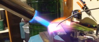
To desolder a part from a board, you need to make sure that the contacts are heated until the solder melts (approximately 230 °C). The main mistake beginners make is to immediately heat the place where they are soldering to 300 - 350 °C.
For example, you need to desolder a microcircuit from a board using a Lukey 702 soldering station.
Many radio amateurs and electronics engineers set heating parameters above 300 °C.
At the first moment, the part is exposed to about 200 °C. The contacts and the surrounding area of soldering work are at room temperature.
The heating of the part reaches 300 °C, but the contacts have not yet reached 200 °C.
The microcircuit experiences a critical temperature of 350 °C. Meanwhile, the surrounding soldering area is heated unevenly, even if the hair dryer is evenly moved across the soldering area. A noticeable temperature difference appears at the contacts of the part.
400 °C and the microcircuit begins to fry.
A little more, and it will unsolder due to the fact that the contacts have practically heated up until the solder melts. But this happens because the board has warmed up. And in this case, it happened unevenly. High temperatures lead to thermal breakdown of the microcircuit and it fails. The board bends, turns black, and bubbles appear due to boiled PCB and its components.
This soldering method is very dangerous and ineffective.
Bottom heating for bga soldering
To reduce the time the board is exposed to high temperatures, the boards are heated. We recommend the monoblock PCB heater STM 10-6. Stable maintenance of the set temperature over the entire area of the heating element contributes to uniform heating of the entire motherboard (depending on the heater model). And one more advantage over other thermal tables is a convenient universal fastening system.
Thermal table STM 10-6
Safe work with semiconductor radio components
Before you unsolder a part from the board with a soldering iron, you need to know the following. Semiconductor elements are extremely sensitive to overheating. Also, tracks on a printed circuit board at high temperatures or when the soldering time is exceeded can peel off from the substrate or break, which is even worse.
Temperature conditions
The temperature of the soldering iron tip should be 200-250⁰С. At higher temperatures, peeling of the printed tracks and overheating of the microcircuit may occur. The same goals are set for the soldering time of one leg - no more than 3 seconds.
Note! Some sites advise for dismantling to focus not on the temperature, but on the power of the soldering iron. It is not right. Their temperatures are the same, it’s just that a less powerful one may not be able to cope with melting the solder at the pin due to intense heat removal, and a too powerful one can easily overheat the pins and the board. The best option is a 40 W soldering iron.
Many microcircuits are sensitive to static electricity. It is necessary to work with an electrostatic wrist strap on and a grounded tool.
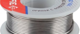
Flux for soldering bga
There are a huge number of flux manufacturers on the market. Bgacenter uses the widely used FluxPlus. You should pay attention to the date of manufacture and expiration date of the flux. Advantages of flux gel:
- no-wash (many professionals recommend washing anyway);
- convenient dispenser, hence high dosing accuracy during soldering work;
- does not emit unpleasant odors;
- ensures good spreading of solder over the base metal, thereby reducing the surface tension of the molten solder.
FluxPlus
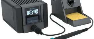
Hot air soldering station
The purpose of the Quick 861DE ESD Lead station is soldering (disassembly and installation) of BGA microcircuits and SMD components. Advantages of this station:
- three memory modes CH1, CH2, CH3;
- high air-to-air performance, Quick 861DE is suitable for soldering circuit boards, phones and laptops;
- temperature stability.
What could be improved in the design of the station is temperature control not with buttons, but with rotary controls, as on the Quick 857D (W)+.
Quick 861DE ESD Lead
Soldering iron
PS-900 METCAL – induction soldering system. A soldering iron power of 60 W is quite enough to work with multilayer boards of modern electronics. Phone repair engineers have 4 years of experience working with this particular soldering iron. What are the distinctive features of the PS-900:
- no need for calibration,
- large selection of tips,
- reliability of the station, the consumable material is the inductor. With daily intensive soldering, the inductor is replaced on average once every 10 months.
Soldering iron
What is needed for work
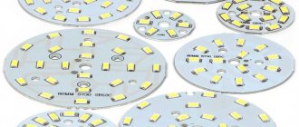
A soldering gun, also called a hot-air soldering station, is a multi-component tool with a large number of functions for repairing modern devices. It allows you to solder SMD components, capacitors, LEDs and other parts. The same applies to BGA-type chips, which make installation more dense. Today, almost every electronic component in modern devices is made in this way.
To solder SMD components, you need the following materials and devices:
- actually, the hair dryer itself;
- attachments for it;
- flux with solder paste;
- copper braid;
- some kind of device for prying up parts (tweezers, for example);
- medium-soft brush;
- lens;
- a soldering iron with a thinner tip compared to a standard one;
- stencil for “rolling”.
To work competently with a soldering gun means to be careful, have angelic patience, and be extremely careful.
Binocular microscope
For a novice phone repairman, the CM0745 microscope is a good option. Binocular microscope with a focal length of 145 mm (with a Barlow diverging lens installed). The purpose of the lens system is to increase the focal length while maintaining the working area.
Advantage of CM0745:
- Smooth increase is achieved using a ratchet.
- The lens system is made of glass, not plastic.
- Possibility to equip the microscope head with different tables and stands.
- Magnification up to 45X.
Microscope for soldering circuit boards