When designing electrical circuits, equipment and electrical appliances, many properties of conductors are taken into account. One of the important properties is capacitance.
This article will describe in detail what the capacitance of a capacitor is. A formula for calculating such a parameter will also be given, the operation of a capacitor in an alternating current circuit and the scope of application of capacitance will be described.
Definition
Resistance is the physical effect of opposing the flow of current through any electrical circuit. All conductors of electric current have this property. This value is measured in Ohms.
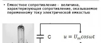
Capacitive electrical resistance is a value through which you can understand that there is a capacitor in the circuit. The capacitance of a capacitor is calculated only for alternating current circuits, without taking into account the presence of resistors in them.
The capacitor is designated in the diagram by the letter “C”, and its capacitance “Xc”.
Video
Coffee capsule Nescafe Dolce Gusto Cappuccino, 3 packs of 16 capsules
1305 ₽ More details
Coffee capsules Nescafe Dolce Gusto Cappuccino, 8 servings (16 capsules)
435 ₽ More details
Best Gaming Keyboards
Principle of operation
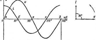
A capacitor with a certain capacity operates on the principle of a period, which consists of charging and discharging an element. The period is divided into 4 parts:
- The first part involves increasing tension. At this moment, the capacitor resistance is minimal and the charging current is very high.
- In the second quarter, its capacity is filled due to the charging current.
- In the third quarter, the capacitor is fully charged, and the current decreases down to 0. The EMF increases with the effect of changing its direction.
- In the last quarter the element is discharged. At this stage, the EMF will be within 0, and the current will gradually increase.
All the processes described in one period determine a further phase shift of 90 degrees.
The nature of the occurrence of capacitance depends entirely on several factors:
- It is necessary to have a capacitor in the circuit.
- Only alternating current should flow through the circuit.
- The conductor resistance must be less than the capacitance of the capacitor.
All these factors help to calculate the most correct value of capacitance characteristics for the most efficient operation of the electrical circuit.
Fazor
Thanks to phase vectors, a complex and time-varying signal can be represented as a complex number (independent of time) and a complex signal (dependent on time). Phasors are divided based on A (amplitude), v (frequency) and θ (phase). This is of great benefit, because the frequency coefficient is often common to all components of a linear combination of sinusoids. In such situations, the factors exclude the optional characteristic and are based only on A and θ.
For example, one can think of A⋅cos (2πνt + θ) simply as the complex constant Aeiθ. Due to the fact that phase vectors are transmitted by magnitude and angle, they are clearly represented by a vector in the xy plane.
The phasor can be viewed from the position of a vector rotating around the origin. The cosine function is the projection of the vector onto the axis. The amplitude acts as the modulus of the vector. Phase constant – the angle formed by the vector and the axis at t = 0
Calculation
The calculation of the electrical capacitance of the circuit is done according to the formula. It consists of the following values:
- "Xc" is the capacitance in Ohms.
- “1” is the period of complete charge and discharge of the element.
- “w” is the circular frequency of alternating current with capacitance, rad/sec.
- “C” is the capacitance of the capacitor, units of Farad.
The formula itself looks like this:
Using this formula, Xc can be easily calculated. To do this, simply multiply the cyclic frequency of the alternating current by a known capacitor value. Next, you will need to divide one period by the resulting value. This way you can always find the resistance of the capacitor in Ohms.
Capacitance can also be calculated using another formula, which is shown in the figure below.
When calculating using this formula, the following dependencies can be traced:
- The capacitance of the capacitor and the frequency of the current are always higher than the resistance.
- The speed of one period of charge/discharge of the capacitor depends on the values of capacitance and frequency.
It is also worth considering that after connecting a capacitor to a DC circuit, its resistance increases greatly. The reason for this phenomenon is explained quite simply - there is no frequency of electricity flow.
Inductor reactance
From the experiment above we can conclude that the coil resistance depends on the frequency and is calculated by the formula
Where
XL - coil resistance, Ohm
P is constant and equal to approximately 3.14
F—frequency, Hz
L - inductance
More details here: https://www.ruselectronic.com/news/katushka-induktivnosti-v-tsepi-postoyannogo-i-peremennogo-toka/
Where
XL - coil resistance, Ohm
P is constant and equal to approximately 3.14
F—frequency, Hz
L - inductance
More details here: https://www.ruselectronic.com/news/katushka-induktivnosti-v-tsepi-postoyannogo-i-peremennogo-toka/
Where
XL - coil resistance, Ohm
P is constant and equal to approximately 3.14
F—frequency, Hz
L - inductance
More details here: https://www.ruselectronic.com/news/katushka-induktivnosti-v-tsepi-postoyannogo-i-peremennogo-toka/
Where
XL - coil reactance, Ohm
P is constant and equal to approximately 3.14
More details here: https://www.ruselectronic.com/news/katushka-induktivnosti-v-tsepi-postoyannogo-i-peremennogo-toka/
P is constant and approximately equal to 3.14
F—frequency, Hz
L - inductance, Henry
Item characteristics
In order to understand what capacitance is, it is necessary to understand its main characteristic, which is called capacitance. Capacity is the storage capacity of an element. It consists in the accumulation of a certain proportion of electric current over a certain period of time. The unit of measurement for this quantity is Farad (F or F).
The element is charged with electricity up to a certain point, after which it begins to discharge and release current further along the electrical circuit. The time for complete discharge directly depends on the value of the circuit resistance. The higher this value, the less time is spent discharging the element. To calculate the capacitance characteristic, the following expression is used:
Capacitors also have a number of additional characteristics. These include:
- Total specific capacitance. It is the ratio of the mass of dielectric plates and capacitive parameters.
- Voltage. The parameter is defined as the operating voltage that the element can withstand.
- Temperature resistance or stability. This is a temperature parameter that does not affect the change in capacitance.
- Insulation resistance. Is the value of the leakage point and self-discharge.
- Equivalent load. A value that defines the loss at the output or contacts of the device.
- Absorption. Potential difference at the moment of discharge to 0.
- Polarity. The parameter is characteristic of elements that operate strictly when a potential of a certain value (plus or minus) is applied to the plate.
- Inductance. The property of a capacitor to form inductive reactance at the contacts. This property can provide the element with the parameters of an oscillatory circuit.
All these values are strictly taken into account when designing circuits or circuits of electrical equipment.
About the charge of a capacitor.
Let's close the circuit. A capacitor charging current will flow through the circuit. This means that some electrons from the left plate of the capacitor will go into the wire, and the same number of electrons will go from the wire to the right plate. Both plates will be charged with opposite charges of the same magnitude.
There will be an electric field between the plates in the dielectric.
Now let's open the circuit. The capacitor will remain charged. Let's short-circuit its lining with a piece of wire. The capacitor will instantly discharge. This means that an excess of electrons will go from the right plate into the wire, and a lack of electrons will go from the wire to the left plate. There will be equal amounts of electrons on both plates, and the capacitor will discharge.
To what voltage does the capacitor charge?
Impedance
In addition to capacitance, a capacitor also has a total resistance or impedance. This value is determined taking into account the values of three parameters: inductive, resistive and capacitive reactance.
The following formula is used to calculate impedance:
The following resistances are used in this expression:
- xL - inductive;
- xC - capacitive;
- R - active.
The active resistance of the circuit appears due to the occurrence of EMF in it. Since alternating current is pulsed in nature, the electromagnetic flux can change quite slightly, and this leads to a shift in the constant value of the emf.
Capacitive and inductive quantities are interrelated. Based on the difference between them, the reactive component of the circuit can be easily found.
From here it is easy to see what the reactance itself depends on:
- If the reactive value is greater than 0, then the device is more loaded with the inductive value.
- If the reactive value is 0, then the capacitance is not loaded with active resistance.
- If the reactivity is less than 0, then the element has high capacitance.
Active resistance is considered an irreplaceable value. It is spent on converting current into another type of energy. The reactive quantity is unchanged for the actual AC circuit.
Active resistance
And we will start the article not with reactance, oddly enough, but with a simple and beloved radio element by all of us - a resistor, which, as they say, has active resistance. It is also sometimes called ohmic. As the wiki dictionary tells us, “active is active, energetic, taking initiative.” The activist is always ready to tear and throw, even at night. He is ready to FULLLY give his all and spend all his energy for the good of society.
The same can be said about other loads with active resistance. These can be various heating elements, such as heating elements, as well as incandescent lamps.
Calculation
Having found out what formula is used to make the necessary calculations and understanding the meaning of capacitance, you can start calculating this value.
For example, let's make a calculation based on the following data:
- Capacitance of the capacitor C=1uF;
- The circuit also has an active resistance R, which is equal to 5 kOhm;
- The inductive reactance of the xL circuit is 4.5 kOhm;
- AC frequency is 50 Hz;
- Voltage 50 volts.
Based on these data, it will be necessary to find the resistance of the capacitor.
We define capacitance as follows:
xC=1/(2πfC)=1/(2×3.14×50×1×10-6)=3184 Ohm or rounded 3.2 kOhm.
To determine the current value in this circuit, we use Ohm’s law:
I=U/xC=50/3184=0.0157 ampere or 15.7mA.
After this, the parameters of the total resistance are determined:
Z=(R²+(xL-xC)²)½=(5000²+(4500–3184)²)½=5170 Ohm or 5.1 kOhm.
According to these calculations, it is possible to determine the influence of the capacitive element on the electrical circuit. The main thing is to understand what physical quantities are used in these formulas to perform correct calculations.
About the charge of a capacitor.
Let's close the circuit. A capacitor charging current will flow through the circuit. This means that some electrons from the left plate of the capacitor will go into the wire, and the same number of electrons will go from the wire to the right plate. Both plates will be charged with opposite charges of the same magnitude.
There will be an electric field between the plates in the dielectric.
Now let's open the circuit. The capacitor will remain charged. Let's short-circuit its lining with a piece of wire. The capacitor will instantly discharge. This means that an excess of electrons will go from the right plate into the wire, and a lack of electrons will go from the wire to the left plate. There will be equal amounts of electrons on both plates, and the capacitor will discharge.
To what voltage does the capacitor charge?
Application
In electronic circuits, a capacitor is very often used as a filter element. In this case, engineers take into account the method of connecting this element:
- When a capacitor is connected in parallel to a circuit, the device is capable of blocking high frequency current. This filter operates on the principle that resistance depends on current frequency. The higher the frequency, the lower the resistance will be.
- When switched on in series, the filter already filters out low-frequency pulses. The second property of such a filter is the ability to prevent direct current from passing through.
Also, a large share of the use of such devices is for audio amplifiers. The capacitor is able to separate alternating and direct current, and therefore work as a low-frequency amplifier. In this case, elements with the smallest capacity are selected.
The devices are also used for DC power supplies or stabilizers. Here the property of separating the constant and variable components is applied. For example, dividing it between consumers using separate outputs for direct and alternating current. In such devices, the capacitor discharges if the load on the circuit is increased by connecting a new device. Thus, the overall ripple in the circuit is smoothed out. If necessary, current of both values can be transmitted through one conductor. This is done as follows - contacts with constant voltage are connected to the terminal of the capacitor for direct contact with alternating voltage. In this way, frequency filtering occurs, pulses are smoothed, and direct current is transferred to the consumer. This circuit is used in antenna amplifiers that are connected to televisions.
About real capacitor
A real capacitor has two resistances at the same time: active and capacitive. They should be considered connected in series.
The voltage applied by the generator to the active resistance and the current flowing through the active resistance are in phase.
The voltage applied by the generator to the capacitance and the current flowing through the capacitance are shifted in phase by 90. The resulting voltage applied by the generator to the capacitor can be determined using the parallelogram rule.
At the active resistance, the voltage Uact and current I are in phase. At capacitive reactance, the voltage Uc lags the current I by 90. The resulting voltage applied by the generator to the capacitor is determined by the parallelogram rule. This resulting voltage lags behind the current I by some angle φ, always less than 90.
Measurement and testing
You can measure the integrity of the capacitor and its resistance using a multimeter. Before this, the element must be disconnected from the circuit.
Examination
Diagnosis of the integrity of the capacitor begins with a visual inspection of its condition. Any cracks, swelling or deformation of the housing can be considered a malfunction of the element. If a visual inspection does not produce any results, then the element is checked for breakdown using a tester.
This check is done as follows:
- The element must be removed from the circuit, and its contact terminals must be shorted with a metal object for discharge.
- Set the multimeter to resistance measurement mode.
- Connect the measuring probes to the contacts of the device.
- The resistance of a serviceable element will be measured at an infinite value, which will exceed the leakage resistance value. The magnitude of this leakage is 2 kOhm.
If the reading is less than this value, then the element is faulty and broken.
Metering
You can also measure resistance using a multimeter. It will need to be switched to the mode for measuring resistances of more than 100 kOhm. Next, you need to connect the probes of the device to the contacts of the device. It will take some time to fully charge the cell. After that, it will show the final result, which should not be higher than 100 kOhm. If this threshold is exceeded, then an unambiguous conclusion can be made that the element is faulty.
Capacitance measurement
To measure capacity, you will need a tester with CX mode. If there is no such mode, it will be impossible to check the element. Next is required:
- Completely discharge the capacitor.
- The CX mode is selected on the multimeter.
- Connect the measuring probes to the contact terminals of the device, strictly observing the polarity.
- The device must show a value greater than 1, but its value must be within the limits of those indicated on the body of the part. If the value is 0 or outside the specified values, then the capacitor can be considered faulty.
The data obtained by the multimeter can also be considered a capacitive value, since at the time of testing the element is charged with current.
Vector diagram of currents in a circuit with a capacitor
To determine the effective value of the total current I using the vector addition method, we construct a vector diagram according to the equation
I = IG + IC
Effective values of current components:
IG = GU (13.31)
IC = BCU (13.32)
The first on the vector diagram is the voltage vector U (Fig. 13.16, a), its direction coincides with the positive direction of the axis from which the phase angles are measured (initial voltage phase φa = 0). Vector IG coincides in direction with vector U, and vector IC is directed perpendicular to vector U with a positive angle. From the vector diagram it can be seen that the total voltage vector lags behind the total current vector by an angle φ, the value of which is greater than zero, but less than 90º. Vector I is the hypotenuse of a right triangle, the legs of which are its constituent vectors IG and IC:
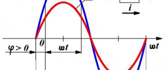
At voltage u = Umsinωt, according to the vector diagram, the current equation
i = Imsin(ωt + φ)
Connection of capacitors
Often a capacitor by itself is not enough. Therefore, such electronic components have to be combined into groups, so-called batteries. With this connection, many containers are connected to each other to obtain a new one with different characteristics.
There are 2 main ways to connect parts:
- consistent;
- parallel.
Series connection of containers
With this type of connection, many parts are lined up in a long chain (from two pieces or more). Most often in practice, combinations of 2-5 parts are used. Each previous one is connected to the next one. The result is a long chain, reminiscent of cars on a train.
Serial connection
Connecting capacitors in series reduces their total capacitance. This is due to the fact that the thickness of the dielectric between the plates of the device increases, while the area of their intersection remains unchanged (see formula above). How to calculate the total capacitance of a capacitor when connected in series can be found in the formula below.
Capacitance of series capacitors
In fact, such a connection is used to obtain a new capacitance value, but such a capacitor is simply not commercially available. For example, having two elements with a nominal value of 10 uF each and connecting them in series, you can get a total capacitance of 5 uF.
Example of sequential calculation
Another feature of series connection is the increase in total voltage. If you take 2 containers of 200 V each and connect them in the described way, then the final battery voltage will be 200 + 200 = 400 volts.
About real capacitor
A real capacitor has two resistances at the same time: active and capacitive. They should be considered connected in series.
The voltage applied by the generator to the active resistance and the current flowing through the active resistance are in phase.
The voltage applied by the generator to the capacitance and the current flowing through the capacitance are shifted in phase by 90. The resulting voltage applied by the generator to the capacitor can be determined using the parallelogram rule.
At the active resistance, the voltage Uact and current I are in phase. At capacitive reactance, the voltage Uc lags the current I by 90. The resulting voltage applied by the generator to the capacitor is determined by the parallelogram rule. This resulting voltage lags behind the current I by some angle φ, always less than 90.