How the device works
To convert one voltage level to another, pulse voltage converters using inductive energy storage devices are often used. According to this, three types of converter circuits are known:
- Inverting.
- Raising.
- Downgrades.
These types of converters have five elements in common:
- Key switching element.
- Power supply.
- Inductive energy storage (choke, inductor).
- A filter capacitor that is connected in parallel with the load resistance.
- Blocking diode.
The inclusion of these five elements in different combinations makes it possible to create any of the listed types of pulse converters.
Circuit of a simple voltage inverter.
Regulation of the output voltage level of the converter is ensured by changing the width of the pulses, which control the operation of the key switching element. Stabilization of the output voltage is created by the feedback method: a change in the output voltage creates an automatic change in the pulse width.
A typical representative of a voltage converter is also a transformer. It converts AC voltage of one value to AC voltage of another value. This property of a transformer is widely used in radio electronics and electrical engineering.
Table - Main characteristics of the voltage converter.
Material on the topic: What is called a trigger in electronics.
Purpose of the device
A device that converts voltage is also called an inverter.
An inverter is an electronic device used to transform the DC voltage supplied to its input into an electrical signal that varies over time with a different amplitude. That is, if a constant signal of 12 volts is applied to the input of the device, then at its output it will be possible to obtain an alternating voltage of 220 volts.
The operating principle of the device is based on the conversion of electrical energy. There are both factory-made and home-made devices, but the principle of their operation is the same. The only difference is in quality - reliability and correctness of the output signal shape.
The circuitry of the devices is based on the use of high-frequency transformers, specialized microcircuits and transistors. According to the type of circuit design, inverters are:
- Bridged - in the circuit diagram of this type of converters, transformers are not used. Typically, devices with a power of up to 100 VA are manufactured this way.
- Transformer - a transformer with a zero terminal plays a key role in the circuit. This circuit is simple, but is usually intended to power devices whose power does not exceed 500 VA.
- Combined - their circuitry uses transistors and transformers. This approach allows you to create converters with a wide power range.
What is a voltage converter
A converter is an electrical device that converts electricity with certain parameters or quality indicators into electricity with other values of parameters or quality indicators. The parameters of electrical energy can be the type of current and voltage, their frequency, number of phases, and voltage phase. According to the degree of controllability, electrical energy converters are divided into uncontrolled and controlled. In controlled converters, the output variables: voltage, current, frequency can be adjusted.
According to the element base, electricity converters are divided into electric machine (rotating) and semiconductor (static). Electric machine converters are implemented based on the use of electrical machines and currently find relatively rare application in electric drives. Semiconductor converters can be diode, thyristor and transistor.
Based on the nature of electricity conversion, power converters are divided into rectifiers, inverters, frequency converters, AC and DC voltage regulators, and AC voltage phase number converters.
Modern automated electric drives mainly use semiconductor thyristor and transistor converters of direct and alternating current. The advantages of semiconductor converters are broad functionality for controlling the process of converting electricity, high speed and efficiency, long service life, convenience and ease of maintenance during operation, ample opportunities for implementing protection, alarms, diagnostics and testing of both the electric drive itself and technological equipment.
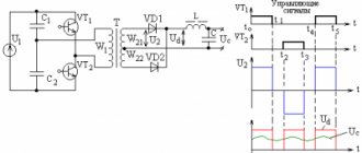
Operating principle of a voltage converter.
At the same time, semiconductor converters also have certain disadvantages. These include: high sensitivity of semiconductor devices to overloads of current, voltage and the rate of their change, low noise immunity, distortion of the sinusoidal shape of current and network voltage.
How are capacitors indicated in the diagram?
Read more
What is the difference between parallel and series connection of resistors?
Read more
Oil transformers - what they are, device and principle of operation.
Read more
Notes
- GOST R 50369-92 Electric drives. Terms and Definitions
- S. Yu. Zabrodin.
Chapter 5 Low-power DC rectifiers, §5.1 General information // Industrial electronics: textbook for universities. - M.: Higher School, 1982. - P. 287. - 496 p.
- S. Yu. Zabrodin.
Chapter 6 Network-driven converters of medium and high power, §6.1 general information // Industrial electronics: textbook for universities. - M.: Higher School, 1982. - P. 315. - 496 p.
- S. Yu. Zabrodin.
Chapter 8 Autonomous inverters, §8.1 Autonomous inverters and their classification // Industrial electronics: textbook for universities. - M.: Higher School, 1982. - P. 438. - 496 p.
| This is a draft article about electricity. You can help the project by adding to it. |
Features of application
At the moment, such equipment is used in almost all industries and every day it is increasingly used in the life of every person, in particular as part of the equipment of cars or trucks. The operating frequency of voltage inverters (voltage converters) does not exceed one hundred kilohertz. Plus, a voltage converter (voltage inverter) can be used as a generator. In principle, a generator and an inverter are quite similar, but you should not assume that these types of equipment are the same in purpose and operating principle.
Boost converter.
There are significant differences in the generator and voltage converter circuits. In addition, compared to a diesel or gasoline generator, a voltage inverter (voltage converter) has a number of advantages, in particular:
- the voltage inverter (voltage converter) has significantly smaller dimensions and weight;
- The voltage inverter (voltage converter) does not need to constantly monitor a whole list of parameters that are mandatory when operating diesel power plants or gasoline generators. These parameters include fuel level, engine oil level and pressure, coolant temperature and level. All these parameters, for example, when operating a voltage inverter (voltage converter) from a car engine are controlled independently, in addition, with relatively low-power consumers (say, up to 1000 W), turning on the car generator for a long time is not required at all and, naturally, no fuel is consumed;
- at idle, the voltage inverter (voltage converter) has a meager energy consumption (about 5 W), in contrast to a diesel or gasoline generator, which at idle consumes up to fifty percent of the consumption at maximum load;
- absence of mechanical wear, respectively, better fault tolerance and longer service life;
- the fluctuation in the output frequency of the voltage inverter (voltage converter) is minimal and, as a rule, does not exceed hundredths of a percent;
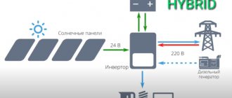
- the voltage inverter (voltage converter) is environmentally friendly (does not make noise and does not emit exhaust gases) and allows you to connect alternative energy sources (for example, solar panels or wind generators);
- a voltage inverter (voltage converter) can be used as a starter-charger, as an uninterruptible power supply, as a battery restorer;
- and, finally, a voltage inverter (voltage converter) is simply significantly (up to several times!) cheaper.
Table - Popular models of voltage converters.
The list of potential users of voltage inverters (voltage converters) can be very wide. Here are producers of various works in remote conditions or with frequent power outages, and lovers of outdoor recreation who want to preserve the opportunity to enjoy the “benefits of civilization”, and prudent owners of various industries or protected objects, etc. and so on.
Material on the topic: Principles of operation of a multimeter and features of choice.
In particular, the use of voltage inverters (voltage converters) in conjunction with various autonomous power sources provides very big advantages; the fuel savings alone are worth it, and there is also a stored “reserve of electricity”, so to speak, just in case.
It will be interesting➡ How to choose a digital-to-analog converter (DAC)
True, when choosing voltage inverters (voltage converters), it is necessary to remember that many consumers of electric current (especially refrigerators and pumps) have a starting power several times higher than the rated power (usually, you can look at the device’s passport) and it is this that should be taken as a basis when calculating the required voltage inverter (voltage converter).
Converter 24V to 12V
The most common schemes
There are several classic standard circuits that are most often used in pulsed-DC converters. They provide different ratios between input and output voltage. These diagrams reveal the very essence of converters and their operating principle.
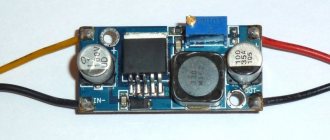
Step-down voltage converter and its circuit
It is used to power consumers whose load is expressed by high currents and low voltage. This is a first-priority circuit that can replace a classic low-frequency converter, in turn, will increase efficiency and reduce the size and weight of the device. The VT transistor acts as an electronic switch; its operation lies between the two modes of misfire (complete closing) and saturation (full opening). Each detail is calculated directly for a specific consumer and voltage source. The main disadvantage of this circuit is the likelihood of breakdown and the appearance of a full large input voltage at the consumer. This will undoubtedly cause the powered device to malfunction.
Boost converter and circuit
It can be used to obtain voltage at a consumer or load greater than the energy sources. It is used for backlighting laptop computer displays and for other electronic devices where it is necessary to make more out of a small voltage. Here the process of appearance of self-induction EMF takes place, which appears after the transistor opens. All accumulated energy in the throttle goes to the load. In this case, the voltage at the inductor terminals changes its polarity.
Inverting circuit
Can be used to produce voltage that has reverse polarity. In this case, the value of U out can be less or greater than U in. The energy that accumulates in the inductor is directed to the load through a smoothing capacitor.
As can be seen from these circuits, they all do not have galvanic isolation, that is, direct isolation of the secondary output voltage from the input.
Here is one such circuit containing a transformer. The energy that accumulates in the magnetic field of the primary winding of the transformer is transferred to the load through the secondary winding. The transformer in this case can be both step-up and step-down. It is used very often in network sources where there is a need to reduce the input voltage from several hundred volts to units or tens.
At the moment when the transistor turns off, the transformer’s inductance can cause a high-voltage jump or surge on the collector, which is undoubtedly very bad and can lead to breakdown of the semiconductor element. For this purpose, an RC chain is installed from a capacitor and an inductor, which can be connected in parallel to the switch or the primary winding. Such a flyback pulse converter is widely used in many network sources of electric current with low power of the order of 100 W.
Another circuit with a transformer and direct connection of a diode is shown in the diagram below.
Used in power supplies of about 250 W. All of these converters discussed above are called single-cycle, because during one conversion period only one pulse will be sent to the load. Their main advantage is the simplicity of the circuit, consisting of just one transistor operating in switch mode, and the disadvantage is the magnetization of the core, which prevents the full use of this magnetic material with maximum efficiency. The transfer of energy to the consumer and the preparation of the transformer for the next demagnetization cycle is carried out with a certain pause, which reduces their output power.
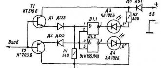
Here are several practical circuits implemented in life, the basis of which is a pulse converter. The first of them has a control element made on a microcircuit, in turn, both circuits are made on field-effect transistors. They are calculated for voltage for loads from 5 to 12 Volts.
Types of converters
When choosing a converter model, you must also take into account the characteristics of electricity consumption by various devices; taking into account the characteristics of consumption, electrical appliances can be divided into 2 groups.
The first group is electrical appliances, when turned on and at the beginning of operation, the short-term power consumption (the so-called peak starting load) is several times higher than the rated power. This group includes, for example, pumps, compressors and refrigerators; to connect them, you often have to use isolation transformers.
Expert commentary
Lagutin Vitaly Sergeevich
Engineer with a degree in Computer Software and Automated Systems, MEPhI, 2005–2010.
Ask a Question
The real power of some devices, for example, pumps based on asynchronous motors and equipment based on them (air conditioners, refrigerators), is approximately 1.5 times greater than the rated power, this is due to the fact that the power is usually indicated without taking into account losses (net power). For devices in this group, it is necessary to select a voltage converter with a maximum permissible power that significantly exceeds the rated power of the device.
The second group is electrical appliances whose starting power does not exceed the rated power, these include televisions, computers, lamps, heaters that consume constant power, as well as tools with commutator-type engines (drills, cutting machines, planes, concrete mixers, lawn mowers, etc.). which consume rated power only when a load is applied, for devices in this group it is enough to select a voltage converter with a maximum permissible power slightly exceeding the rated power of the device.
Electronic voltage converter.
Pulse devices
Pulse converters are used in cases where it is necessary to convert one voltage level to another. Most often they are assembled on the basis of inductive or capacitive energy storage devices. They are distinguished from other power sources by their high level of efficiency, reaching 95% in some cases. Schematic electrical circuits of pulse converters are made using 4 elements:
- switching element;
- energy storage (inductor, inductor, capacitors);
- blocking diode;
- a capacitor connected in parallel with a load resistance.
Combinations of the listed components can form any type of pulse converter. The output voltage is determined by the width of the pulses that control the switching element. This creates a reserve of energy in the inductor. Stabilization is realized through feedback, that is, the pulse width changes depending on the value of the output voltage.
Switching voltage converter.
To create high-frequency currents, converters assembled using oscillatory circuits are used. In this case, the direct current voltage supplied to the alternating voltage generator (multivibrator, trigger) is also the supply voltage. The output pulses are usually rectangular in shape. The resulting alternating voltage can be increased, decreased, etc.
In addition, it is easy to straighten and obtain the desired polarity. To do this, use the appropriate connection of diodes, and the rectifier is assembled, for example, using a bridge circuit. The voltage at the output of pulse converters must be stabilized. For this purpose, various types of stabilizers are used (pulse or linear). True, due to low efficiency, the latter are rarely used.
As for pulse stabilizers, they use pulse width or frequency pulse modulation in their work. In the first case, the duration changes; in the second, the frequency of the pulses changes. There are devices with a combined stabilization method.
Car models
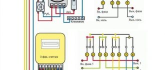
With the increase in the number of cars, the need to use various household appliances during their operation, including those operating on 220V alternating voltage, has increased. For this purpose, automobile inverters were developed, with the help of which the constant voltage from a car battery +12 V (cars) or +24 V (trucks) is converted into alternating 220 V. You can connect an electric razor or electric drill to them, charge a laptop, etc.
A car inverter is a voltage generator whose shape is close to a sinusoid. In this case, the current at the output of the device does not depend on the value of the current at the input and it can be adjusted practically from zero to maximum. In the same way, it is theoretically possible to adjust the frequency and voltage. In a simplified way, the electrical circuit of a car converter can be represented as a transformer, the primary windings of which are supplied with voltage through thyristor switches. Alternately turning on the windings, the thyristors create alternating current at the output of the transformer.
Automotive voltage converters
In this case, a modified (stepped) sinusoid is formed, but this does not in any way affect the performance of most household appliances. Converters for use in cars have a fairly high efficiency, which reaches 90%, which indicates a fairly high quality of the resulting sinusoid. During the operation of the device, the consumer has the opportunity to choose one of three operating modes:
- An operating mode that ensures long-term operation of the inverter at rated power.
- Overload mode, which allows you to get significantly more power from the device than when operating in normal mode. However, in this mode the inverter should not operate for more than 30 minutes.
- The starting mode is used when it is necessary to obtain instant power under high load (starting an electric motor, etc.).
It will be interesting➡ Why do you need a frequency converter
When operating the inverter, it is not recommended to constantly turn it on at maximum power. It is necessary to select its operating mode based on the load size. When choosing a converter for a car, the main attention should be paid to its power. Its value must obviously be greater than the power of the connected devices. In addition, the type of electrical appliances connected is also important. If you plan to connect devices that consume significant currents when starting up to a car inverter, then you need to purchase a device with the appropriate power (from 300 to 2000 W).
Appliances
Currently, voltage converters are widely used in everyday life. They began to be used at home as backup or emergency power sources, the task of which is to ensure the operation of household appliances in the event of an unauthorized shutdown of the centralized power supply network. Typically, a home voltage converter is a combination of an inverter with one or more batteries. In cottages and country houses (dachas), they are also supplemented with devices capable of charging batteries.
Circuit diagram of a household voltage converter.
In some cases, solar panels or wind generators can be used for this. Low-power household appliances are most often connected to inverters intended for home use:
- TVs;
- computers, etc.
In this case, it is necessary to remember about electrical appliances, for example, refrigerators, electric pumps, etc., which require a “pure sine wave” power supply to operate, which requires the purchase of much more expensive devices. In places where there is no centralized power grid, it is possible, by calculating the required electrical power, to organize a power supply system for the whole house. However, this will require the purchase of fairly expensive equipment.
Household voltage inverter.
For example, the cost of an inverter with a capacity of 10...60 kW is at least $20,000. The use of this kind of devices is advisable in the case of organizing power supply systems based on alternative energy sources. If we compare a classic uninterruptible power supply (UPS) operating online with voltage conversion, then the combination of “battery + inverter” components looks preferable for a number of reasons, including:
- gentle operation of batteries;
- large selection of batteries;
- possibility of parallel connection of several converters, etc.
On the domestic electrical equipment market, pulse converters are presented in a fairly wide range. The products of these manufacturers are of high quality and have a large number of different functions. Thus, DC/AC converters provide protection for deep discharge of batteries by controlling the minimum input voltage. They also control the parameters of the output signal.
Additional material on the topic: How to check the battery using one multimeter.
Transformerless devices
Features of a voltage converter from 12 V to 220 V. Recently, they have become very popular, since their production, and in particular the production of transformers, requires a lot of money, because their winding is made of non-ferrous metal, the price of which is constantly growing. The main advantage of such converters is, of course, the price. Among the negative aspects, there is one thing that significantly distinguishes it from transformer power supplies and converters. As a result of a breakdown of one or more semiconductor devices, all the output energy can reach the terminals of the consumer, and this will certainly damage it.
Here is the simplest AC to DC voltage converter. The role of the regulating element is played by the thyristor. The situation is simpler with converters that do not have transformers, but operate on the basis and in the mode of a voltage-increasing device. Here, even if one or several elements fail, dangerous destructive energy will not appear on the load.
Transformerless voltage converters.
The principle of constructing inverters [edit | edit code ]
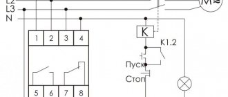
The conversion of the direct voltage of the primary source into an alternating one is achieved using a group of switches that are periodically switched in such a way as to obtain an alternating voltage at the load terminals and ensure a controlled circulation mode in the reactive energy circuit. In such modes, the proportionality of the output voltage is guaranteed. Depending on the design of the switching module (inverter power switch module) and the algorithm for generating control actions, such a factor may be the relative duration of the key control pulses or the phase shift of the control signals of antiphase groups of keys. In the case of uncontrolled reactive energy circulation modes, the consumer's reaction with the reactive components of the load affects the shape of the voltage and its output value.
Voltage inverters with stepped output voltage waveform
The principle of constructing such an inverter is that, with the help of preliminary high-frequency conversion, unipolar step voltage curves are formed, approaching in shape a unipolar sinusoidal curve with a period equal to half the period of change in the inverter output voltage. Then, using a typically bridge inverter, the unipolar step voltage curves are converted into a multipolarity inverter output voltage curve.
Inverters with sinusoidal output voltage
The principle of constructing such an inverter is that, using preliminary high-frequency conversion, a direct current voltage is obtained, the value of which is close to the amplitude value of the sinusoidal output voltage of the inverter. Then this direct current voltage, usually using a bridge inverter, is converted into an alternating voltage in a form close to sinusoidal, through the application of the appropriate principles for controlling the transistors of this bridge inverter (principles of the so-called “multiple pulse width modulation”). The idea of this “multiple” PWM is that during the interval of each half-cycle of the inverter output voltage, the corresponding pair of bridge inverter transistors is switched at high frequency (repeatedly) under pulse-width control. Moreover, the duration of these high-frequency switching pulses varies according to a sinusoidal law. A high-pass, low-pass filter is then used to isolate the sinusoidal component of the inverter's output voltage. . When using a unipolar DC voltage source (levels 0 and Ud are available, where Ud is the DC voltage supplying the inverter), the effective value of the first harmonic of the phase voltage U eff ( 1 ) = 0.45 U d < m >^<(1)>=0.45U_ < m >>When using a bipolar DC voltage source (levels 0, -Ud/2 and Ud/2 are available), the amplitude value of the first harmonic of the phase voltage U m ( 1 ) = 0.5 U d < m >^<(1)>=0.5 U_>accordingly, the effective value U eff ( 1 ) = 0.35 U d < m>^<(1)>=0.35 U_< m >>
Self-excited voltage inverters
Self-excited inverters (self-generators) are among the simplest devices for converting DC energy. The relative simplicity of technical solutions with fairly high energy efficiency has led to their widespread use in low-power power supplies in industrial automation systems and the generation of square-wave signals, especially in applications where there is no need to control the energy transfer process. These inverters use positive feedback, ensuring their operation in the mode of stable self-oscillations, and switching of transistors is carried out due to saturation of the material of the transformer magnetic circuit. In connection with the method of switching transistors, by saturating the material of the transformer magnetic circuit, there is a disadvantage of inverter circuits, namely low efficiency, which is explained by large losses in the transistors. Therefore, such inverters are used at frequencies f no more than 10 kHz and output power up to 10 W. In case of significant overloads and short circuits in the load, self-oscillations fail in any of the self-excited inverters (all transistors go into the closed state).
Operating principle
The voltage converter generates the supply voltage of the required value from another supply voltage, for example, to power certain equipment from a battery. One of the main requirements for the converter is to ensure maximum efficiency. Conversion of alternating voltage can be easily accomplished using a transformer, as a result of which such direct voltage converters are often created on the basis of an intermediate conversion of direct voltage to alternating voltage.
- A powerful alternating voltage generator, which is powered by an original direct voltage source, is connected to the primary winding of the transformer.
- An alternating voltage of the required magnitude is removed from the secondary winding, which is then rectified.
- If necessary, the constant output voltage of the rectifier is stabilized using a stabilizer, which is switched on at the output of the rectifier, or by controlling the parameters of the alternating voltage generated by the generator.
- To achieve high efficiency, voltage converters use generators that operate in switching mode and generate voltage using logic circuits.
- The output transistors of the generator, which switch the voltage on the primary winding, go from a closed state (no current flows through the transistor) to a saturation state, where the voltage across the transistor drops.
- In voltage converters of high-voltage power supplies, in most cases, self-inductive emf is used, which is created at the inductance in cases of sudden interruption of the current. A transistor acts as a current interrupter, and the primary winding of the step-up transformer acts as an inductance. The output voltage is created on the secondary winding and rectified. Such circuits are capable of generating voltages up to several tens of kV. They are often used to power cathode ray tubes, picture tubes, and so on. This ensures efficiency above 80%.
Schematic diagram of a transformerless voltage converter.
Useful properties of the devices
Often, inverters from 12 V to 220 V provide protection or weakening of the functioning of information systems from the quality of AC networks. If there is a sudden power outage, using a spare battery and rectifier will restore backup power and you can shut down your computer without losing essential data.
In complex and critical structures, these devices operate in a longer and more controlled mode. This work is carried out both separately and in parallel with the main electrical network. In addition, the inverter can work as an intermediate link in a converter complex.
A distinctive feature in this case is the presence of a high voltage frequency - up to 100 kHz. For efficient operation, semiconductor switches, magnetic materials and special controllers are additionally used. To be convenient for use, the inverter must have high efficiency, reliability and compact dimensions.
Device repair
Repair of these devices to convert one type of voltage to another is best done in service centers, where the personnel are highly qualified and will subsequently provide guarantees for the work performed. Most often, any modern high-quality converters consist of several hundred electronic parts, and if there are no obvious burnt elements, then it will be very difficult to find a breakdown and fix it.
It will be interesting➡ Why do you need a frequency converter
Some Chinese inexpensive devices of this type, in general, are in principle deprived of the possibility of repairing them, which cannot be said about domestic manufacturers. Yes, they may be a little bulky and not compact, but they can be repaired, since many of their parts can be replaced with similar ones.
Criterias of choice
Criteria that a high-quality pulse converter and stabilizer must meet:
- Continuous operation in extreme moments when the current in the load is maximum;
- Full automation of output voltage regulation. Only then can you not be afraid of overloads or even short circuits;
- High reliability of the device due to high efficiency and, as a consequence, low heat generation;
- Minimum dimensions and weight;
- The presence of galvanic isolation, which excludes even theoretically the very possibility of dangerous input voltage reaching the output contacts, and therefore reaching an unprotected consumer.
A person not familiar with electronics should remember when choosing the right household voltage stabilizer that it must correspond mainly to the power of the devices to which it will be connected. As well as voltage drops and surges that may occur in the network. It is better to choose a stabilizer or a pulse step-down voltage converter with a little power reserve, since the number of consumers used in apartments and private houses is constantly growing.
A simple homemade voltage inverter 12-220V on two transistors
As a transformer I used ferrite cups with the following dimensions: diameter - 35 mm, height - 20 mm. First, the primary winding is wound; it contains 14 turns of wire with a diameter of 0.5 mm; after winding, it must be wrapped in one layer of electrical tape. The secondary winding of the transformer is wound with a wire with a diameter of 0.2 mm and contains 220 turns; we also wrap it with electrical tape in one layer on top. That's it, the transformer is ready, all that remains is to assemble the halves and place them on the bolt.
Using trial and error, I selected transistors for the circuit, focusing on the minimum current consumption of the circuit. The result was a pair of KT814 and KT940, then the resistance and capacitance were selected. As a result of my experiments, I got the following circuit with the indicated denominations, it is shown above. This design of a simple voltage inverter is perfect for powering an energy-saving lamp with a power of 8,9,11 watts. Lamps with a power of 20 watts do not want to work, most likely the secondary is rather weak - I did not redo it. The 9-watt lamp shines as brightly as when powered directly from the 220V AC mains. The current consumption of the voltage converter circuit ranges from 0.5 – 0.54 Amperes.
Interesting read: How to easily check your computer's power supply for faults.
If you use the KT817 transistor and similar ones instead of the KT940 transistor, then the current consumed by the voltage inverter circuit and the lamp increases to 0.86 Ampere. This design of a simple voltage inverter is available for production by all radio amateurs and beginners. The advantages of this design are obvious: ease of manufacture and reliability in operation.
It should be noted that many radio amateurs live in rural areas and do not have the opportunity to purchase imported parts; moreover, although they are inexpensive, the same field-effect transistors cost money, which can immediately burn out or fail if there is an error, not to mention microcircuits. And most often, a radio amateur has limited supplies of radio components. This is how a simple voltage inverter appeared, assembled from parts obtained from Soviet trash. Having a battery with a capacity of 7 Ampere-Hours, it is not difficult to calculate how long it will last - I checked it personally.
Homemade voltage converter.
FAQ
How does the recommended charging current of up to 0.3C affect the battery plates?
For a conventional lead-acid battery, at charge currents of 0.25-0.3 C, an accelerated hydrogen evolution reaction will occur, which will lead to drying and swelling of the battery. In Carbon series batteries, as a result of the capacitive effect and an increase in the number of plates, large currents will be evenly distributed across the plates, which will prevent negative reactions due to the splitting of water in the electrolyte.
Why doesn't the voltage converter work?
Voltage converter malfunctions often occur due to the use of inappropriate wires (for example, aluminum instead of copper). Many inverter models are power sensitive. They are designed to operate only from rechargeable batteries or stabilized power sources. Such devices cannot be connected to solar panels or gas generators.
What difficulties may arise when repairing a voltage converter?
The main difficulty lies in choosing analogs of transistors and transformers in the absence of original components. The remaining elements of the electrical circuit - for example, resistors, capacitors or diodes - do not have design features, so you can use any available parts that are suitable in voltage, power and rating.
Passive limitation without scattering
This is a rather interesting configuration (see Fig. 7), which uses elements of the topologies described above: a demagnetizing winding, a snubber circuit and an active limiter. In this circuit, the capacitor accumulates the energy of the leakage inductance between the primary winding and the demagnetization winding and controls the rate of voltage rise on the power switch when it is turned off, thereby reducing switching losses.
Rice. 7. Passive limiting without dissipation
When the power switch is open, the limiting capacitor is discharged through the demagnetizing winding and releases energy to the input capacitor. Essentially, this is a lossless snubber chain. As the capacitance value Cclamp increases, a quasi-resonant switching mode occurs. Fill factor - less than 0.5.