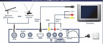
Home > Antennas > Polish TV antenna: description, characteristics and modernization
The television antenna, commonly referred to as “Polish”, has become widespread due to the following parameters:
- low cost,
- large reception range of TV channels (meter and decimeter range),
- receives VHF broadcasts.
It should be noted that the antenna got its name because it was imported into the Russian Federation from Poland; it was often sold disassembled, and before installing it the buyer had to assemble it, this also determined the low cost of the antenna.
Is the Polish grid suitable for receiving digital television?
The Polish mesh antenna at one time quickly spread throughout the country and gained popularity among many users. This equipment is easy to maintain and does not require additional modifications after installation. With the advent of DVB-T2 digital broadcasting in the country, users began to find various amplifiers for this type of antenna, allowing them to capture a digital signal and broadcast it to a TV.
The antenna array itself is broadband. In other words, such equipment is capable of receiving various signals of both meter and decimeter range lengths. This unique property allows the device to catch signals from digital TV channels in DVB-T2 format.
The Polish grid is not the most suitable option used for long-distance reception of digital TV channels. This is primarily due to the fact that the device requires modifications and modernization before it begins to function in the required range.
Main technical characteristics of the Polish antenna
The “Polyachka” range operates from 40 to 800 MHz. This allows you to receive signals and watch TV shows from channels 1 to 20.
With a little modification and connection of the amplifier, it also becomes possible to watch TV channels from 21 to 69. Additionally, the basic configuration of any array antenna model includes its own signal amplification of up to 13 decibels, as well as a characteristic impedance of 300 ohms.
The dimensions of the equipment are relatively small (80x60 cm), weight is 1.5 kg.
The list of antenna components upon purchase is impressive:
- active vibrators (UHF, MV);
- passive vibrators (directors);
- slats for attaching base lines of waveguides and plastic housings;
- mounting an antenna with a reflector;
- reduced voltage units;
- various amplifier models at the buyer’s choice;
- standard plugs for connection.
Coaxial cables required to connect the device to the translator are purchased separately.
How does the Polyachka TV antenna work when receiving a digital signal?
The basic kit does not imply the use of equipment to receive 10 or 20 digital TV channels distributed throughout the country. In any case, until there is an official update to the antenna from the manufacturer, you will have to improve it yourself in order to achieve the required signal level. With proper modification, the Polish array responds well to long-range digital signal reception.
There is a small percentage of probability that, due to the similar signal reception range, the antenna can partially capture the image and broadcast sound even without modification. However, the signal will be weak and difficult to detect on a permanent basis. The standard amplifier that comes with antenna arrays is also not suitable for working with digital television. It needs to be upgraded to improve signal reception quality.
A positive effect is achieved only if the antenna is located close to the repeater tower. In this case, a minimum amount of signal amplification or reduction is required to achieve a high-quality image using standard devices available in stores and electronics markets.
How to install and test the amplifier on the antenna.
[email protected] (spayte) wrote, 2022-10-17 08:01:00 [email protected] spayte 2022-10-17 08:01:00
- Next
- Previous
- Share
Category:
- Cancel
- technique
An antenna amplifier is a device that is installed on the antenna in order to strengthen the signal and, as a result, improve the quality of the picture on the TV screen. It will be especially relevant in areas far from television towers.
As a rule, these are villages and villages located far from civilization.
“> Installing an antenna amplifier is necessary to improve the quality of the signal. Choosing an antenna amplifier There can be many reasons for poor signal reception.
Even residents of large cities face this problem, although it would seem that they are in close proximity to the towers.
The most common causes of interference:
- obstacles located in the signal path - trees, high-rise buildings, etc.;
- landscape gap between the signal reception point and the tower;
- weak signal.
- the signal source is too far from the receiving point;
The choice of antenna amplifier depends on many factors. However, the first thing you need to understand is what kind of antenna is installed.
There are two types: passive and active.
A signal amplifier is already built into the active antenna design by default. If you have problems with the signal, then most likely you have a passive antenna. Such an antenna should only be installed if the tower transmitting the signal is within sight and there are no obstacles between it and the antenna. The next thing to find out is the distance to the nearest tower. TIP.
Depending on the distance to the tower, you should select a device with a suitable gain. As a rule, it is worth buying an antenna amplifier only if the distance from the tower to the house is more than 10 km.
Selecting an amplifier for a Polish array for long-distance reception of a DVB-T2 signal
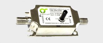
Without an amplifier, the Polish array will not be able to receive and process incoming new generation signals. The base amplifier in the pole antenna is produced separately. In radio electronics stores it can be purchased for no more than 200 rubles.
When choosing an amplifier, it all depends on what signal range the user needs to use for reception. Each radio element of a standard amplifier is fixed using a hinged method to the main part of the antenna. It is there, in the central part of the equipment, that a small secure box is located. Through the board installed in it, you can improve the signal reception effect.
The main task of digital antenna amplifiers is to improve the quality of incoming television signals. Any of the models on the market amplifies received broadcast signals equally well - their quality depends on the distance from the main repeater.
To select a specific amplifier model, depending on the power and distance from the TV tower, you can use the following table:
| Amplifier types | Applicable gain level in dB | Produced noise from the amplifier in dB | Distance from the tower broadcasting the signal, km | |
| Reception of channels from 1 to 21 | Reception of channels from 21 to 68 | |||
| SWA 1 and Lux | 2-14 | 8-23 | up to 2.8 | 3-15 |
| SWA 2 | 15-18,5 | 20-25 | up to 2.8 | 10-20 |
| SWA 3 | 2-6 | 20,5-28 | up to 3.1 | 10-30 |
| SWA 4 Lux | 0-8 | 29-35 | up to 3.0 | 20-45 |
| SWA 5,6,7 | 5-17 | 25-38 | from 1 to 3.9 | 10-70 |
| SWA from 9 to 65 | 9-20 | 21-43 | from 1.9 to 3.1 | 30-100 |
| SWA 555 Lux | 10-15 | 34-43 | 2,2 | 50-100 |
| SWA 777 Lux | 10-13 | 34-45 | 2,3 | 50-100 |
| SWA from 999 to 9999 | 0-52 | 10-54 | from 1.2 to 2.9 | 20-150 |
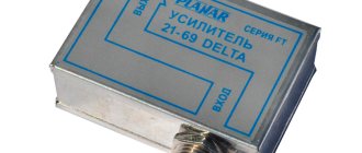
In stores and on the radio market you can find a large number of translators for the Polish antenna. There are dozens of models available for customers to choose from. They all have the same dimensions, but differ in reception quality and signal strength from 30 to 48 decibels.
All amplifier boards, including those for receiving a digital signal, have a voltage of 12 volts, which they receive from reduced voltage supply units 220 to 12 volts. All incoming voltage that goes to the main board located on the antenna passes through a special plug that has a built-in capacitor. With its help, there is a separation between power and incoming signal.
When choosing the right type of amplifier for your array antenna, you can ask your neighbors or see what model they have installed on their roof. Using the table, you can calculate the approximate level of the digital signal that will reach your equipment.
All-Audio.pro
Most audio lovers are quite categorical and are not ready to compromise when choosing equipment, rightly believing that the perceived sound must be clear, strong and impressive.
How to achieve this? Searching for data based on your request: Perhaps the main role in resolving this issue will be played by the choice of amplifier.
The Amplifier function is responsible for the quality and power of sound reproduction. At the same time, when purchasing, you should pay attention to the following designations, which mark the introduction of high technologies in the production of audio equipment:
- Hi-fi. Provides maximum purity and accuracy of sound, freeing it from extraneous noise and distortion.
- Hi-end. The choice of a perfectionist who is willing to pay a lot for the pleasure of discerning the smallest nuances of his favorite musical compositions. Hand-assembled equipment is often included in this category.
Specifications you should pay attention to:
- Signal to noise ratio.
Modern technology assumes a value of this indicator over 100 dB, which minimizes extraneous noise when listening. - Input and output power. The rated output power is of decisive importance, because edge values are often unreliable.
- Frequency range.
Varies from 20 to 20000 Hz. - Dumping factor.
Reflects the output impedance of the amplifier in its relation to the nominal load impedance. In other words, a sufficient damping factor (more than 100) reduces the occurrence of unnecessary vibrations of equipment, etc. - Nonlinear distortion factor. Everything is simple here - the less the better. The ideal value, according to experts, is 0.1%.
It should be remembered: the manufacture of high-quality amplifiers is a labor-intensive and high-tech process; accordingly, too low a price with decent characteristics should alert you.
Classification To understand the variety of market offers, it is necessary to distinguish the product according to various criteria.
Amplifiers can be classified:
- By power. Preliminary is a kind of intermediate link between the sound source and the final power amplifier. The power amplifier, in turn, is responsible for the strength and volume of the output signal. Together they form a complete amplifier.
Important: the primary conversion and signal processing takes place in the preamplifiers.
- Based on the element base, there are tube, transistor and integrated minds. The latter arose with the goal of combining the advantages and minimizing the disadvantages of the first two, for example, the sound quality of tube amplifiers and the compactness of transistor amplifiers.
- Based on their operating mode, amplifiers are divided into classes. The main classes are A, B, AB. If Class A amplifiers use a lot of power, but produce high-quality sound, Class B amplifiers are exactly the opposite, Class AB seems to be the optimal choice, representing a compromise between signal quality and fairly high efficiency.
Possible problems when trying to receive digital TV using the Polish grid
Normally working Polish antennas with an amplifier and power supply may experience the following malfunctions:
- the signal begins to disappear completely;
- when setting up digital television broadcasting, the scale displaying the signal level begins to quickly increase to 100 or, conversely, drops to 0;
- At first there is a reception, but over time it begins to weaken or disappear completely;
- the image begins to slow down, cubes appear, the sound begins to stutter;
- of the 20 channels available for free broadcasting, only 10 are shown - and even then with poor images;
- If the antenna is located at a low height of 2.5-3 meters, then cars passing by it on the road can cause the signal to start to malfunction.
All this leads to the need for modifications to improve the quality of reception and prevent various kinds of problems.
If you are tuning into a digital broadcast and see the level meter rise and fall rapidly, it is being lost. In other words, such a digital signal through the “Pole” is unsuitable for decoding. In this case, modification of the equipment will be required.
All-Audio.pro
Most audio lovers are quite categorical and are not ready to compromise when choosing equipment, rightly believing that the perceived sound must be clear, strong and impressive. How to achieve this? Searching for data based on your request: Perhaps the main role in resolving this issue will be played by the choice of amplifier.
The Amplifier function is responsible for the quality and power of sound reproduction. At the same time, when purchasing, you should pay attention to the following designations, which mark the introduction of high technologies in the production of audio equipment:
- Hi-fi. Provides maximum purity and accuracy of sound, freeing it from extraneous noise and distortion.
- Hi-end. The choice of a perfectionist who is willing to pay a lot for the pleasure of discerning the smallest nuances of his favorite musical compositions. Hand-assembled equipment is often included in this category.
Specifications you should pay attention to:
- Input and output power.
The rated output power is of decisive importance, because edge values are often unreliable. - Frequency range. Varies from 20 to 20000 Hz.
- Nonlinear distortion factor.
Everything is simple here - the less the better. The ideal value, according to experts, is 0.1%. - Dumping factor.
Reflects the output impedance of the amplifier in its relation to the nominal load impedance. In other words, a sufficient damping factor (more than 100) reduces the occurrence of unnecessary vibrations of equipment, etc. - Signal to noise ratio. Modern technology assumes a value of this indicator over 100 dB, which minimizes extraneous noise when listening.
It should be remembered: the manufacture of high-quality amplifiers is a labor-intensive and high-tech process; accordingly, too low a price with decent characteristics should alert you.
Classification To understand the variety of market offers, it is necessary to distinguish the product according to various criteria.
Amplifiers can be classified:
- By power. Preliminary is a kind of intermediate link between the sound source and the final power amplifier. The power amplifier, in turn, is responsible for the strength and volume of the output signal. Together they form a complete amplifier.
Important: the primary conversion and signal processing takes place in the preamplifiers.
- Based on the element base, there are tube, transistor and integrated minds. The latter arose with the goal of combining the advantages and minimizing the disadvantages of the first two, for example, the sound quality of tube amplifiers and the compactness of transistor amplifiers.
- Based on their operating mode, amplifiers are divided into classes. The main classes are A, B, AB. If Class A amplifiers use a lot of power, but produce high-quality sound, Class B amplifiers are exactly the opposite, Class AB seems to be the optimal choice, representing a compromise between signal quality and fairly high efficiency.
What to do if the Polish network does not accept DVB T2?
If “Pole” does not receive DVB T2 and does not respond in any way to manual settings, this cannot be the TV’s fault. Many users believe that the basic gain found in modern plasma and LCD devices is sufficient to access digital broadcast levels. According to many sellers, modern TVs have the ability to receive a signal without connecting antennas. However, in practice it turns out that the further a person is from the signal repeater, the worse the reception becomes.
This state of affairs is especially noticeable in remote areas of the country, which recently switched to digital television broadcasting. Repeater towers have to add amplification so that local residents can achieve the same quality as channels in urban areas.
In many cases, the cause of a poor signal when receiving DVB-T2 is increased power. An incorrectly selected translator can significantly increase outgoing performance, which will lead to interference. There are four ways to correct this problem and achieve better digital TV reception.
In a previous article on this topic, I wrote about why this antenna may not work, namely:
- How its problems manifest themselves
- Why does this happen
- How to eliminate them without removing the antenna - 5 ways
Making the antenna passive - Method No. 1
This method gives excellent results in the area of a good DVB-T2 signal. For example, from a TV tower in my area, at a distance of 25-30 km in line of sight, it catches perfectly.
In addition, the most problematic areas of the array antenna are immediately removed - the amplifier and power supply.
They are simply not needed!
We only need to do two steps!
- We put a regular plug on the cable. No power supply needed!
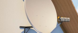
- We connect the cable to the antenna bypassing the amplifier, as shown in the photo
As you can see, the cable is attached directly to the antenna elements.
The amplifier board can be removed, but it can also be left in place; it makes it easier to secure the cable.
The plug must be installed as usual. The long whiskers of the antenna can be cut/broken off to the size of the short whiskers, so they will work in the desired UHF range.
Yes Yes!
I know! Now they will start criticizing me. They say this is unacceptable!
This goes against all the laws of radio engineering! This deprives the antenna of the necessary matching, and so on. Yes! I know! Well, to hell with them, with these laws. I also know that it works. 100%
Well, if you want to do it according to the rules, with approval, then here’s method number two!
Do-it-yourself amplifier repair antenna repair
In detail: amplifier repair do-it-yourself antenna repair from a real master for the site olenord.com. Is the power supply for your television antenna broken?
Don’t rush to the store to buy a new one; this master class will allow you to repair your “original” adapter yourself and use the money you save on more necessary things. Visual signs of a malfunction - the LED in the power supply housing either does not light up at all or periodically goes out. Using a tester, we check the resistance of the primary winding of the mains transformer by connecting the probes of the device to the mains plug of the power supply.
The measurement result should be within 2.5-2.7 kOhm. If there is no circuit, the wire connecting the plug and the transformer may break, but a malfunction of the transformer is more common. Next, we check the resistance at the contacts of the antenna plug to which the power wire is soldered - the device should show the absence of a short circuit.
Unscrew the screws securing the housing cover and remove it. Now unscrew the screw securing the board and remove it. In some models of power supplies, the board is simply inserted into special slots and is not secured with a self-tapping screw.
We check diodes D1-D4. The resistance of serviceable diodes in the forward direction will be 450-650 Ohms, in the reverse direction - to infinity, taking into account the charging process of the electrolytic capacitor.
In our case, all diodes turned out to be serviceable. Now it’s your turn to check the serviceability of the voltage stabilizer chip. Assignment of microcircuit pins (see.
photo): left – power output (12 V), middle – common, right – input (15-20 V). To make the testing process more visual, I soldered a yellow wire to the output, a black one to the general one, and a red one to the last input. Video (click to play).
Naturally, during the repair process we simply connect the tester probes to these points.
We check the voltage supplying the microcircuit. As can be seen in the picture, this parameter is within 21 V, which is normal. Now we check the output voltage.
Here we see that the output voltage spontaneously rises to 18 V, then. . drops sharply to almost zero.
Such jumps occur two or three times a minute, but still more often the power supply does not produce anything at all. Note that this type of failure of an integrated stabilizer is rare; usually there is no voltage at its output.
This is what the already soldered stabilizer chip looks like.
Its marking - 78L12 - indicates that the stabilizer is designed for a voltage of 12 V. Instead, we select the same or similar one with a stabilization voltage of 9-12 V.
It should be borne in mind that with a supply voltage of 9 V, the amplifier will reduce the gain, and increasing the voltage above 15 V may damage the amplifier. We insert a new microcircuit and solder it. We check the voltage at the power supply output - the tester shows 12.1 V.
The power supply repair is almost complete.
We add that if the antenna has been in use for more than two years, it is advisable to check the 100 µF, 25 V electrolytic capacitor.
Making a matching board from an amplifier for a Polish woman - Method No. 2
Of course, you can buy a matching board, ready-made, but I know that they are not always on sale. Yes, you can make it yourself, straight from the amplifier. What will you need for this? Actually the amplifier itself, maybe even a faulty one, a 3 centimeter piece of wire and a soldering iron.
Let's start remodeling
Amplifiers from array-type antennas have a balun transformer, and we will need it to match the antenna with the signal consumer.
In the photo below, the transformer is circled in yellow.
There is no need to solder it, everything is much simpler. (A similar modification can also be made in amplifiers for other types of antennas)
On the amplifier board, from the side of the radio elements, you need to remove everything unnecessary. In principle, you can brush away everything with a soldering iron! - All elements except the transformer and terminals for attaching the cable.
But if you are an esthete, then you can remove just a few elements to turn off everything unnecessary.
Namely, unsolder the capacitor at the output of the transformer (marked with a red dot) and unsolder the strapping elements in the terminal circuit to which the central core of the cable is connected (marked in orange)
Attention! In amplifiers with other numbers, the number of elements and their location may differ, but the meaning remains the same, disconnect the transformer and terminal from the amplifier circuit.
If you find it difficult to figure out which elements need to be removed, make it easier! REMOVE EVERYTHING! EXCEPT A SMALL COIL (matching transformer) AND THOSE PARTS WITH WHICH THE CABLE IS ATTACHED. I only removed what was unnecessary.
This is how I did it! (Photo below) Of course, I washed all solder joints with alcohol. how did you wash it? — Rubbed with a thin layer, you know))) Although this is not necessary.
The final stage
Using a short wire, you need to connect the free output of the transformer to the terminal for the central core of the cable.
That's it, the approval board is ready!
You can install and try. And yes! Don't forget to use a regular TV plug instead of the power supply. The one with the separator from the power supply will not work.
There is no need to supply power to the antenna with such a board.
That's all! Found the post useful? Share with friends, like, subscribe to the channel. Thank you!
Antenna amplifier repair
Seal
Antenna amplifier repairs are usually caused by static electricity (lightning) and power supply failure (overvoltage, which rarely happens).
Damage to the antenna amplifier due to a thunderstorm. Look at the picture of the SWA-2000 amplifier, it shows the transistors involved in amplification and protection (of little help and installed in amplifiers of the 2000 series and higher). During lightning discharges, the transistor of the amplifier of the first stage and the separating capacitor most often fail, see Fig.
rice. When repairing antenna amplifiers in the first stage, it is advisable to install high-frequency transistors with an F limit of 1.5 -2 -3 GHz and a low level of intrinsic noise - Ksh, for example transistors KT391A-2, KT3101A-2, KT3115A-2, KT3115B-2, KT3115V- 2 does not worsen the noise characteristics of most amplifier models, and the use of transistors 2T3124A-2, 2T3124B-2, 2T3124V-2, KT3132A-2 reduces Ksh to 1.5 dB, which improves the parameters of the amplifier. This circumstance allows us to recommend replacing the first transistor of the amplifier with the last ones indicated, even in serviceable but “noisy” amplifiers in order to improve the quality of their operation. In the second stage, you can use cheaper and more powerful transistors KT391A-2, KT3101A-2 and even the KT371, KT372, KT382, KT399, KT316 and others series with a cutoff frequency of about 2 GHz.
If there are difficulties in repairing or purchasing such transistors, then you can put the common KT399, KT316 in both the first and second stages, and there will not be a very noticeable deterioration in the picture. It is better to install new transistors on the opposite side of the board, having previously drilled holes for the leads with a drill with a diameter of 0.5...0.8 mm. It is better to drill so that the hole touches the edge of the platform.
In SWA amplifiers, both transistors operate with a collector current of 10...12 mA. This current is acceptable for the second transistor, but exceeds the permanently permissible one for the first if transistors of the KT3115, KT3124 and KT3132A-2 series are installed. Therefore, after installing a specific instance, it is necessary to set the operating point of transistor VT1.
To do this, microresistor R1 is unsoldered and a trimmer resistor with a resistance of 68...100 kOhm is temporarily connected in its place.
Before turning on the power, the resistor slider must be in the position of maximum resistance so as not to damage the transistor. The amplifier is supplied with 12 V voltage from the power supply and the voltage drop across resistor R2 is measured.
By dividing the measured voltage by the resistance of resistor R2, the collector current is determined. By adjusting the resistance of the tuning resistor towards a decrease, a collector current of about 5 mA is achieved, which corresponds to the minimum noise in the characteristics of the transistors.
Next, instead of a tuning resistor, a constant of the same resistance is soldered in.
After this, the printed circuit board and transistors are covered with a layer of radio varnish or compound to protect them from moisture. How to avoid
all about satellite television
- Equipment Satellite dish
- Toroidal satellite dish
- Satellite tuner - receiver
- DiSEqC switch
- Satellite converter
- C band converter
- Satellite converter feed
- Satellite dish mounting – bracket
- Multifeed
- Multiswitch
- Orthomod satellite
- CAM modules
- Satellite dish tuning device
- How satellite television works
- Selecting a satellite dish
- Installing and configuring a satellite dish yourself
- How to flash a receiver from a USB flash drive
- Null modem cable (RS232) wiring
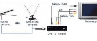
Reception of the T2 TV signal is carried out in the decimeter range and often the antennas that already exist are sufficient for this. The most common is the “Polish antenna” - a grid.
So we will upgrade it to receive T2.
Very often you don’t need to do anything and everything works well - just connect, replace the paid amplifier or throw it away altogether, and connect the cable directly or through an antenna matcher, which allows the signal to pass through the 300 ohm antenna resistance to the 75 ohm cable. and thus increases the strength of the received signal.
Although you can do without this and make a matching loop from the television cable.
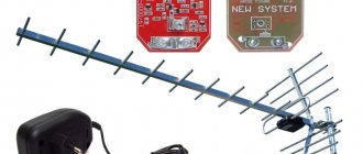
In uncertain reception areas, a more scrupulous approach to antennas for receiving a television signal is needed. And for the Polish antenna a gain board is used.
But to receive T2 you do not need the entire received range that is provided for the Polish antenna. Therefore, it is better to modernize it a little and thereby increase the strength of the received signal.
As you know, such signal amplification boards are short-lived, and with a modernized Polish antenna, sometimes you can dispense with the weak link (amplification board). And thus having done it once, forget it for a long time.
Options for converting a polished mesh to receive T2
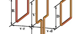
We remove the upper vibrators of the meter range and instead put two rhombuses or bend these mustaches so that the side of the rhombus is 11 - 15 cm (selected empirically and depends on the specific reception frequency).
Reflector - we move the mesh at the back by 10 cm instead of the standard one or completely remove that part as in the figure below (preferably with a mesh).
The second option for redesigning the Polish antenna for T2 reception.
We bend the vibrators as in the figure below and connect them with pieces of aluminum wire. If the vibrators are made of tubes, then the wire can be inserted into them and the edges can be crimped with pliers. For a better effect, vibrators can be shortened to 11-15cm.
And of course, it is better to move the grid back by 10cm.
As an option, replace the entire antenna with a biquad version of Kharchenko with rhombus sides of 11-15 cm in the figure below. And leave only the reflector and an amplifier if necessary.
The presence of passive directors is not necessary and there is no special result from them.
You can write your options for redesigning and modernizing the Polish antenna in the comments.
- Frequencies and channel numbers of digital terrestrial television T2 in Ukraine
- Installation and connection T2
- Repair of T2 tuners typical breakdowns
- Selecting an indoor T2 antenna
Today I want to share the secret of how to connect an antenna, popularly called “Grid” or “Pole” with digital television.
The fact is that this type of antenna does not always work stably with the new DVB-T2 broadcast format. The image may freeze at times, react to passing cars nearby, or the antenna may not work at all. What to do?
How can the “Grid” antenna perform with digital TV?
If you live not very far from a digital television signal translator, then this type of antenna can behave rather strangely.
By default, the Polish antenna is used with an amplifier and power supply. And if, when using such an antenna, provided that all connections are made efficiently, something incomprehensible happens to the signal, for example:
- The signal is completely absent, the antenna does not pick up anything.
- During setup, the signal level scale constantly jumps from zero to one hundred. This can easily be mistaken for a bad connection. But this is not true, it's the antenna.
- There is reception, but at times the signal weakens or disappears completely. The image often “freezes” - freezes for a while, crumbles into cubes, and the sound stutters.
- Out of 20 possible channels, only 10 are shown.
- The signal disappears or weakens when cars pass nearby (if the antenna is installed low and next to the road)
All these are precisely those cases when some alterations will be required.
In my area, at a distance of 25 km from the broadcast tower, “Poles” often behave exactly like this!
TV antenna repair: weak or no signal
If, after turning on the TV, you see only the inscription NO SIGNAL on its screen, it becomes clear that there are problems with the antenna. Also, a poor-quality signal will indicate a malfunction of the antenna (although it may not be the cause).
In many cases, owners of television receivers manage to solve problems with the antenna themselves.
How to properly repair an antenna and when you can’t do without the help of a TV technician? Checking the serviceability of the antenna Depending on the type of antenna connected to the television receiver, television can be:
- analog,
- digital (terrestrial, cable digital, satellite, IP television).
- satellite,
Whatever the type of antenna, if there are any problems with it and poor signal reception, you need to check:
- Is the antenna mechanically damaged?
Another question is the competence of the actions taken and their safety. - How well is the cable connected to the antenna, and is it in the proper position and condition?
- Is the plug inserted tightly and into the correct connector?
- Are the channels configured correctly?
Defects, cable breaks, damaged contacts, corrosion at the antenna connection - all these are malfunctions that need to be eliminated.Are all or some of them configurable?
Note! There may be a separate search for broadcast and cable TV.
Often a new, newly installed TV does not receive a signal. Most often the problem is in the settings, but the possibility of poor quality of the equipment itself cannot be ruled out. If you have been using TV for a long time, first of all double-check that you have not forgotten to pay for TV!
You can always call the operator to double-check the payment and at the same time clarify whether there are any problems with his work. If you are convinced that everything is in order with the antenna and its connection externally and you paid for the TV, it is likely that:
- Some element inside the TV is faulty.
- The antenna itself is faulty.
- The TV tuner is damaged.
- The socket into which the antenna plug is inserted is damaged.
- Software problems.
To repair the antenna, tuner and TV, invite an experienced TV repairman from VseRemont24 to your home! Factors affecting signal quality If channels are shown, but signal reception leaves much to be desired, it is highly not recommended to continue watching. It is unsafe for vision and psyche. Characteristics of a low-quality signal from a faulty TV antenna:
- interference, ripples, noise,
What is the reason for this behavior
So! If you observe anything from the list, then with a 90% probability the reason is that the antenna amplifier is too powerful to receive a DTV signal; in this situation, it does not help, but interferes! The signal is too strong.
Oddly enough, there is nothing good in this, and besides the useful ones, parasitic frequencies, the so-called interference, also increase, which also greatly interfere. Hence the possible interference from cars passing nearby. In the form of a picture crumbling into squares. In other words, the problem is over-amplification of the signal!
All about antenna amplifiers
An antenna amplifier is a device that is installed on the antenna in order to strengthen the signal and, as a result, improve it on the TV screen.
It will be especially relevant in areas far from television towers.
As a rule, these are villages and villages located far from civilization.
Installing an antenna amplifier is necessary to improve signal quality. There can be many reasons for poor signal reception. Even residents of large cities face this problem, although it would seem that they are in close proximity to the towers.
The most common causes of interference:
- landscape gap between the signal reception point and the tower;
- weak signal.
- the signal source is too far from the receiving point;
- obstacles located in the signal path - trees, high-rise buildings, etc.;
The choice of antenna amplifier depends on many factors.
However, the first thing you need to understand is which one. There are two types: passive and active.
A signal amplifier is already built into the active antenna design by default. If you have problems with the signal, then most likely you have a passive antenna.
Such an antenna should only be installed if the tower transmitting the signal is within sight and there are no obstacles between it and the antenna. The next thing to find out is the distance to the nearest tower. TIP. Depending on the distance to the tower, you should select a device with a suitable gain. As a rule, it is worth buying an antenna amplifier only if the distance from the tower to the house is more than 10 km.
If the distance is shorter, then the problem is in an incorrectly selected antenna and the position amplifier will not correct it. Gain is a characteristic that you need to be careful with.
This is a case where more is not better.
If there is a deficiency, the signal will not be strong enough, and if there is an excess, noise will appear, which will still interfere. For this reason, for one type of antenna, many amplifier models with different characteristics are produced. To correctly select the coefficient, you must use a special table.
There is nothing complicated about this. We will not go into the intricacies of the design of the antenna amplifier - for the average person this information will be useless.
Let's talk about two types of amplifiers and their purpose. SWA antenna amplifiers are used in grid-type antennas ASP-4 and ASP-8, which are often called “Polish” antennas.
By themselves, these antennas have a very low gain, and they cannot do without an amplifier. The two most important characteristics when choosing an SWA amplifier will be the gain and noise figure.
When purchasing, pay attention to them.
We have already talked about the first above. With the second it’s still simpler - the smaller the better. This type of amplifier has a very narrow scope. They are produced for repairing failed Locus antennas.
How to make an array antenna reliably receive a DVB T2 digital television signal
Since the reason is over-amplification of the signal, the conclusion suggests itself - the gain needs to be reduced! I’ll tell you five ways to do this without removing the antenna and amplifier.
Attention! Extremely useful advice!
It would be nice to display a signal level scale when “experimenting” with the antenna.
This can be done by pressing the “Info” button on the remote control of the set-top box (usually you need two clicks, sometimes three)
Or you can enter manual search mode and enter the number of the television channel broadcast in your region.
Typically, in this mode, the equipment displays a signal strength indicator. Using this scale you can see the results of fiddling with the antenna. Which is very convenient. By the way, you can find out which channels are broadcasting in your area by following this link.
How to reduce the power of the amplifier without removing the antenna? Five ways!
In order to reduce the power of the amplifier, you need to lower the voltage that powers it.
There are several methods on how this can be done. Choose depending on your situation.
Method one, the easiest
Try simply unplugging the antenna power supply from the outlet and turning off the power to the amplifier. Not always, but sometimes this is enough.
Method two
It is suitable in cases where an antenna power supply with a regulator is used, or one can be installed. Simply turn the knob counterclockwise to reduce the amplifier's power supply voltage. The regulator can change the voltage within the range of approximately two to twelve volts. At the same time, monitor the signal level and choose the best position of the regulator. Please note that changes on the signal level scale will not occur instantly, but with a slight delay.
Attention! To apply the remaining methods described, you must do the following!
Disconnect the standard antenna power supply and install a regular television plug on the TV cable!
The fact is that the plug from the power supply is with a separator and has a separating capacitor inside, it will be superfluous. Therefore, a regular plug!
Method three
You can try removing the power supply to the amplifier altogether. (Like method number one, but only with a regular plug, without a separator, it’s really better to remove it)
- Installing a regular TV plug
- Without any power we connect it to the set-top box/TV.
Sometimes this helps, but not always. It happens that without power, the amplifier does not transmit the signal at all. Or it may not be enough. If it doesn’t work, then you need to supply power to the amplifier, but less than necessary.
How to do it?
Method four
If you use a DVB-T2 set-top box, you can supply power to the antenna amplifier directly from it. For this:
- Don’t forget, install a regular TV plug on the cable.
- We go to the set-top box menu and find the item where the antenna power is turned on. For example: “Antenna Power On/Off”
This feature may be called differently in different set-top boxes, but all models have it. Thus, instead of 12 volts, only 5 volts from the set-top box will go to the amplifier via the television cable. This reduction in nutrition often helps. What should those who don’t use the console do?
Method number five
If you have a TV with a built-in DVB-T2 tuner and you don’t use a set-top box, you can supply 5 volts directly from the TV’s USB port. (but you will have to spend a little)
- Again, you need to install a regular plug.
- You will need to use a special adapter (Injector) to power the amplifier via the USB port of the TV or any charger with USB (approximately 150 - 300 rubles)
These were ways to convert the “Polish Antenna” for digital television, which did not require removing the antenna.
But it also happens that even five volts is too much, over-amplification occurs, and removing the power from the amplifier completely did not help either. (:
In such a case, there is another way, but it involves the need to remove the antenna or get to the place where the amplifier is installed.
This complicates things somewhat, but it is the surest way to adapt a Polish woman to a digital figure. I wrote about this in a separate post.
PS And still I want to remind you about the remaining 10%, which may be due to incorrect installation or other antenna problems. The full version of this article describing possible problems is on my website.
Try it and you will succeed!
That's all! Found the post useful? Share with friends, like, subscribe to the channel. Thank you!
advocatus54.ru
VIRGO wrote: If within sight of the “TV tower”, then practice has shown that it is easier to set the “zero” (SWA-0), this is a permanent balancing trans. without amplifier. Exactly, with a sufficient signal level this is much better.
Not only do hemorrhoids disappear with the failure of the amplifier, but nothing trivially distorts the signal. This is especially noticeable with digital TV - screw amplifiers. Remind me in a personal message if anything happens. PS Instead of “Thank you”, it is customary to press the plus sign () Return to top Message title: Re: How to check a Polish antenna amplifier.
Added: Sun May 17, 2015 16:38:20 Friend Kota Karma: 98 Registered: Fri Jan 23, 2009 20:20:05 Messages: 25893 From: Arya Message rating: 0 Medals: 1 Upgrader wrote: ... This is especially noticeable with digital TV - screw amplifiers.
But here - everything is not so simple! If the DVB-T2 set-top box is connected “analogue”, everything is correct - an amplifier is not needed... We set the tester to 1K. We put a plus on the central input, a minus on the braid. If no current flows, then the plateau is working. In the reverse order, the current passes but with little resistance. On a non-working board, current flows in both directions with little resistance.
Test - review of over-the-air antennas for digital television reception.
Info Antenna amplifier. Principle of operation. Splitters and couplers What is the difference, application options. How to connect a cable and adapter F to a cdma 3g antenna.
DIY digital antenna (for DVB-T2). Antenna amplifiers. Digital TV DVB-T2.
Making a simple antenna.
DIY antenna for digital television DVB-T2. Amplifiers of the LA and LV series. How to make an antenna for digital TV DVB T2 with your own hands.
All-wave television antenna L013.20.
T2 amplifier test, and do you even need it?
How to make an antenna for digital TV with your own hands (DVB-T2).
We set the tester to 1K. We put a plus on the central input, a minus on the braid. If no current flows, then the plateau is working. In the reverse order, the current passes but with little resistance. On a non-working board, current flows in both directions with little resistance. Local antenna repair 1:. How to make your own antenna for DVB-T2 digital television.
Important Do-it-yourself antenna for digital television DVB-T2.
Amplifier replacement. Making a multi-turn resistor.
DIY digital TV antenna.
How to check a capacitor. Attention How to make an antenna for digital TV with your own hands (DVB-T2).
Homemade antennas for a record communication range with 433 MHz radio modules. DMV antenna "Zigzag" type. ✅Homemade Wi-Fi gun?
A powerful antenna for a Wi-Fi signal with your own hands.
T2 amplifier test, and do you even need it? How to connect a cable and adapter F to a cdma 3g antenna. How to quickly make a TV antenna.
Audiophile Club Security Wireless technologies Household appliances Gas equipment Air conditioners Washing machines Refrigerators Video Measurements Tools and technologies Welding Computers and peripherals Medicine and Biology Microcontrollers and digital technology Arduino and K° AVR PIC For beginners MK Monitors For beginners Power Wind power Solar power Power for light sources Programming Radio Radio-controlled models and robots CAD and software Light Power supply for lighting sources Satellite equipment TV - TV Telephony Electronic components Projects and advice Literature and Software Harmful recipes Representative offices of Rohde & Schwarz (Rohde and Schwarz)Club FAQ - FAQ, forum rules Service news RadioLotsman Your suggestions Off topicAdvertisements Buy -Sell WorkDiaries (blogs)File archive Feedback - RadioLotsman - Up Time zone GMT +3, time: 15:59.