The operation of the transformer is based on converting current from a 220 V network. The devices are divided by the number of phases, as well as the overload indicator. Modifications of single-phase and two-phase types are available on the market. The current overload parameter ranges from 3 to 10 A. If necessary, you can make an electronic transformer with your own hands. However, to do this, it is first important to familiarize yourself with the structure of the model.
Model diagram
The electronic transformer circuit for 12V halogen lamps involves the use of a pass-through relay. The winding itself is used with a filter. To increase the clock frequency, there are capacitors in the circuit. They are available in open and closed types. For single-phase modifications, rectifiers are used. These elements are necessary to increase current conductivity.
On average, the sensitivity of the models is 10 mV. With the help of expanders, problems with network congestion are solved. If we consider a two-phase modification, then it uses a thyristor. The specified element is usually installed with resistors. Their capacity is on average 15 pF. The level of current conduction in this case depends on the relay load.
ELECTRONIC TRANSFORMER DIAGRAM FOR HALOGEN LAMPS
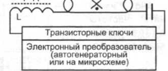
Currently, pulsed electronic transformers, due to their small size and weight, low price and wide range, are widely used in mass equipment. Thanks to mass production, electronic transformers are several times cheaper than conventional inductive transformers on iron of similar power. Although electronic transformers from different companies may have different designs, the circuit is practically the same.Let's take for example a standard electronic transformer labeled 12V 50W, which is used to power a table lamp. The schematic diagram will be like this:
The electronic transformer circuit works as follows. The mains voltage is rectified using a rectifier bridge to a half-sinusoidal voltage with double the frequency. Element D6 of type DB3 in the documentation is called “TRIGGER DIODE” - this is a bidirectional dinistor in which the polarity of the switch does not matter and it is used here to start the transformer converter. The dinistor is triggered during each cycle, starting the generation of the half-bridge. The opening of the dinistor can be adjusted. This can be used, for example, to adjust the brightness of a connected lamp. The generation frequency depends on the size and magnetic conductivity of the feedback transformer core and the parameters of the transistors, usually in the range of 30-50 kHz.
Currently, the production of more advanced transformers with the IR2161 chip has begun, which provides both simplicity of design of the electronic transformer and a reduction in the number of components used, as well as high performance. The use of this microcircuit significantly increases the manufacturability and reliability of the electronic transformer for powering halogen lamps. The schematic diagram is shown in the figure.
Features of the electronic transformer on IR2161: Intelligent half-bridge driver; Load short circuit protection with automatic restart; Overcurrent protection with automatic restart; Swing the operating frequency to reduce electromagnetic interference; Micropower start-up 150 µA; Can be used with phase dimmers with leading and trailing edge control; Compensation for output voltage offset increases lamp life; Soft start, eliminating current overload of lamps.
Input resistor R1 (0.25 watt) is a kind of fuse. Transistors of type MJE13003 are pressed to the body through an insulating gasket with a metal plate. Even when operating at full load, the transistors heat up slightly. After the mains voltage rectifier, there is no capacitor to smooth out the ripples, so the output voltage of the electronic transformer when operating on a load is a 40 kHz rectangular oscillation, modulated by 50 Hz mains voltage ripples. Transformer T1 (feedback transformer) - on a ferrite ring, the windings connected to the bases of the transistors contain a couple of turns, the winding connected to the connection point of the emitter and collector of the power transistors - one turn of single-core insulated wire. Transistors MJE13003, MJE13005, MJE13007 are usually used in ET. Output transformer on a ferrite W-shaped core.
To use an electronic transformer in a switching power supply, you need to connect a rectifier bridge on high-frequency diodes to the output (regular KD202, D245 will not work) and a capacitor to smooth out ripples. At the output of the electronic transformer, a diode bridge is installed using KD213, KD212 or KD2999 diodes. In short, we need diodes with a low voltage drop in the forward direction, capable of operating well at frequencies of the order of tens of kilohertz.
The electronic transformer converter does not work normally without a load, so it must be used where the load is constant in current and consumes sufficient current to reliably start the ET converter. When operating the circuit, it must be taken into account that electronic transformers are sources of electromagnetic interference, therefore an LC filter must be installed to prevent interference from penetrating the network and the load.
Personally, I used an electronic transformer to make a switching power supply for a tube amplifier. It also seems possible to power them with powerful Class A ULFs or LED strips, which are specifically designed for sources with a voltage of 12 V and a high output current. Naturally, such a tape is connected not directly, but through a current-limiting resistor or by correcting the output power of an electronic transformer. Electronic Transformers Forum
Forum for discussing the material ELECTRONIC TRANSFORMER DIAGRAM FOR HALOGEN LAMPS
IN WHAT DIRECTION DOES THE CURRENT FLOW
In what direction does the current flow - from plus to minus or vice versa? An interesting theory about the essence of electricity.
Several working circuits of electromagnetic Gauss Gun are given. The first part of the collection.
What are OLED, MiniLED and MicroLED TVs - a brief overview and comparison of technologies.MEMS MICROPHONES
MEMS microphones are a new quality in sound recording. Detailed description of the technology.
How to do it yourself?
You can easily make an electronic transformer with your own hands. For this it is important to use a wired relay. It is advisable to select an expander for it of the pulse type. To increase the sensitivity parameter of the device, capacitors are used. Many experts recommend installing resistors with insulators.
To solve problems with voltage surges, filters are soldered. If we consider a homemade single-phase model, then it is more appropriate to select a modulator for 20 W. The output impedance in the transformer circuit should be 55 Ohms. The output contacts are soldered directly to connect the device.
Surprises of Chinese economy class power supply circuits.
Servicing another facility with pool control panels. At a rather poor facility, I was surprised to discover that the operational circuit power supply used was not built on a closed modular power supply unit, but on an open power supply unit in a housing. That's why the assembler of that shield had to assemble it with ties at the crossroads to the DIN rail. This is some kind of Chinese NoName HSM-15-12, which safely died and de-energized the control circuits. By the way, from the control circuits it fed only one intermediate relay with 1W power, so the reason for its death at such a low load is unclear to me. There is no desire to replace it with a similar one, so I suggested installing the time-tested modular MeanWell HDR-15-12 at 15W/12V, there should be no problems with such a power supply. Despite the fact that this power supply is cheap in appearance, it is made carefully, stamping and assembly are done at a high technological level. There are no burrs on the aluminum parts; there are various grooves for fixing the board and the perforated cover. During assembly, nothing is warped, and does not play in the hands, the exterior is matte aluminum, the interior is polished. Overall it's nice to hold in your hands.
Not least for this reason, I decided to quickly repair it, especially since the list of breakdowns of such power supplies is banal: - Electrolytes, both primary and secondary power supply circuits. — Power switch of the primary circuit + PWM, or simply integrated PWM with wiring. — In rare cases, the primary of the transformer. — OS optocoupler and/or TL431 chip.
When I opened this power supply, it turned out that it was built on a self-oscillator circuit without PWM chips. The electrolytes of the primary and secondary circuits are swollen, the fuse is intact, the input diode bridge and the key of the primary circuit are intact, and does not show any signs of life when connected.
Having some experience in repairing such products, I did not delude myself with simple repairs. Replaced the swollen capacitors, checked the power switch of the primary circuit, the bridge and fuse are intact. I turned it on through ballast to avoid explosions, if anything happens. The BP showed no signs of life. I decided to check the optocoupler; to do this I need to unsolder it. But then the first “stupidity” was revealed, or more precisely, the deliberate meanness of the design - the optocoupler is located under the power transformer... therefore it is necessary to remove it too!
This is what it looked like after the repair work, which will be discussed below:
Well, “it’s necessary, that means it’s necessary,” I carefully unsolder the transformer and optocoupler. I connect its pins 1-2 to the laboratory device, setting the voltage limit to 1.2V and the current to 20mA. We measure the resistance at optocoupler terminals 3-4 and get 1.2 kOhm (usually about 40-65 Ohms), which means the optocoupler is dead.
Here I made a mistake, being confident that everything was behind me, I soldered the transformer into place and turned on the power supply directly. Thank God, nothing happened, but BP never showed any signs of life.
I had to do something I didn’t want to do within the framework of this project - draw a circuit based on the board model. Since the input circuits had already been checked, I decided to save time and draw only that part of the circuit where there is a lot of wiring and it is not obvious how it is arranged. Somewhere, I slowly began to restore the high side...
But as work progressed, I decided to make a knight’s move. Connect a laboratory device to the output of the power supply, and start raising the voltage to the nominal value to check the secondary circuit. I had just started to increase the voltage when the laboratory technician hit the current limit of 1A. I check the secondary circuit diode - broken! I am replacing the nameless Chinese 3IDQ 100E with a similar body SR560.
Again I give in and increase the tension. Everything is fine, the LED lights up, we don’t need to defend ourselves anymore, but I notice that at 12V the current consumption is as much as 130mA! For a 15W PSU, this is too rough to idle. I feel the board, first of all the ballast resistors, but they are cold. Meanwhile, 1.5W of heat is released somewhere. Suddenly I suddenly burn my finger on the surface of the board, under... the transformer, where there is a soldered optocoupler... and a couple of resistors. But it’s not the optocoupler that’s hot, but the resistor next to it. I turned everything off.
I desoldered the transformer to investigate the causes. I’m starting to sketch out the entire secondary to understand what kind of resistors are there and, in general, how it works.
I check the TL431A chip - it is broken in all directions. This is certainly bad, but it is not yet the reason for power losses of as much as 1.5 W. And then drum roll... the resistance rating in the optocoupler circuit R11 is 100 Ohms, this is at 12 volts of the nominal voltage! And this resistor is hidden along with the optocoupler right under the power transformer! My opinion is that this is some kind of deliberate sabotage. Indeed, if we take the voltage drop across the open optocoupler to be 1.2V, and the TL431A microcircuit to be 2.5V, then we have a current I=(Uin-DUopt-DU431)/R11=(12-1.2-2.5)/100= 0.083A = 83mA (with a burned-out TL431, this current will be higher - 108mA). With the maximum permissible current of the optocoupler being 50mA, it is obvious that it will not last long. I don’t know how long this power supply unit lived at that facility. Judging by the clean body, it was installed not long ago. Therefore, I re-soldered the burnt TL431A and replaced R11 from 100 to 680 Ohms.
Soldered the transformer back into place,
I plugged in the power supply and it worked.
I loaded it with tape and the flight was normal. All!
That's it, that's how it goes. The Chinese don’t just “save money,” but stupidly put a resistor in the OS circuit, which will subsequently cause a whole set of components to fly out. To make it more fun for the repairman, problematic components are hidden under the transformer!!!
At the request of the workers, I add the entire circuit diagram:
Devices with capacitor resistor
The electronic transformer circuit for 12V halogen lamps involves the use of a wired relay. In this case, resistors are installed behind the plate. As a rule, modulators are used of the open type. Also, the electronic transformer circuit for 12V halogen lamps includes rectifiers that are matched with filters.
To solve switching problems, amplifiers are needed. The average output resistance is 45 ohms. Current conductivity, as a rule, does not exceed 10 microns. If we consider a single-phase modification, then it has a trigger. Some specialists use triggers to increase conductivity. However, in this case, heat losses increase significantly.
What is a lamp transformer
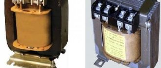
Two types of step-down devices are produced:
- electromagnetic (typical) - operate in accordance with the principle of electromagnetic induction;
Electromagnetic transformer
- electronic - a type of transformer that changes voltage using transistor circuits.
Electronic converting device
The former are only rarely used in private houses or apartments, since they differ in considerable weight and dimensions in comparison with electronic analogues.
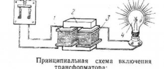
Electronic transformers for the operation of halogen lamps contain semiconductor elements (they participate in lowering the voltage to the desired level). In addition, such devices make it possible to obtain a constant output voltage even in the event of significant fluctuations in the input voltage.
Electronic converter circuit
Step-down transformers from well-known manufacturers have a protection system against overloads and short circuits. The heat generation of such devices is significantly lower when compared with electromagnetic analogues. Some models are equipped with a uniform voltage supply design. The latter increases the life of the light bulbs.
Transformers with regulator
The 220-12 V transformer with a regulator is quite simple. The relay in this case is usually used as a wired type. The regulator itself is installed with a modulator. To solve problems with reverse polarity there is a kenotron. It can be used with or without a cover.
The trigger in this case is connected through conductors. These elements can only work with pulse expanders. On average, the conductivity parameter of transformers of this type does not exceed 12 microns. It is also important to note that the negative resistance value depends on the sensitivity of the modulator. As a rule, it does not exceed 45 Ohms.
Using wire stabilizers
A 220-12 V transformer with a wire stabilizer is very rare. For normal operation of the device, a high-quality relay is necessary. The negative resistance indicator is on average 50 ohms. The stabilizer in this case is fixed on the modulator. This element is primarily intended to lower the clock frequency.
The heat losses from the transformer are insignificant. However, it is important to note that there is a lot of pressure on the trigger. Some experts recommend using capacitive filters in this situation. They are sold with or without a guide.
Models with diode bridge
A transformer (12 Volt) of this type is made on the basis of selective triggers. The threshold resistance of the models is on average 35 Ohms. To solve problems with frequency reduction, transceivers are installed. Direct diode bridges are used with different conductivities. If we consider single-phase modifications, then in this case the resistors are selected for two plates. The conductivity indicator does not exceed 8 microns.
Tetrodes in transformers can significantly increase the sensitivity of the relay. Modifications with amplifiers are very rare. The main problem with this type of transformers is negative polarity. It occurs due to an increase in the temperature of the relay. To remedy the situation, many experts recommend using triggers with conductors.
Model Taschibra
The electronic transformer circuit for 12V halogen lamps includes a trigger with two plates. The model's relay is of the wired type. To solve problems with reduced frequency, expanders are used. In total, the model has three capacitors. Therefore, network congestion problems rarely occur. On average, the output resistance parameter is kept at 50 Ohms. According to experts, the output voltage at the transformer should not exceed 30 W. On average, the sensitivity of the modulator is 5.5 microns. However, in this case it is important to take into account the load on the expander.
Connecting the device to the power supply circuit for halogen lamps
When connecting transformers, it is recommended to adhere to the schematic arrangement of individual light sources when there are more than two of them. In addition, you need to select a suitable location for installing the converter.
Basic connection requirements
The instructions for any transformers certainly contain the main rules; they must not be neglected when performing installation work:
- The step-down device and lamp must be connected to a cable, the length of which does not exceed 1.5 m, and the cross-section is from 1 mm2. Otherwise, the brightness of the lamp will be insufficient, the light will be uneven, and there is a risk of heating the wire.
- If two or more lamps are connected, it is imperative to use a “star” circuit: a separate cable is connected to each lamp. The latter should be the same.
- If the cable length is expected to be more than 1.5 m, then its cross-section increases proportionally.
- The distance to the lamp is at least 0.2 m.
- Correctly calculate the power of the lamps, their correspondence to the step-down electrical appliance.
Attention! It is strictly forbidden to turn on transformers without load.
Installation Requirements
It is permissible to use several schemes for connecting halogen lamps via a transformer:
- One of the simplest: one switch (with 1 key) and a transformer are used. The conductors are attached to the “input” terminals L and N. To connect the lamps at the “output”, copper wires are preferred (minimum cross-section 1.2 mm2). Connection of 12V halogen lamps is parallel.
You might be interested in this Time-current characteristic
A simple diagram for connecting a step-down device
- Dividing the total number of lamps into two equal halves, connecting to different transformers. In the above example, there are 4 lamps of 40 W, the power of 2 is 80 W. Therefore, a 105 W transformer should be used. It is recommended to power a separate step-down device with its own wires. When the latter are connected in the distribution box, this will greatly facilitate possible future repairs. When connecting, it is permissible to use a 1-key or 2-key switch. After completing all the work, the light bulbs can be powered separately. When one transformer fails, you can save money and keep the system running.
Connection diagram for two halogen light bulbs (or more)
Important information! Transformers heat up during operation. Therefore, they need to be installed on surfaces made of materials that are resistant to fire and do not melt.
The service life and reliability of halogen and LED lamps will cover the costs of installing a transformer device. And the protective properties of the latter will ensure a longer service life of such light sources than conventional incandescent light bulbs.
Device RET251C
The specified electronic transformer for lamps is produced with an output adapter. The model has a dipole type expander. There are a total of three capacitors installed in the device. A resistor is used to solve problems with negative polarity. The model's capacitors rarely overheat. The modulator is directly connected through a resistor. In total, the model has two thyristors. First of all, they are responsible for the output voltage parameter. Thyristors are also designed to ensure stable operation of the expander.
Transformer GET 03
The transformer (12 Volt) of this series is very popular. In total, the model has two resistors. They are located next to the modulator. If we talk about indicators, it is important to note that the modification frequency is 55 Hz. The device is connected via an output adapter.
The expander is matched with an insulator. To solve problems with negative polarity, two capacitors are used. There is no regulator in the presented modification. The conductivity index of the transformer is 4.5 microns. The output voltage fluctuates around 12 V.
Repair of switching power supplies
Malfunctions of switching power supplies, repair
Based on the circuit diagram of the switching power supply, we will move on to its repair. Possible malfunctions:
- If the varistor and the fuse at the input or VCR1 have burned out, then we look further. Because they just don't burn.
- The diode bridge burned out. Usually this is a microcircuit. If there is a protective diode, then it usually lights up. They need to be replaced.
- The 400V capacitor C1 is damaged. Rarely, but it happens. Often its malfunction can be identified by its appearance. But not always. Sometimes a seemingly good capacitor turns out to be bad. For example, by internal resistance.
- If the switching transistor burns out, then unsolder it and check it. If faulty, replacement is required.
- If the PWM regulator does not work, then change it.
- Short circuit, as well as breakage of the transformer windings. The chances of repair are minimal.
- An optocoupler malfunction is an extremely rare case.
- Malfunction of the TL431 stabilizer. For diagnostics, we measure the resistance.
- If there is a short circuit in the capacitors at the output of the power supply, then we unsolder it and diagnose it with a tester.
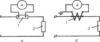
Examples of repair of switching power supplies
For example, consider the repair of a switching power supply for several voltages.
The malfunction was the absence of output voltage at the output of the block.
For example, in one power supply two capacitors 1 and 2 in the primary circuit turned out to be faulty. But they weren't swollen.
On the second one the PWM controller did not work.
All the capacitors in the picture appear to be working, but they have high internal resistance. Moreover, the internal ESR resistance of capacitor 2 in the circle turned out to be several times higher than the nominal one. This capacitor is in the PWM regulator circuit, so the regulator did not work. The functionality of the power supply was restored only after replacing this capacitor. Because PWM worked.
Repair of computer power supplies
An example of repairing a computer power supply. An expensive 800 W power supply came in for repair. When it was turned on, the circuit breaker was knocked out.
It turned out that the short circuit was caused by a burnt-out transistor in the primary power circuit. The repair price was 3,000 rubles.
It makes sense to repair only high-quality, expensive computer power supplies. Because repairing a power supply may be more expensive than a new one.
Device ELTR-70
The specified 12V electronic transformer includes two pass-through thyristors. A distinctive feature of the modification is the high clock frequency. Thus, the current conversion process will be carried out without voltage surges. The model's expander is used without lining.
There is a trigger to reduce sensitivity. It is installed as a standard selective type. The negative resistance indicator is 40 ohms. For a single-phase modification this is considered normal. It is also important to note that the devices are connected via an output adapter.
Model ELTR-60
This transformer features high voltage stability. The model refers to single-phase devices. It uses a capacitor with high conductivity. Problems with negative polarity are solved by using an expander. It is installed behind the modulator. There is no regulator in the presented transformer. In total, the model uses two resistors. Their capacitance is 4.5 pF. According to experts, overheating of elements is observed very rarely. The output voltage to the relay is strictly 12 V.
Switching power supply operation
Primary circuit of a switching power supply
The primary circuit of the power supply circuit is located before the pulse ferrite transformer.
There is a fuse at the input of the unit.
Next comes the CLC filter. The coil, by the way, is used to suppress common-mode interference. Following the filter is a rectifier based on a diode bridge and an electrolytic capacitor. To protect against short high-voltage pulses, a varistor is installed after the fuse in parallel with the input capacitor. The resistance of the varistor drops sharply at increased voltage. Therefore, all excess current goes through it to the fuse, which burns, turning off the input circuit.
The protective diode D0 is needed to protect the power supply circuit if the diode bridge fails. The diode will not allow negative voltage to pass into the main circuit. Because the fuse will open and burn.
Behind the diode there is a 4-5 ohm varistor to smooth out sudden jumps in current consumption at the moment of switching on. And also for the initial charging of capacitor C1.
The active elements of the primary circuit are as follows. Switching transistor Q1 and PWM (pulse width modulator) controller. The transistor converts the rectified DC voltage of 310V into alternating voltage. It is converted by transformer T1 on the secondary winding into a reduced output.
And one more thing - to power the PWM regulator, the rectified voltage taken from the additional winding of the transformer is used.
Operation of the secondary circuit of the switching power supply
In the output circuit after the transformer there is either a diode bridge or 1 diode and a CLC filter. It consists of electrolytic capacitors and a choke.
Optical feedback is used to stabilize the output voltage. It allows you to galvanically decouple the output and input voltages. Optocoupler OC1 and integrated stabilizer TL431 are used as feedback actuators. If the output voltage after rectification exceeds the voltage of the TL431 stabilizer, the photodiode is turned on. It includes a phototransistor that controls the PWM driver. The TL431 regulator reduces the duty cycle of the pulses or stops altogether. Until the voltage drops to the threshold.
Transformers TRA110
These transformers operate from a pass-through relay. The model’s expanders are used in different capacities. The average output impedance of the transformer is 40 ohms. The model belongs to two-phase modifications. Its threshold frequency is 55 Hz. In this case, dipole type resistors are used. In total, the model has two capacitors. To stabilize the frequency during operation of the device, a modulator operates. The conductors of the model are soldered with high conductivity.