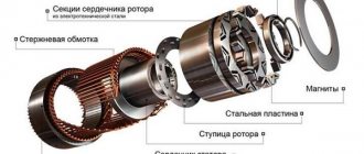
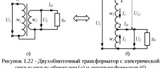
An autotransformer is a type of transformer that has one winding on a multilayer core. It is similar to a two-winding transformer, but differs in that part of the winding is common to both the primary and secondary sides. In the load state, part of the current is transmitted directly from the power source, and the remaining part is transmitted from the action of the device itself. Thus, the device acts as a voltage regulator.
Laboratory autotransformer (LATR)
Design and operating principle
An autotransformer is used to adjust line voltages to either change the value or keep it constant. If the adjustment is made by a small amount, then the transformation ratio is also small, and the currents in the primary and secondary windings are almost the same. Therefore, the part of the winding that causes the difference between the two currents can be made of a much smaller conductor.
The control range, leakage inductance value and overall size (due to the fact that there is no second winding) of the autotransformer with the required amount of reactive or active power is less than that of transformers that have a double winding.
Both windings - primary and secondary - are connected to each other both electrically and magnetically, and also have a common magnetic circuit. Part of the primary winding is connected to the AC power supply. Thus, by simply reversing the connections, supply voltages can be easily increased or decreased.
When the original current flows through one winding in one direction, the current in the secondary winding moves in the opposite direction. The autotransformer has several potential tapping points along the winding.
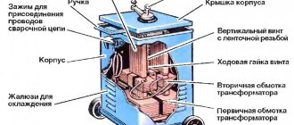
Design of a single-phase autotransformer
Flaws
Before putting the presented equipment into operation, it is necessary to study its main disadvantages:
- A low voltage type circuit will be significantly affected by high voltage levels. To avoid network failure, you will need to create a well-designed low voltage supply system. Only in this case will the device be able to withstand increased loads.
- The flux dissipated between the windings is negligible. If certain faults occur, a short circuit may occur. Its probability in this case increases significantly.
- The connections that are made between the secondary and primary windings must be identical. Otherwise, some problems may occur during the operation of the unit.
- It is impossible to create a system with grounding on one side. Both blocks must have a neutral.
- The presented system makes it difficult to maintain electromagnetic balance. To improve this indicator, you will need to increase the body of the device. If the transformation range is significant, resource savings will be negligible.
It should also be noted that when repairing an autotransformer, eliminating problems and emergencies that have arisen, the safety of the operating personnel may be reduced. Higher voltage can also be observed on the lower winding. In this case, all elements of the system will be connected to the high-voltage part. According to safety rules, this state of affairs is unacceptable. In this case, there is a possibility of breakdown of the insulation of conductors that are connected to electrical equipment.
Having examined the main features of the operation and design of autotransformers, we can draw conclusions about the advisability of using them for our own purposes.
Operating modes
- In autotransformer modes (a), it is possible to transfer rated power from the HV winding to the LV winding or vice versa. In both modes, the series and common windings are loaded with typical power, which is acceptable.
- In transformer modes, it is possible to transfer power from the LV winding to the MV or HV winding, and the LV winding can be loaded to no more than Stype. In these modes, the AT is underloaded, which is acceptable, but uneconomical.
- In combined mode (b), it is possible to transfer power of no more than S type from the LV network to the HV network and at the same time (Snom Stype) by autotransformer from the MV network to the HV network. This mode is acceptable and economical, because the load of the common winding can, in the limit, be equal to 0, and through the AT the total is transmitted Snom.
Also read: Pulse transformer
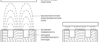
Choosing the optimal operating mode is important for three-phase devices. They are used for continuous parameter adjustment with low losses. This component provides users with the best possible adjustment accuracy with minimal losses and therefore reduced heat generation. For three-phase current, this effect is achieved using mechanical connections of three control transformers. The sliding current collectors are designed in such a way as to ensure reliable output contact and, when triggered, simultaneous cleaning of the contact track. Carbon brushes are used that can rotate or move back and forth.
A variable autotransformer has multiple primary windings to create a secondary voltage that is regulated in the range of a few volts to fractions of volts per revolution. This is achieved by placing a carbon brush or slider in contact with one or more turns of the primary winding. Since the turns of the primary coil are evenly distributed along its length, the output value is proportional to the angular rotation of the brush.
Safety precautions when working with LATR
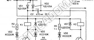
I would also like to add a few words about safety precautions. There are LATRs without galvanic isolation . This means that the phase wire from the network goes directly to the output of such a LATR. The LATR circuit without galvanic isolation looks like this:
In this case, a network voltage of 220 Volts may appear at the output terminal of the LATR with a probability of 50/50. It all depends on how you plug the LATR mains plug into a 220 Volt socket.
If you look closely at the circuit diagram on the front panel of the LATR Resanta, you can see that the “X” and “x” terminals (the two bottom ones) are connected to each other by a conductor.
That is, if there is a phase on the “X” terminal, then there will also be a phase on the “x” terminal! You won’t measure the phase in the socket every time to insert the plug correctly, will you? Therefore, BE extremely CAREFUL! Try not to touch the LATR output terminals with your bare hands!
In principle, I touched it and nothing like that happened to me. The problem turned out to be that I have a wooden floor, which is almost a dielectric. I measured the voltage between me and the phase - about 40 Volts came out. That's why I didn't feel these 40 Volts. If I grabbed the battery with one hand or stood with my bare feet on the ground, and with the other hand grabbed the output “x” of the LATR, then I would be shaken very, very hard, since all the full 220 Volts would pass through me.
Classification of species
Typically, the devices in question are used in industrial and domestic applications that are designed for low power consumption. They are also effective for connecting systems operating at different voltages. This explains the variety of types of autotransformers.
The products in question are:
- According to the degree of external protection of the case - devices intended to operate outside are equipped with a waterproof case.
- According to technical characteristics - operating frequency range, maximum primary and secondary voltage values, maximum secondary current, power and temperature.
- According to the type of electrical network in which they operate - single-phase or three-phase.
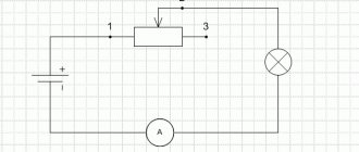
Single-phase (left) and three-phase (right) - Depending on the output voltage, autotransformers can be step-up or step-down. A special class is formed by devices with sliding taps. An important characteristic that is taken into account when choosing is the type of core - laminated, split and toroidal.
1a – transformer, 1b – step-down, 1c – step-up
Main types of autotransformers
- VU-25-B - serves to equalize secondary currents in differential protection of power transformers.
- ATD - power 25 W, takes a long time to saturate, has an old design and is therefore used very rarely.
- LATR-1 - designed for networks with a voltage of 127 V.
- LATR-2 - used with a voltage of 220 V.
- DATR-1 - designed for light loads.
- RNO - designed for heavy loads.
- ATCN - used in measuring television devices.
Peculiarities
The equivalent circuit of the autotransformer allows you to save on the amount of copper conductor. For such equipment, wire of a smaller cross-section is required. This ensures significant savings in materials and a relatively low cost of the device. It is possible to reduce the cost of manufacturing the presented equipment by reducing the amount of steel for the manufacture of the magnetic drive. Power transformers and autotransformers differ significantly in the size of the core cross-section.
The design of a modern autotransformer makes the equipment in demand if the transformation coefficient approaches 1 or is in the range from 1.5 to 2. If the coefficient is greater than 3, the use of such a device becomes unjustified.
In many respects, the operating principle of an autotransformer, its design and parts differ little from conventional two-winding transformers.
Various operating modes of autotransformers can eliminate the shortcomings of the household electrical network. This is necessary, for example, when the voltage does not reach or, conversely, slightly exceeds the standard norm of 220 V. The design features of the autotransformer allow adjustments to be made in certain steps. An electronic autotransformer, which includes a switching and control system, performs this process automatically.
Decoding the main parameters
Windings are usually designated by capital letters (A, B, C, etc.), while the common neutral connection is designated N or n. For secondary taps, digital index numbers are used for all tap points along the primary winding. And indices usually start with the number “1” and continue increasing.
The designation of domestically produced household autotransformers manufactured in accordance with GOST 7518-83 includes:
- Letter indices that determine the class of the device - transitional (APB) or adjustable (APB);
- Reactive power rating, kVA, for which the windings are designed.
GOST 7518-83 provides for the indication of the highest voltage on the secondary winding separately in the absence and presence of an external load.
Separate markings are adopted for laboratory autotransformers - LATRs: after the letter designation the rated power of the device is indicated in kW.
Where are they used?
The main areas of application of the devices are:
- Compensation for potential drop in distribution systems, which is produced by increasing supply voltage values.
- Control systems for asynchronous and synchronous motors, where the presence of an autotransformer with several taps makes starting easier.
- In research laboratories, when it is necessary to vary electrical variables within wide limits.
These devices are also used to adjust the brightness of light; Such devices are called dimmers. In these cases, special attention is paid to the correct selection of fuses, otherwise a higher supply voltage may end up at the secondary terminals.
Tips and tricks
Currently, along with single-phase devices, three-phase devices that differ in winding are also widely used. There are modern three-phase autotransformers with two and three circuits.
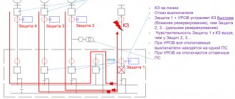
The main protective characteristics of the autotransformer are presented in several options:
- differential type, preventing failure in case of any disturbances in the winding;
- the principle of current cut-off, which corrects problems that arise on busbars or inputs;
- highly efficient current protection, which clearly operates in conditions of damage to the unit;
- gaseous appearance, notifying even of secretions or a decrease in the amount of oily liquid.
Current transformers are an important protective property of the relay type. Current transformer connection diagram - installation options can be found on our website.
Why is a ground wire needed? Let's look at the purpose in more detail below.
The design provides protection in the event of a short circuit or overload, but the device cannot be used if damage to the insulating layer is noticed, there is a failure in the connecting areas, there are extraneous sounds or excessive vibration, and the device has pronounced cracks or numerous chips on the body.