A television antenna, which is made by yourself and is designed to receive a digital signal (DVB-T2), may not be inferior in quality to factory receiving devices. Depending on the task, terrain, operating conditions, a homemade antenna can be made in different ways. The design can be either very simple or performed after calculating a bunch of formulas. If you make accurate calculations, then you can successfully catch two multiplexes on your TV (each with 10 channels, a total of 20 channels will be received on TV).
Antenna efficiency
The antenna will work without an amplifier.
Signal reception is ensured due to the design of the receiver. The form is designed in such a way that you can set up digital TV channels on your TV.
The design is primitive, so to receive an over-the-air signal you need:
- so that the power of the incoming signal to the antenna is at a high level:
- the repeater must be located near your current location;
- there should be no obstacles on the signal path (tall buildings, hills, etc.);
- so that the signal is present at all. There are areas where the digital terrestrial television signal does not arrive at all. Then, no matter what the antenna is, it will not be possible to tune the channels on the TV receiver.
From a cardboard box
Cut 2 flat rectangles measuring 250 by 300 mm from a cardboard box. You will also need:
- food/household foil paper;
- glue;
- copper wire;
- 2 bolts and 2 nuts;
- screwdriver, razor blade;
- cable for TV with plug.
First you need to make 2 rectangles from foil, just like from cardboard. Glue them securely to the cardboard. Remove any remaining glue from the foil.
Using a blade, make grooves for fasteners at the corners of the rectangles. Connect the internal circuit to one groove, and the external circuit to the other. The contacts are fixed with bolts and nuts.
Connect the wire to the TV, move the rectangles apart so that their sides are parallel. Attach them to the base.
Required materials and tools
- Coaxial cable with a resistance of 75 ohms. The cable length is not that important. But it is better to choose the shortest possible cable, since with every meter the signal attenuates. As a result, the TV receives less signal and may have problems displaying channels. There may be freezes, “No signal” messages, or the appearance of squares.
- Use a utility knife or other cutting tool to strip certain parts of the cable.
- Pen or marker for marking cables. The parts that need to be stripped of cable insulation will be marked.
- RF connector with adapter (plugs) to insert the cable into the antenna connector of the TV.
- Pliers. The tool is optional, but will help make the contact more tightly at the last antenna connection.
- Wood (plywood). After manufacturing, the antenna needs to be shaped into a ring (loop). The cable is subject to change in shape due to natural reasons. Therefore, it is better to fix the loop on a wooden frame so that the shape remains unchanged even under the influence of external factors (strong wind).
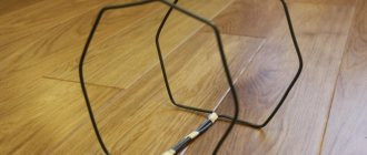
Double-triple square
A double square is a pair of frames connected by 2 arrows. The small frame is called a vibrator, and the larger one is called a reflector. The 3rd square is called the director. The manufacturing algorithm for such a device is as follows:
- The metal arrow located on top should unite the centers of all frames.
- The boom located below is made of materials that do not conduct current (wood, textolite).
- Place all the squares so that their centers are on the same line.
- The line must be directed to a ground station.
- The vibrator circuit must be open. Its edges are fixed on a textolite plate.
- The mast is made of wood.
Taking into account the fact that the frame is symmetrical and connected to an asymmetrical antenna wire, it is necessary to use a matching device. The best option is a short-circuited loop. It is made from parts of coaxial wire. The section on the left is the feeder, on the right is the cable. A wire is fixed at the junction of the feeder and the cable, which is then connected to the TV.
The cable is cut on one side by removing the aluminum screen. The braid must be twisted into a bundle. Cut the main conductor down to the insulating layer. The feeder also needs to be cut. Pull out the aluminum screen and twist the braid. There is no need to touch the main conductor.
After that, follow this algorithm:
- Solder the edge of the vibrator located on the left with the braid of the cable and the feeder conductor.
- Solder the edge of the vibrator located on the right with the feeder braid.
- Connect the cable braid to the feeder end located below using a metal jumper. You can also use metal wire.
- The wire parts must be placed in a parallel manner. The distance between them is 5 cm. Special clamps made of non-conducting materials are used. In addition, you can attach a matching device to a PCB plate.
- The wire that is installed in the TV connector must be soldered to the bottom of the feeder. The braids are combined with each other, just like the main conductors.
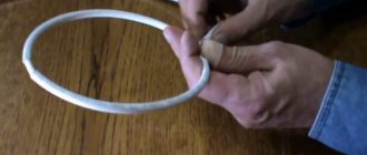
Making a “loop” with your own hands
The manufacturing process consists of several stages:
- cable marking (marks are made at exact distances so that stripping can be done later);
- short circuit of the antenna cable at the end stripping point;
- Installing an antenna plug to connect the cable to the antenna input of the TV.
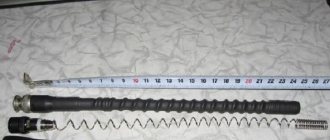
How to mark the cable
- From any free end of the cable, the first mark is made after 5 cm.
- Then another 22 cm is measured and a 2 cm section is marked.
- Then a centimeter section is again marked at a distance of 22 cm from the last mark.
Marking scheme
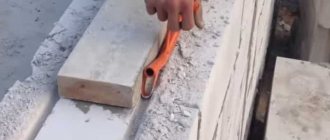
Proper stripping
- The first 5 centimeters of the cable are completely cleared of insulation. Both the external insulation and the internal one, which protects the core, are removed. A connection (twisting) of the shielding layer with the core is made.
1
2
3 - In the second section, the outer insulating layer along with the shielding layer is removed.
It is important to be careful not to damage the internal insulation. In the future, damage to the insulation may cause the inner core to break.
- In the third section, only the top insulation is removed, the screen is not touched.
Next, the first stripped section is screwed onto the last one. Twisting is done by hand. Additionally, you can use pliers to press the contact.
Afterwards we try to give the shape of the loop as accurately as possible.
By the way, the antenna was called “loop” because of its shape.
RF Connector Installation
The cable is connected to the antenna connector of the TV receiver through an adapter. It, in turn, is screwed into the RF connector. The latter must be correctly placed on the other end of the cable.
- Remove the top layer approximately 1 cm long.
- We bend the foil layer and copper braid back onto the cable itself.
- The internal insulation is removed. You can remove it completely by the same 1 cm, but it is better to leave at least 2-3 mm to prevent the screen from shorting to the cable core.
- Screw the connector onto the cable. If it is difficult to do this with your hands, you can carefully clamp the connector with pliers and screw it on. Be careful, as modern connectors are made of brittle metals. There is a high risk of the metal cracking. You'll have to buy a new connector.
- The connector must be inserted so far that the cable core is fully visible (refer to the figure below).
- An adapter is screwed into the connector using a thread. It will be inserted into the antenna input on the television receiver.
We use beer cans
A do-it-yourself dacha antenna made from beer cans is the simplest and most affordable passive type design. It can be done quickly and without basic skills. At the same time, it copes well with receiving UHF broadcasts.
To assemble an antenna from beer cans you will need:
- cable of sufficient length;
- aluminum cans (for the simplest design, 2 are enough);
- 2 bolts or self-tapping screws;
- plug (F - connector) for connecting the cable to the TV;
- electrical tape or tape;
- a base made of wood or plastic for attaching cans (you can use wooden coat hangers).
The antenna circuit is simple:
- Each can is attached with electrical tape or tape to the base pin at a distance of 7 cm from each other.
- The cable is stripped on one side. They are spread out and attached to the rings of the cans or to screwed-in screws. It can also be soldered. A plug is attached to the free end.
This simplest design is suitable for installation both indoors and outdoors. When used externally, the jars are covered with a large plastic container with the neck and bottom cut off. The cable is pulled through a hole made on the side, which can be sealed using boiling water. The finished receiver is connected and configured through automatic channel search.
You can also make an analogue of a satellite dish with your own hands. For this purpose, use a simple umbrella. You will also need:
- aluminium foil;
- copper cable;
- 1 tin can;
- amplifier and power supply for it.
Do-it-yourself TV antenna from beer cans
Operating procedure:
- Measure the umbrella segments between the spokes and cut out elements corresponding to these dimensions from foil. They are sewn to the dome of the umbrella, covering its entire interior.
- A TV signal receiver is installed at the focal point of the metal grille. The amplifier will be a core from which 4 cm of braiding has previously been removed, and a cable screen that protects against interference.
- An oval is cut out of an aluminum can. A hole is made in the center of it, through which a bare wire is passed and a contact is soldered. To protect against oxidation and corrosion, the joint is covered with plasticine.
- The amplifier is powered through a cable.
- The receiver is attached to the handle of the umbrella with tape so that it does not touch the metal. This will protect against interference and distortion. The junction must be sealed with plasticine.
- The power supply is placed next to the TV, and the antenna is turned towards the repeater.
- Channels are established by driving the dish until the best signal is obtained.
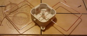
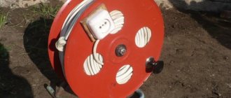
Frame manufacturing
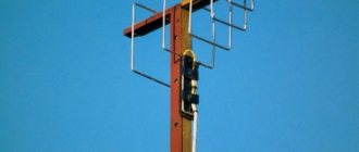
If the antenna will be installed outside the building (on the street), then you need to build a frame. It will maintain its loop shape even when the antenna is exposed to strong winds.
You can make a frame by cutting out a ring in a similar shape to the antenna from plywood or any other material. The cable is then secured to the ring with electrical tape, tape or clamps.
You can also attach a mast - a long stick - to the frame to secure it on the street.
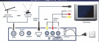
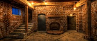
Setting up TV channels
After the coaxial cable antenna is made, installed and connected to the TV, you can start setting up digital television.
Settings are performed differently on different brands of TVs. But the principle of searching for channels is the same everywhere. You need to go to the channel settings menu and perform an automatic or manual search.
Before setting up, be sure to go to the manual setup item and look at the signal level scale. If the signal is weak, try playing with the antenna, placing it in a different place, raising it higher, or changing the direction.
Example of a scale on a Samsung TV
For the most accurate direction of the structure to the nearest TV tower, use the terrestrial digital television map (karta.rtrs.rf). Enter your area and house number in the search bar. Click on your home and a table of repeater characteristics will appear. Look at the compass icon. When directing, be guided by it. This way you can receive the signal most accurately.
In most cases, automatic tuning of air channels will help. If the antenna shows only 10 channels out of 20, this may indicate the following:
- There is only one multiplex broadcasting in your area. This means you can only watch 10 channels.
- The signal is very weak, so only one of the channel packages (multiplexes) is caught. In this case, a more powerful antenna will help. Some options you can do yourself. But it’s better to take a closer look at factory antennas with a built-in amplifier.
After auto-search, if not all channels are shown, try searching manually. Then you need to find out the TVC (television channel) numbers or multiplex frequencies. All data is taken from the ECTV card.
Next, search for each multiplex one by one.
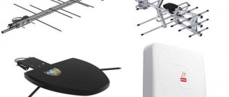
Device characteristics
A television antenna is a bipolar device capable of emitting and receiving signals in the meter and decimeter ranges. Modern digital television requires accurate calculation of wavelength indicators, since only in this case is it possible to obtain a high-quality signal.
An analog antenna will pick up any wave, even the weakest one, while a digital one will require a clear, stable signal.
Modern TVs are capable of monitoring the level of digital signals themselves. For other devices you will need to calculate everything yourself.
Currently, television can operate at any frequency and on waves of different lengths. In order for a digital antenna created by yourself to function efficiently, it is necessary to adjust its waves in accordance with the transmitting station.
To do this you will need:
- Calculate the wavelength for each package of television channels;
- Determine the maximum wavelength that has the shape of a sine wave;
- Calculate half the length of the wave cross section.
The calculation is made using the formula: L = 300 / F. Where L denotes the length and F the frequency.