Every electrician knows how to use a multimeter, but an ordinary person may also need to use this device. If you need to clarify the serviceability of house wiring, radio components, find out how much electric current a particular household appliance consumes, what is the current strength in the network or its voltage, information about simple measuring manipulations with a multimeter will come in handy.
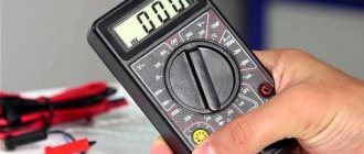
Multimeter ready to use Source bzns.media
Voltage and multimeter
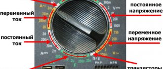
Let's see how to measure voltage with a multimeter. First of all, you need to check the location of the device toggle switch. To prepare the device for measuring voltage, you need to turn it from the off position (indicated as “OFF”) to the V~ mark (the English letter “V” and a wavy line indicating alternating voltage). On some multimeters this mode is abbreviated “ACV”. AC Voltage Test Steps:
- Install the red probe into the socket marked “V/Ω” or “VΩmA” (this is the positive potential), the black one into the “COM” socket.
On a note ! Since alternating voltage has no polarity, installing the probes into the precisely indicated connectors does not play any role. But if the black probe hits a phase, then the number on the screen may be negative.
- Check the switch (it should be at the V~ mark).
- Setting the test level (if you plan to measure alternating voltage in an electrical network with a nominal value of 220 Volts, you should set the test level to a slightly higher value, for example, 236 V, or perhaps to the maximum).
- Inserting the probes into the socket, for the voltage in which it is necessary to check.
Numbers indicating the desired alternating voltage will appear on the screen of the electronic multimeter.
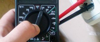
Dial multimeter in the off state Source img1.bgxcdn.com
Next, we'll look at how to use a voltage tester to check battery voltage. To measure DC voltage with a dial or electronic multimeter, insert a red and dark probe into the “V Ω mA” and “COM” sockets, respectively, then turn the switch to “V-”.
After setting the verification level (you will need to set it, as in the previous example, to a slightly larger digital value than the intended measurement object has). The two free ends of the probes must be connected to the object being tested (for example, to the two ends of a battery), observing the polarity (“+” and “-”).
On a note ! If you make the wrong polarity, the multimeter will show a negative value, but the value itself will be the correct number; you need to swap the probes on the battery so that the polarity is correct.
If a value with one or two zeros in front, but without a comma, appears on the device screen, it means that the test level was set too high. It is necessary to achieve a normal number by gradually reducing it and taking measurements. For example, for a battery the value “008” may first appear, and after the indicated manipulations - “8.9”. This means that the battery voltage is approximately 9 Volts.
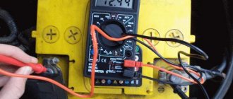
The multimeter shows the battery voltage Source masteram.com.ua
When “1” appears on the screen, the pre-selected measurement threshold may be too high, then it needs to be brought to a suitable value by gradually decreasing it.
Useful tips
- It is necessary to check the power charge at least once every 10-14 days;
- Discharged simple cells cannot be charged or disassembled - the substances inside them, although not as caustic as those of the battery with which the car is equipped, are still unsafe for health;
- Cells that have become unusable must be removed from the battery compartments before they lose their seal and “leak.” An element that is starting to leak can be easily identified by looking at its positive pole - smudges and oxide deposits begin to appear near it.
- Used items should not be thrown away with regular household waste; everyone in the household should be aware of this. They should be thrown into special containers, often installed in large stores and supermarkets.
Rechargeable batteries
Thus, knowing how to check the battery charge, you can not only promptly change dead batteries, but also prevent leakage of caustic electrolyte and damage to various equipment parts.
Checking the current strength
Let's see how to use the tester to find out the current strength:
- Insert the red connector into the socket marked “mA” (“VΩmA”), the black one into “COM” (to check the current strength, the value of which does not exceed 10 Amps). To check the current, which ranges from 200 milliamps to 10 amperes, you should put a red electrical probe into the “10A” connector.
Different positions of drills to determine small and large currents Source www.sciencebuddies.org
- Place the switch on the “A~” mark to check the alternating current value or on the “A-” mark to check the direct current strength.
- Set the measurement range so that it is greater than the expected current strength, but not by much.
- Connect the load (for example, an incandescent light bulb with a socket) into the assembled electrical circuit from the outlet to the multimeter.
Important ! You cannot touch the circuit elements that are not insulated with your hands and the ends of the probe.
- Attach a piece of wire to the lamp base, and the other end to the probe.
- Take another wire and attach it according to the “lamp base - electrical outlet” diagram.
- The red probe (its free end) must be set to the “+” of the object being measured, and the black probe must touch the next element of the circuit (the wire coming from the “load”, that is, from the light bulb).
Remember ! For correct, and most importantly, safe measurement of current, it is necessary to connect the multimeter to the electrical circuit in series, since in ammeter mode the resistance of the multimeter circuit is minimal and if connected in parallel there will be a short circuit.
Connection diagram for a multimeter with a “load” Source electrikmaster.ru
See also: Catalog of companies that specialize in electrical and heating systems
A multimeter can also be used to determine the amount of AC current consumed (for example, for a household appliance). After installing the switch on the direct current symbol (“A-”), you should arrange the probes as follows: for high current - the extreme left position (o), for low current - the middle position (o).
Having set the measurement range approximately corresponding to the current, but slightly larger, you can proceed to the next stage, not forgetting that the device can only be turned on in an open circuit (as in the previous example).
Instrument calibration
It is a set of actions aimed at establishing the relationship between the actual size of the measured characteristic and the readings of the measuring device used to measure it.
That is, calibration is performed when there is doubt that the multimeter reflects the actual value of the measured electrical characteristic. In this case, the results of his work become unreliable.
In order to carry out calibration on your own, you need to carefully study the instructions supplied with the device. Some models are equipped with a countersunk adjusting bolt that allows adjustments to be made without opening the housing.
If this is not possible, you will have to carefully open the case and, after studying the circuit, find the adjustment coil on the board, which is not always easy for an amateur.
For calibration, you will need a reference device, which can be a high-quality expensive multimeter or other device with high measurement accuracy. By comparing the readings of the reference and the device being tested, calibration is performed.
If you are not strong in electrical engineering or do not want to ruin an expensive multimeter, you should contact a metrology laboratory, where your tester will be calibrated according to all the rules.
Knowing how to check the operation of a multimeter, you will always have a device at hand that will help you understand the condition of your home electrical network, household appliances, and car.
Multimeter and resistance
To find out the resistance of any radio component, use a conventional multimeter. Measurement algorithm:
- Insert the probes (black – into the “COM” socket, red – into the socket marked “V/Ω” or “VΩmA”).
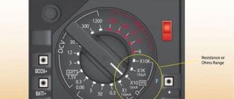
- The switch will need to be moved to the “Ω” position.
- At the third stage, it is advisable to check the serviceability of the device by connecting the two remaining free ends of the probes. The multimeter is working if it shows a zero value.
- Set the measurement limit to the expected approximate average value (for example, 2 M).
- Connect electrical probes to the coil (to the measurement object).
What will be the coil resistance? Source cdn.sparkfun.com
- Look at the display (screen) of the device.
If several zeros appear, the coil has resistance, but the measurement limit will need to be lowered slightly to see the actual digital resistance value. The same must be done when a number appears in front of the numerical value on the electronic multimeter, but with a zero (zeros) at the beginning. If a unit occurs, it is worthwhile, on the contrary, to reduce the set denomination.
Testing with a multimeter
The multimeter has several more functions, one of which is the so-called continuity test. It is used to search for a break in the neutral wire in an electrical circuit.
Algori:
- connect the red probe to “V/Ω”, the black one to “COM”;
Testing wires with a multimeter to check their integrity Source avatars.mds.yandex.net
Checking radio components
If a radio amateur has a digital multimeter, he must know how to use this device to test the functionality and measure the characteristics of transistors, diodes and capacitors. Everything is very simple here:
A black probe should be installed in the COM socket, and a red one in the VΩmA socket.
The black probe (its second end) must be connected to the cathode of the diode (to the “minus”) of the part being tested, and the red one, respectively, to the cathode of the anode (to the “plus”).
The resistance of the part will be displayed on the screen.
If in any position (as in the described algorithm or with the reverse arrangement of the probes connected to the anode and diode) one is displayed, this means that the part has burned out. If the reading is less than one, the diode is broken.
Video description
You can see more details about how this test is carried out in the video:
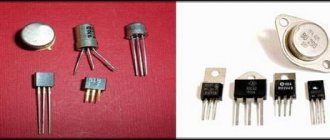
To check the transistor, you need to switch the multimeter to the “hfe” mode and combine the three outputs of the part with the connectors on the device. They are called "B", "E" and "C" and correspond to the "base", "emitter" and "collector" on the transistor. If the connection is correct, the gain value of the radio component being tested will appear on the multimeter screen.
So, how to use a multimeter tester to check the capacitor for its capacity: this part must be inserted into the corresponding connectors on the device (the “CX” sector). By twisting the toggle switch, you can adjust the measuring limits to the required numerical value.
How to check current leakage on a used car with a multimeter
The check includes:
- Turn off the engine, remove the key. Close the doors, but open the windows - the battery will not work continuously, and the car may be locked with a central lock.
- Make sure that the additional lighting and radio are turned off.
- Remove the negative terminal from the battery.
- Place one probe between the negative terminal and the negative terminal of the battery - the device will show the leakage current value.
The normal value is 15-70 mA. If the numbers are higher and you and the seller have time, try to find the reason. To do this, also connect a multimeter, then start removing the relays and fuses one by one.
Video description
Learn how to quickly check a car battery with a multimeter in this video:
Checking a car battery using a multimeter Source mobilehomepartsstore.com
Further measurements will be made in the same way. To measure the current strength in the wiring of your car or for a separate electrical appliance, you should first find out what kind of current you need to check (for example, the “DCA” marking indicates constant). To measure resistance, set the toggle switch to any position, and do not forget to turn off the power to the network.
Operating principle
The work of any tester is based on the principles of measuring quantities. In addition, it is built in accordance with Ohm's law.
There are a number of principles for using the tester for different types of measurements:
- Direct measurements. They are produced by directly connecting the probes to the object. The result will be displayed on the device.
- Indirect measurements. Occur by performing several sequential actions. In this case, the required indicator is the calculated value.
- Non-electric quantities. Additional indicators, calculated using special sensors installed in the device.
The analog tester has a measuring head that connects to 2 points of the electrical circuit. This is how voltage is measured. To measure current, a measuring voltage is connected in parallel to the circuit.
To measure resistance, current is applied to it.
The work of the digital tester is based on the ADC. It compares the input signal with the reference signal. Voltage measurement occurs directly. The current is measured according to the voltage drop across the internal resistors. Resistance measurement - based on the resistor's performance relative to a fixed current.
The principles also determine the characteristics of the device:
- simple models have a bit depth of 2.5 and an error of 10%;
- average - 3.5 and 1%, respectively;
- good - 4.5 and 0.1%;
- professional - over 5 and no more than 0.01%, respectively.
Electrical parameters are also measured in cars
