Electrical installation and commissioning work is always associated with measuring the characteristics of the electrical network, checking the presence of voltage and the operability of the circuits of a device or line. There are a huge number of different measuring instruments and testers for these purposes, but the most versatile and useful device for home craftsmen and professionals is a multimeter. In this article we will look at how to use it.
Digital multimeter
Digital multimeters have almost replaced analog multimeters due to their cheapness, convenience, and multitasking. Therefore, in this article we will talk specifically about digital multimeters and their functions.
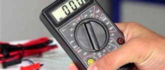
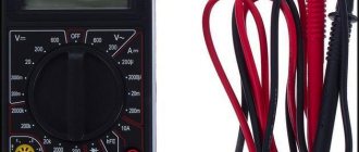
A digital multimeter consists of a display, a function selection switch (I just call it a knob), sockets where probes are inserted, and the probes themselves.
With cheap multimeters, when measuring any value, you need to select the range to be measured, therefore, you can often see numbers such as 2, 20, 200, and so on, which indicate the maximum measurement range.
Instructions for the multimeter
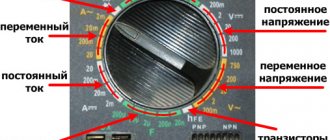
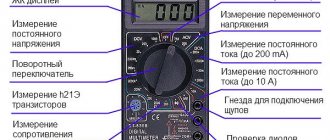
On the front part we see a switch with which we can select the functions we need. Let's look at the symbols that are on the multimeter. I marked each function with a number for ease of perception.
1) Resistance Ω. This icon tells us that we are going to measure the resistance of some conductor or resistor.
2) Constant voltage =V. By setting the switch to this icon, we can measure DC voltage.
3) AC voltage ~V. With this function we can measure the value of AC voltage.
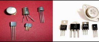
4) Measurement of the gain of hFe transistors. I don’t use it, because I have a transistormeter special for this purpose. You can read more about the gain in this article.
5) Capacitor capacity F. Everything is obvious. Capacitance can be measured.
6) DC voltage current measurement =A. We can measure the current strength of direct voltage.
7) Measurement of AC voltage current ~A. With this function we can measure the current of AC voltage. For example, this function is useful when we need to find out how much current flows in the circuit when we connect an incandescent lamp or some other load to a 220 Volt network.
8) Diode continuity test and continuity test of conductors. Shows resistance if you measure the integrity of conductors. When checking diodes, it shows the voltage drop across the PN junction. The beauty of this function is that if a resistance of less than 100 Ohms is displayed (it is different for different models), a screaming signal is heard from the multimeter. A very convenient function for checking diodes, as well as the integrity of wires and fuses. If you buy a multimeter, be sure to buy one with a diode tester, otherwise such a multimeter will suddenly lose its functionality.
Checking work
Dial icon
Make sure you have connected the probes correctly.
We check the reliability of the connection. To do this, switch the multimeter to diode continuity mode. In this mode, the voltage drop across the probes is measured.
If you close the probes, the device will show zero.
Probe short circuit (zero)
The unit denotes infinity, that is, a break in the circuit or the limit of measurement.
Measurement limit (or break)
Rules for using a multimeter
First you need to familiarize yourself with the technical data sheet of the device, study its capabilities and measurement limits.
When taking measurements, do not touch the metal base of the probes. If you check the details, this may affect the readings, they will be false. And when testing high voltages, if you touch the metal base of the probes, you can get an electric shock.
How to check voltage with a multimeter
DC voltage measurement
As you know, there are two types of voltage: alternating and constant. Any multimeter has at its disposal the functions of measuring direct and alternating voltage. To measure the voltage, we must touch the leads of the power supply with the probes. As you can see, it is advisable to connect the minus of the power supply to the minus of the multimeter (COM-black probe), and the plus to the red probe of the multimeter.
measuring DC voltage using a multimeter
In order to measure DC voltage, we must set the switch to the “=V” icon or similar. Let's measure the voltage on the battery, since the battery produces a constant voltage.
To do this, set the switch on the multimeter to measure DC voltage. For a more accurate measurement, I set the range to 20 Volts. We touch the battery with the probes and look at the value on the display. 1.28 Volts, which is considered normal for a nickel-manganese battery.
In order to measure the voltage on any chemical current source, we simply set the range we need, then make sure that the probes are in their places (black on COM, red on V) and then touch the terminals of the battery, accumulator or any other current source.
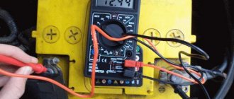
Here, for example, I measure the voltage on a car battery.
You can also measure the voltage from a laboratory power supply that produces direct current. Let's demonstrate what it all looks like. I set the voltage on the power supply to 10 Volts and measure this voltage with a multimeter.
measuring DC voltage from the power supply
But what happens if we reverse the polarity? That is, we connect the red probe of the multimeter to the minus, and the black probe to the plus? The digital multimeter in this case will simply show a minus sign.
In modern multimeters, this icon is already combined with the AC icon and looks like this:
combined icon of direct and alternating voltage Here, using the function key, we ourselves choose what current we will measure: direct or alternating. Direct current is designated DC - direct current, which literally translated from English is “direct current”.
function switching key
In the example below, I measured the voltage on a lithium-ion battery.
AC voltage measurement
To check the alternating voltage, we must set the functionality selection switch to the “~V” icon. I think you are aware that the voltage in the outlets in your home is variable. Let's measure its value. As you can see, the multimeter showed 215 Volts, although it should be something around 220 Volts. This voltage is still within the operating range, so everything is fine.
For a multimeter with automatic range measurement, we need to select the AC icon on the display of your device using the FUNC key. AC - alternating current, which literally translated into English is alternating current.
This is how the voltage in an outlet is measured. 228 Volts, which is also quite normal.
Design and principle of operation of a multimeter
The design of the devices differs into 2 types
- Stationary;
- Wearable.
The cheapest pocket models are with a dial indicator. This is a small ammeter with a built-in set of high-precision resistors of different values. The ohmmeter has a built-in power supply.
Stationary models are powered from a direct or alternating current network. These are high-precision instruments for testing circuits and electrical components. They are used at stands, in laboratories and large service centers.
Additionally, they can be connected to a computer network via the RS232 bus. On their basis, huge measuring systems are created that record and process information.
Device structure:
- electronic screen;
- name of designation;
- value switch;
- power button or special control position;
- probe sockets;
- special connectors for testing transistors (not available on all models);
- buzzer or dial indicator LED;
- power supply.
The main element is the designation scale (name). Inaccurate setting of parameters can lead to burning of the radio component, fuse or the device itself.
The operating principle is based on the use of a dual integration analog-to-digital converter. This is implemented using a controller. The converter compares the received signal with the reference signal and displays the value on the screen.
Analog
Without going into too much scientific definition, an analog device differs from a digital device by the presence of dial gauges. Pointer models are valued by amateurs and professionals for the smooth movement of the pointer. The downside is that the measurements are not very accurate.
Digital
A digital instrument differs from an analog instrument in clear and accurate readings, which are displayed in numbers on the dial. This is why he is valued.
How to measure current with a multimeter
Measuring current in a DC circuit
In order to measure the current in a circuit, we must connect a multimeter to the open circuit.
On simple digital multimeters, you need to transfer the red probe to socket A or mA, which means Amperes. You haven't forgotten that current is measured in Amperes, right?
In order to measure the current in a DC circuit , we must set the switch to “=A”. So, in our case, we will supply voltage from the power supply to the computer fan.
We assemble this whole thing according to our scheme, but instead of an incandescent lamp we will have this fan.
Since my power supply already has a built-in ammeter, I can compare the readings on the multimeter and on the power supply. As you can see, they are completely identical. The current value in the circuit is 0.18 Amperes.
On a cooler multimeter we display one of these icons.
If you don’t know at all what approximate current strength should be in your circuit, then always set the switch to the highest range. In this case, at A. Let's check the current consumed by a 12-volt incandescent lamp. To do this, set the voltage on the power supply to 12 Volts and place a multimeter in the open circuit. That is, we do everything as it is according to this scheme.
As you can see, the current in the circuit is 0.707 Amperes. This means that an incandescent lamp at 12 Volts consumes a current of 0.707 Amps.
measuring DC current using a multimeter
Measuring current in an AC circuit
In order to measure the current in an AC circuit, we need to set the switch to the “~A” icon. In cool multimeters we put the function switch on one of these icons
and then we select using the “AC” function key, which indicates that we are going to measure the current in an alternating current circuit.
In order to demonstrate this, I will need a laboratory autotransformer (LATR).
laboratory autotransformer
This autotransformer allows you to obtain an alternating voltage of a lower value than in a 220 Volt home network. I set the voltage at the LATR output to 12 Volts. Don't forget that these 12 volts are alternating voltage. I connect the whole thing using the same scheme. By the way, the incandescent lamp here is more powerful, therefore, it will consume more current.
What does tension tell you?
For a car battery, the voltage will immediately indicate what to do with the battery. To properly check a car battery, we take two measurements. We set the tester selector to 20 V.
With the engine running
The first measurement is with the engine running. There should be from 13.5 to 14 V at the terminals. If it is more than 14.2 V, the battery is low and the generator produces increased voltage to recharge the battery. This can happen, for example, in the cold - self-discharge of batteries at low temperatures has not been canceled. But if this happens in the summer, and on an old battery, you should at least have the battery serviced by an electrician. If, when the engine is running, the voltage at the battery terminals is less than 13.4 V, turn off all consumers - headlights, radio, heating. And we measure again. We get the same result - a reason to go to the service, the generator is faulty.
With the engine not running
When the engine is not running, the voltage on a working battery should be from 12.5 to 13 V. A drop in voltage indicates a drop in the charge level. If your charge level is constantly low, and this can happen during short trips and an old battery, you should at least occasionally charge the battery with a special device. The charge level of a 55 Ah car battery can be approximately estimated from the table.
| Voltage, V | 12,9 | 12,5 | 12,1 | ||
| Charge level, % | 90 | 50 | 10 | ||
When the voltage is 13 V, the battery is fully charged. If the voltage is less than 12.1 V, the battery is discharged and the car is unlikely to start. A voltage drop below 12 V is a deep discharge that is fatal to the battery. 3-4 such discharges are guaranteed to kill the plates. Watch the video of the channel I Want to Know Everything.
How to test a capacitor with a multimeter
In order to check the integrity of the capacitor with a multimeter, its capacitance must be 1 µF or higher. This trick only works with analog multimeters, as well as with digital range selecting multimeters, such as these.
As you know, capacitors are polar and non-polar. Read more here. Polar capacitors have a large capacity, so they are easier to check for functionality. How to do this? Let's take a look at the example below.
We have an electrolytic capacitor.
We set the multimeter to the continuity mode and touch the leads of the capacitor with the probes. We carefully watch the numbers on the scoreboard. They should increase as the capacitor charges.
As soon as I touched the leads, the multimeter immediately showed this value
in half a second
and then the value went out of range, and the multimeter showed one.
So what can we say? At the very initial moment of time, a completely discharged capacitor behaves like a conductor. As it is charged with current from the multimeter, its resistance increases until it becomes very high. Once the capacitor is charged, it means it is working. Everything is logical.
Capacitors of smaller capacity and non-polar capacitors can be tested using a tester only for a short circuit between its plates. Therefore, a different iron method is used here. Just measure the capacitance of the capacitor). Here I measured the capacitance of the capacitor, on which 47 uF was written. The multimeter showed 48 uF. Either the error of the capacitor or the multimeter. Since Mastech multimeters are considered to be quite good, we will attribute it to the capacitor error).
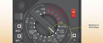
How to measure resistance with a multimeter
So, we have everyone's favorite digital multimeter
In order to measure resistance, we need to turn the function selection switch to “resistance measurement”. This is our entire top row in green with the letter Ω. The letter “K” tells us that we are going to measure kilo-ohms, and the letter “M” means that we are going to measure mega-ohms. The measurement limit is shown before the letter. If a 1 lights up on the multimeter display when measuring resistance, then we switch to a higher limit.
How to test a fixed resistor
So, we have this resistor.
We see the inscription “82R” on it. It means that its resistance should be 82 Ohms. You can read more about resistor markings in this article. To do this, apply one probe to one end of the resistor, and the other probe to the other end.
As you can see, the multimeter almost accurately showed the resistance value of this resistor.
How to test a variable resistor
Let's measure the resistance of the variable resistor. As you know, with a variable resistor we can change the resistance manually. The same applies to tuning resistors - this is one of the types of variable resistors.
This is his view from below. Here we see the inscription 47 KM. This means its resistance should be 47 KiloOhms between the two extreme contacts.
Using the handle, we can turn it clockwise or counterclockwise, thereby changing the resistance between the middle contact and the two outer contacts
Here is its schematic designation:
We place the probes at the extreme contacts. We measure the total resistance of the variable resistor.
Hmmm... A little different resistance. Our variable resistor is too old, which may be why its resistance does not match what is written on it. In order to check whether it is working, turn the variable resistor knob all the way counterclockwise and measure the resistance between the left and middle contacts. It should be close to zero.
Turn the handle clockwise, but not all the way. We measure the resistance between the middle and left contacts again.
We measure the resistance between the middle and right contacts.
The total should be the result of the resistance of the two extreme contacts. 12.2+27.6=39.8 Almost everything is correct. Therefore, our variable resistor is working properly.
Rules for measuring resistance
- Press the probes with some force onto the resistor terminals. In this way, you will eliminate the appearance of contact resistance, which, when pressed lightly, will add up to the measured resistance.
- Do not measure resistance under voltage! This could damage the multimeter or cause you an electric shock!
- When measuring the resistance of a resistor on a printed circuit board, double-check that the board is de-energized. Then unsolder one end of the resistor and then measure its resistance.
- Do not touch the resistor leads when measuring its resistance! The average human body has a resistance of about 1 KiloOhm and depends on many factors. Therefore, by touching the resistor terminals when measuring resistance, you introduce an error into the measurements.
- If you want to measure the resistor's resistance as accurately as possible, clean its terminals either with a knife or with the mildest sandpaper. In this case, you will remove the oxide layer, which in some cases introduces a noticeable error in the resistance measurement.
Measuring resistance
To measure resistance, set the switch to resistance mode (Ω) and select the desired range. One of the probes is applied to one input of the resistor, the other to the other. The display will show the resistance value. By switching the range you can get the desired dimension of the resistance value.
If “zero” is displayed on the display, then the range should be reduced, and if “1” then increased.
How to make calls with a multimeter
All modern digital multimeters have a dialing function.
Continuity testing is the same “resistance measurement” function, but only in this case the multimeter makes a squeak if the resistance is less than 100 Ohms. Why is this function needed? In order to check the integrity of wires, fuses, incandescent lamps, printed conductors, and so on. A very convenient and indispensable function in any multimeter. Most often, the continuity icon is combined with a diode continuity indicator. It all looks something like this:
diode continuity
For example, I want to ring a light bulb and find out if it is intact? To do this, I put the switch on the corresponding icon and touch the lamp with the probes. The multimeter emits a heart-rending “piiiiip” sound, and the display of the multimeter shows the filament resistance reading. This means that the light bulb is alive, since the tungsten filament is not broken.
continuity test with a multimeter
Connect the wire to determine the temperature
The temperature wire plug has pins marked with plus and minus symbols. The connector on the multimeter body is also equipped with polarity markings. We insert the plug into the connector like this: plus to plus, minus to minus.
The editors urge you to read the instructions and follow safety precautions before using any devices.
Take care of yourself.
Proven Multimeters
With my many years of experience in the field of electronics, I have changed many multimeters. I would like to focus on two brands that made me very happy and still make me happy in my difficult task.
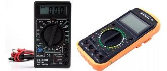
Multimeters DT9205
Large display, convenient functionality, automatic shutdown function, inexpensive cost. If you look through the pages of my website, you will see that I used exactly these models of multimeters in my practice. They are very comfortable and durable. Yes, they are large, but it's worth it. This multimeter fits very comfortably in your hand.
Here is the link to Aliexpress. Try to take exactly the same one as in the photo above. Its cost is in the range of 700-800 rubles.