The measurement rules state that a voltmeter is connected to the required section of the electrical circuit in parallel, and an ammeter in series. Therefore, in order to measure the current strength, it is necessary to artificially create an open circuit and connect a measuring device to it. To simplify and speed up measurements, current clamps are used, which work using a fundamentally different method - their device allows you to measure the intensity of the electromagnetic field that always arises around the conductor.
Current clamp device
Initially, an electrical clamp was a transformer to which a measuring device, an ammeter, was connected.
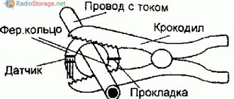
The clamps, which are the visible part of the device, are also the primary winding of the transformer. If a conductor is placed inside it through which an electric current flows, then thanks to the electromagnetic field it is induced onto the winding of the transformer. Next, the current passes to the secondary winding, from which readings are taken with an ammeter.
The first models of clamps were created as an addition to measuring instruments, simply allowing more convenient contact with the measured section of the chain.
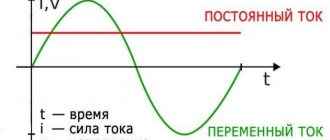
The ammeter readings obtained with their help had to be additionally recalculated, taking into account the transformation ratio that was indicated on the device. Also, the principle of operation itself made it possible to measure only alternating current values, since the transformer does not work with constant current - in order to measure it, it was necessary to use other devices.
Modern instruments can be used both for alternating current and as a clamp for accurate measurement of direct current, but in the latter case, such devices do not use an ammeter, but a Hall sensor, which directly senses the presence and strength of the electromagnetic field.
Such models are somewhat more expensive, but are distinguished by higher quality and accuracy of work.
Also, using a clamp meter paired with a digital multimeter eliminates the need for the operator to calculate the measured current value, since the calculator is already built into the device circuit.
Three-phase transformer with customizable winding connection
Winding 1 connection (ABC terminals)
Winding connection for winding 1. The options are Y , Yn , Yg (default), Delta (D1) and Delta (D3).
Winding connection 2 (abc terminals)
Winding connection for winding 2. The options are Y , Yn , Yg (default), Delta (D1) and Delta (D3).
Type
Select Three single-phase transformers from (default) to realize a three-phase transformer using three models of single-phase transformers. You can use this type of core to represent very large power transformers used in electrical networks (hundreds of MW).
Select Three-limb core (rod type) to realize the triple-leg core of three-phase transformer. In most applications, three-phase transformers use a three-leaf core (transformer core). This type of core gives accurate results during asymmetric failure for both linear and nonlinear models (including saturation). During asymmetric voltage, the zero-sequence flux of the core transformer returns outside the core through the air gap, structural steel and tank. Thus, the natural zero-sequence inductance L0 (without delta winding) of such a core transformer is usually very low (typically 0.5 pu to 100 pu). This low value of L0 affects imbalances in voltages, currents and magnetic fluxes during linear and busy work.
Select five-point core (cladding) to realize the five-point core three-phase transformer core.
In rare cases, very large transformers are made with a five-lobe core (three phase and two external). This basic configuration, also known as the shell type, is chosen mainly to reduce the height of the transformer and make transportation easier. Under unbalanced voltage conditions, unlike a three-leg transformer, the zero-sequence flux of a five-leg transformer remains inside the steel core and returns through the two outer limbs. The natural zero sequence inductance (without delta) is very high (L0> 100 pu). Except for small current imbalances due to core asymmetry, the behavior of a five-terminal shell-type transformer is similar to that of a three-phase transformer consisting of three single-phase units. Simulate saturation
If selected, implements a saturable three-phase transformer. Cleared by default.
If you want to model a transformer in a vector mode Powergui Block, you must clear this parameter.
Simulate Hysteresis
Select to simulate saturation characteristics, including hysteresis, instead of a single-valued saturation curve. This option appears only if Simulate has the Saturation option selected . The default is Clear.
If you want to model a transformer in a vector mode Powergui Block, you must clear this parameter.
Hysteresis Matrix File
This option appears only if Simulate has the Hysteresis option selected .
Specify a .mat file containing data to use in hysteresis. model. When you open the Hysteresis Design Tool of a Powergui block, the default hysteresis loop and parameters saved in the hysteresis .mat file are displayed. Use the Load of the Hysteresis Design tool. to load another .mat file. Use the Save on the Hysteresis Design tool to save your model as a new .mat file.
Define Starting Threads
If selected, starting threads are defined by Starting Threads on the Options . Specify The initial flows option is only visible if Simulate has the Saturation option selected . Cleared by default.
When the Specify Initial Flows option is not selected during simulators, Simscape™ Electrical™ Specialized Power Systems software automatically calculates the initial flows to run the steady state simulation. The calculated values are stored in Initial. Changes the parameter and overwrites all previous values.
Measurements
Select Winding Voltages to measure the voltage across the winding terminals.
Select Winding Currents to measure the current flowing. through the windings.
Select Fluxes and field currents (Im + IRm) to measure the flux linkage in volt-seconds (V.s) and the total field current, including iron losses, modeled by Rm.
Select Fluxes and Magnetizing Currents (Im) to measure flux linkage in volt-seconds (V.s) and magnetizing current in amperes (A), rather than including steel losses modeled by Rm.
Select All Measurements (V, I, Flux) to measure winding voltages, currents, magnetizing currents and flux.
Default: No.
Place a multimeter block in your model to display selected measurements during the simulation. In the Available Measurements Multimeter Block list box, measurements are indicated by a label followed by the block name.
If the Winding 1 connection (ABC terminals) is set to Y, Yn, or Yg, the labels are as follows.
8
| Measurement | Label | |
| Winding 1 voltage | Uan_w1: 0001 9_w1: 7 1 currents | Ian_w1: or Iag_w1: |
| Fluxes | Flux_Are0008 | |
| Excitation currents | Iexc_A: |
The same labels apply to winding 2, except that 1 is replaced by 2 in the labels.
If the Winding 1 connection (ABC terminals) is set to Delta (D1) or Delta (D3), the labels are as follows.
| Measurement | Label |
| Winding 1 voltage | Uab_w1: |
| Winding currents 1 | Iab_w1: |
| Streaming connections | Flux_A: 900_70008 Flux_A: 900_7 |
| Excitation currents | Iexc_A: |
.
Capabilities of clamp meters
If clamps were initially created as an addition to professional measuring instruments, then further industry opportunities for miniaturization and simplification of devices made this device relatively inexpensive and accessible to ordinary users for domestic use.
At the same time, the scope of its use is constantly growing and only standard tasks that can be performed with its help include the following items:
- Measuring the current strength in a single conductor, which is not only not disconnected from the circuit, but is also energized.
- Determination of the actual power of any electrical appliance at different times and depending on the load.
- Determination of the actual load on the entire electrical network of a house or apartment “in real time”.
- Checking the electrical network for unauthorized connections.
- Checking for current leakage on the body of the electrical appliance.
Method for measuring power with two wattmeters - with a star and delta connection
The two-wattmeter method can be used to measure power in a three-phase, three-wire wye or delta connection, balanced or unbalanced load.
In the two wattmeter method, the current coils of the wattmeter are connected to any two lines, say R and Y, and the potential coil of each wattmeter is connected on one line, the third line, that is, B, as shown below in figure (A):
The total instantaneous power consumed by the three loads Z 1, Z 2 and Z 3 is equal to the sum of the powers measured by the two wattmeters, W 1 and W 2.
Included:
Power measurement using the two-wattmeter method with a star connection
Given the above figure (A), in which two wattmeters W 1 and W 2 are connected, the instantaneous current through the wattmeter's current coil, W 1 , is given by the equation shown below:
The instantaneous potential difference across the wattmeter coil, W 1, is defined as:
Instantaneous power measured by wattmeter, W 1 —
The instantaneous current through the current coil of the wattmeter, W 2, is determined by the equation:
The instantaneous potential difference across the wattmeter coil, W 2, is defined as:
Instantaneous power measured by wattmeter, W 2:
Thus, the total power measured by two wattmeters W 1 and W 2 will be obtained by adding equations (1) and (2).
Where, P is the total power consumed by the three loads at any given time.
Power measurement using the two-wattmeter method using a delta connection
Considering the delta connection diagram shown in the figure below:
The instantaneous current through the wattmeter coil, W 1, is determined by the equation:
The instantaneous power measured by a wattmeter, W 1, will be:
Therefore, the instantaneous power measured by the wattmeter, W 1, will be represented as:
The instantaneous current through the current coil of the wattmeter, W 2, is defined as:
Instantaneous potential difference across the wattmeter potential coil, W 2:
Therefore, the instantaneous power measured by a wattmeter, W 2, will be:
Therefore, to obtain the total power measured by two wattmeters, two equations must be performed, i.e. equation (3) and (4) need to be added.
Where P is the total power consumed by the three loads at any given time.
The power measured by a two-watt meter at any given time represents the instantaneous power consumed by three loads connected to three phases. In fact, this power is the average power consumed by the load as the wattmeter reads the average power due to the inertia of their moving system.
.
Advantages and disadvantages
Current clamps have become widespread due to a number of advantages that determine the choice in their favor, if necessary, have a corresponding device “on hand”:
- The maximum possible simplicity, device size and measurement accuracy.
- Possibility of use for measurements in high-voltage circuits and microcurrents.
- The operating principle of pliers allows you to create devices of various designs and functionality.
- Easy integration with other electrical measuring devices. For example, current clamps combined with a multimeter have proven to be very effective - the limits of possibilities for household use for such devices are very difficult to imagine, since they can be equipped with a temperature sensor and other “goodies” that expand the functionality.
The device is extremely easy to use; its development, even on an intuitive level, is accessible to anyone who is even more or less familiar with the basics of electrical engineering.
When using electrical clamps, one must take into account some of the inherent disadvantages of such devices:
- Since the device reacts to an electromagnetic field, there is some dependence on the position of the wire inside the primary winding (ring) and its position - it is advisable to place the clamps perpendicular to the conductor being measured.
- A sensitive device can be very susceptible to interference currents that can occur when there are a large number of conductors close to what is being measured.
- The simplicity of the device design opens up wide opportunities for the production of low-quality clones of devices from reputable manufacturers. Such copies are not equipped with proper protection schemes and the accuracy of their readings leaves much to be desired.
Types of current clamps
Depending on the circuit used and even the appearance of the device itself, electrical clamps are divided into several types:
- Switches. An analog type device, the active part of which is a single-turn AC transformer, and the measuring device is connected to its secondary winding. These are one of the first models of current clamp meters - they are distinguished by their low cost and clear display of measurement results in the case of variable current. A common disadvantage of such devices is their high sensitivity to mechanical vibrations - if the device is not placed on a hard surface, the measurement result may be displayed incorrectly. Also, to use such devices you need a certain skill - you often have to manually convert the ammeter readings into real values in accordance with the transformation ratio. This device is also designed for a certain frequency of electric current.
- Digital. The display of readings on such a device is determined by a microcontroller, which automatically performs all the necessary calculations and (depending on the model) can be configured to directly display current or power.
- Multimeter. A universal all-in-one device - the measuring clamps are built directly into the body of the device, which makes it easy to use. The number of functions and measurement methods is determined by the model of the multimeter, so the correct name for the device would not be an electric clamp with a multimeter, but vice versa. Often such devices work with a Hall sensor, so they can be used as DC current clamps.
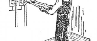
- High voltage. The main application is electrical circuits with standard frequency current and voltage exceeding 1 kV. Such devices have increased insulation resistance and can additionally be mounted on a dielectric rod so that the operator does not come close to the conductor from which measurements are taken. This is a specialized professional device that is designed for only one single function - measuring alternating current. If it is necessary to measure the direct current, other devices and methods are used.
Three-phase transformer with customizable winding connection
Winding 1 connection (ABC terminals)
Winding connection for winding 1. The options are Y , Yn , Yg (default), Delta (D1) and Delta (D11).
Winding connection 2 (terminals abc-2)
Winding connection for winding 2. The options are Y, Yn, Yg (default), Delta (D1), and Delta (D11).
Winding connection 3 (terminals abc-3)
Winding connection for winding 3. The options are Y, Yn, Yg (default), Delta (D1), and Delta (D11).
Type
Select Three single-phase transformers from (default) to realize a three-phase transformer using three models of single-phase transformers. You can use this type of core to represent very large power transformers used in electrical networks (hundreds of MW).
Select Three-limb core (core type) to realize the triple-leg core of a three-phase transformer. In most applications, three-phase transformers use a three-leaf core (core transformer). This core type gives accurate results during asymmetric failure for both linear and nonlinear models (including saturation). During asymmetric voltage, the core transformer's zero-sequence flux returns outside the core through the air gap, structural steel, and tank. Thus, the natural zero-sequence inductance L0 (without delta winding) of such a core transformer is usually very low (typically 0.5 p.u. 100 p.u.). This low L0 value affects voltage, current and flux imbalances during linear and saturated operation.
Select Penta-lobe core (cladding type) to realize the penta-lobe core of a three-phase transformer. In rare cases, very large transformers are manufactured with Penta-lobe core (three phase and two outer).
This basic configuration, also known as the shell type, is chosen mainly to reduce the height of the transformer and make transportation easier. Under unbalanced voltage conditions, unlike a three-leg transformer, the zero-sequence flux of a five-leg transformer remains inside the steel core and returns through the two outer limbs. The natural zero-sequence inductance (without delta) is very high (L0 > 100 pu). Except for small current imbalances due to core asymmetry, the behavior of a five-terminal shell-type transformer is similar to that of a three-phase transformer consisting of three single-phase units. Simulate saturation
If selected, implements a saturable three-phase transformer. See also Saturation Characteristics Option on the Options tab.
Cleared by default. Simulate Hysteresis
Select to simulate saturation characteristics, including hysteresis, instead of a single-valued saturation curve. This option appears only if Simulate is the saturation option selected .
Cleared by default. Hysteresis Matrix File
This option appears only if Simulate has the Hysteresis option selected .
Specify a .mat file containing the data to be used for the hysteresis model. When you open Hysteresis Design Tool Powergui, the default hysteresis loop and parameters are saved in hysteresis.mat. Use the Load in the Hysteresis Design tool to load another .mat file. Use the Save on the Hysteresis Design Tool to save the model as a new .mat file.
Specify Initial Threads
If selected, initial threads are determined by the Initial Threads option on the Options tab. This option appears only if Simulate has the Saturation option selected . The default is Clear.
When the Specify Initial Flows option is not selected during simulators, Simscape™ Electrical™ Specialized Power Systems software automatically calculates the initial flows to run the steady state simulation. The calculated values are stored in Initial. Changes the parameter and overwrites all previous values.
Measurements
Select Winding Voltages to measure the voltage across the winding terminals of a three-phase transformer block.
Select Winding Currents to measure the current flowing. through the windings of a three-phase transformer block.
Select Fluxes and excitation currents (Imag + IRm) from to Measure the flux linkage in volt-seconds (V.s) and the total excitation current, including steel losses, modeled by Rm.
Select Fluxes and Magnetizing Currents (Imag) to measure flux linkage in volt-seconds (V.s) and magnetizing current in amperes (A), rather than including steel losses modeled by Rm.
Select All Measurements (V, I, Flux) to measure winding voltages, currents, magnetizing currents and flux.
Default: No.
Place a multimeter block in your model to display selected measurements during the simulation. In the Available Multimeter Measurements list box of a block, measurements are indicated by a label followed by the block name.
If the Winding 1 connection (ABC terminals) is set to Y, Yn or Yg, the same labels follow.
| Measurement | Label | |
| Winding 1 voltage | Uan_w10007 1 currents | Ian_w1: or Iag_w1: |
| Flux-lever gears |
Procedure for working with current clamps
Methods for measuring using current clamps are generally no different when using household multimeters (up to 1000 Volts) or professional (over 1000 Volts) devices.
A mite tester designed for home use will have many more functions, but a specialized device in a domestic setting will most often have nothing to measure.
Depending on the purpose of the measurements, the entire process using clamps combined with a multimeter will proceed as follows:
- Among the wires, the one from which readings need to be taken stands out. If you grab several conductors with pliers at once, the measurement result will be incorrect.
- The tester sets the required mode and range. If alternating current is measured, then it will be the letters AC, and when the device supports direct current measurement, then it will be DC. In this case, on the scale you need to select a value slightly larger than the one you plan to measure. If the estimated current strength is unknown, then measurements should be started from the largest scale.
- The pliers open and the required conductors are placed inside. For the most accurate measurement, it is advisable to place the wire in the center of the circuit, perpendicular to the body of the device.
- The measurement will take place automatically and the results will be shown on the display.
How to use
The principle of using this device is quite simple; you need to determine the place where you will take measurements. If this is a hard-to-reach cabinet with wires, then the device should be equipped with a locking button. Working with current clamps involves selecting a measurement mode by installing the sensor in the desired position, after which the clamps are connected to the conductor being measured. If it is not possible to measure the network load and the display shows a single value, then it is necessary to set the sensor to a higher value. Current clamps are convenient to use not only for professional electricians, but also for ordinary users.
All clamps assume the ability to measure direct and alternating current and resistance.
Useful nuances of taking measurements
Knowledge of some physical laws and structural features of the device will allow you to expand the scope of its application.
If the current in the conductor is very small and the tester cannot accurately determine it, then you can “help” the device by winding the conductor around one of the clamp halves. In this case, the display will display the sum of the currents and to find out the exact value you need to divide the result by the number of turns.
If the current is greater than what the tester can show, then the display will show one. In this case, you need to set a larger measurement range and repeat the measurements.
It will be possible to detect leakage current without searching for its presence on the grounding wire (connected to the device body). To do this, you can take advantage of the tester’s ability to show the sum of the currents of several conductors placed in an electrical clamp. If you grab the phase and zero with pincers at once, then zero should appear on the display, since the induced electromagnetic fields are mutually compensated (they must be equal in strength and different in direction). If there is a leak, the value on the display will be different from zero - if this is the case, then you need to look for the location of the insulation breakdown on the housing.
If there is a “Hold” button on the body of the measuring device, this will help measure current in hard-to-reach places, for example, if you can reach there with the tester, but the display will not be visible. In this case, you need to wrap the current clamp around the wire, press this button, and the result will be recorded on the display - now you can view it in a convenient place.