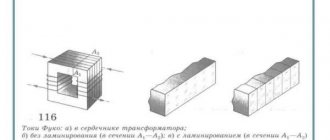
Transformer dimensions
Table 5.11
| Dimensions | Group | Power range, kVA | Voltage class, kV |
| I | 1 | Up to 20 | Up to 35 inclusive |
| 2 | 25-100 | ||
| II | 3 | 160-250 | |
| 4 | 400-630 | ||
| 5 | 1000 | ||
| III | 6 | 1600-2500 | |
| 7 | 4000-6300 | ||
| IV | 8 | 10 000-32 000 | |
| 9 | Over 32,000 | ||
| V | 10 | Up to 16,000 | 110 and 150 |
| 11 | 25 000-32 000 | ||
| VI | 12 | 40 000-63 000 | 110i150 |
| 13 | Up to 63,000 | 220 and 330 | |
| VII | 14 | 80 000-200 000 | 110i150 |
| 15 | 80 000-200 000 | 220 and 330 | |
| VIII | 16 | Over 200,000 | Up to 330 |
| inclusive | |||
| 17 | Regardless of power | Over 330 | |
| 18 | For power transmission | Regardless | |
| direct current | voltage | ||
| regardless of power |
Note: Transformers having a power or voltage not corresponding to the standard scale are assigned to the size and group of the nearest standard power or voltage.
The concept of rated power of a transformer
The rated power of a transformer is the total power for which the device is designed by its manufacturer. That is, the voltage that the transformer can withstand without interruption throughout its entire service life.
Factories provide a service guarantee of 20 to 25 years.
This indicator is always related to the operating temperature: how much heating of the windings is allowed and under what conditions the unit is cooled. For different powers of the transformer windings, the rated one is considered to be the highest. Basically, transformers are equipped with oil cooling, which directly depends on the ambient temperature.
Since weather conditions are constantly changing, the greatest heating of the windings at maximum air heat is considered the upper limit of the average temperature resistance that is possible to maintain safety.
For devices with a different type of cooling, the manufacturer’s passport specifies the nominal temperature conditions.
In addition to the rated power, there is a typical power of the transformer, which is calculated as the sum of the load values on all windings, divided by two. And the maximum load on the windings is calculated as the product of the maximum current value and the maximum permitted voltage of a given part of the circuit.
Three-phase two-winding transformers 35 kV
Table 5.12
| Type | Snom, MBA | Regulation limits | Catalog data | Calculation data | |||||||
| Unom of windings, kV | IR, % | Pk, kW | Рх, kW | Iх, % | RT, Ohm | Xt, Ohm | Qx, kvar | ||||
| VN | NN | ||||||||||
| TM- 100/35 | 0,1 | +2×1,5% | 35 | 0,4 | 6,5 | 1,9 | 0,5 | 2,6 | 241 | 796 | 2,6 |
| TM- 160/35 | 0,16 | ±2×1,5% | 35 | 0,4; 0,69 | 6,5 | 2,6; 3,1 | 0,7 | 2,4 | 127; 148 | 498 | 3,8 |
| TM- 250/35 | 0,25 | +2×1,5% | 35 | 0,4; 0,69 | 6,5 | 3,7; 4,2 | 1,0 | 2,3 | 72; 82 | 318 | 5,7 |
| TMN (TM)-400/35 | 0,4 | ±6×1,5% | 35 | 0,4; 0,69 | 6,5 | 7,6; 8,5 | 1,9 | 2,0 | 23,5; 26,2 | 126 | 12,6 |
| TMN (TM)-630/35 | 0,63 | ±6×1,5% | 35 | 0,4; 0,69; 6,3; 11 | 6,5 | 11,6; 12,2 | 2,7 | 1,5 | 14,9; 14,2 | 79,6 | 15 |
| TMN (TM)-1000/35 | 1 | ±6×1,5% | 35 | 0.4; 0.69; 6.3; AND | 65 | 16,5; 18 | 36 | 1,4 | 7,9; 8,6 | 49,8 | 22,1 |
| TMN (TM)-1600/35 | 1,6 | ±6×1,5% | 35 | 6,3; 11 | 6,5 | 23,5; 26 | 5,1 | 1,1 | 11,2; 12,4 | 49,2 | 17,6 |
| TMN (TM)-2500/35 | 2,5 | ±6×1,5% | 35 | 6,3; 11 | 6,5 | 23,5; 26 | 5,1 | 1,1 | 4,6; 5,1 | 31,9 | 27,5 |
| TMN (TM)-4000/35 | 4,0 | ±6×1,5% | 35 | 6,3; 11 | 7,5 | 33,5 | 6,7 | 1,0 | 2,6 | 23 | 40 |
| TMN (TM)-6300/35 | 6,3 | ±6×1,5% | 35 | 6,3; 11 | 7,5 | 46,5 | 9,2 | 0,9 | 1,4 | 14,6 | 56,7 |
| TD-10000/35 | 10 | ±2×2,5 % | 38,5 | 6,3; 10,5 | 7,5 | 65 | 14,5 | 0,8 | 0,96 | 11,1 | 80 |
| TMN-10000/35 | 10 | ±9×1,3% | 36,75 | 6,3; 10,5 | 7,5 | 65 | 14,5 | 0,8 | 0,88 | 10,1 | 80 |
| TDNS- 10000/35 | 10 | ±8×1,5% | 36,75 | 6,3; 10,5 | 8,0 | 60 | 12,5 | 0,6 | 0,81 | 10,8 | 60 |
| TD- 16000/35 | 16 | ±2×2,5 % | 38,5 | 6,3; 10,5 | 8,0 | 90 | 21 | 0,6 | 0,52 | 7,4 | 96 |
| TDNS- 16000/35 | 16 | ±8×1,5% | 36,75 | 6,3-6,3; 10,5-10,5 | 10 | 85 | 18 | 0,55 | 0,45 | 8,4 | 88 |
| TRDNS- 25000/35 | 25 | ±8×1,5% | 36,75 | 6,3-6,3; 10,5-10,1 | 9,5 | 115 | 25 | 0,5 | 0,25 | 5,1 | 125 |
| TRDNS- 32000/35 | 32 | ±8×1,5% | 36,75 | 6,3-6,3; 10,5-10,5 | 11,5 | 145 | 30 | 0,45 | 0,19 | 4,8 | 144 |
| TRDNS- 40000/35 | 40 | ±8×1,5% | 36,75 | 6,3-6,3; 10,5-10,5 | 11,5 | 170 | 36 | 0,4 | 0,14 | 3,9 | 160 |
| TRDNS-63000/35 | 63 | ±8×1,5% | 36,75 | 6,3-6,3; 10,5-10,5 | 11,5 | 250 | 50 | 0,3 | 0,1 | 2,5 | 220 |
Notes:
- Voltage regulation is carried out on the HV side by on-load tap-changer or tap-changer.
- Transformers of type TM, indicated in brackets, have PCB ±2×2.5% on the HV side.
Standard power scale for power transformers
On the territory of Russia, a single scale of standard capacities is used. It is divided into two steps: 1.35 and 1.6, each including a number of values presented in the table below.
| Step 1.35. In kVA | Step 1.6. In kVA |
| 100 | 100 |
| 135 | 160 |
| 180 | 250 |
| 240 | 400 |
| 320 | 630 |
| 420 | 1000 |
| 560 | 1600 |
Currently, factories produce transformer substations (TS), using power steps of 1.6. The 1.35 pitch scale is no longer used in production, but old installations produced in Soviet times were designed precisely according to this scale. At the same time, studies have identified older devices as more profitable because they can work at full capacity, unlike modern units.
When choosing different types of devices, it is taken into account that they should be as close as possible in terms of the highest load indicator in normal mode and the maximum voltage in emergency mode.
When choosing transformers for industrial production, it is important to take into account their number for rational distribution of electricity and their typical power at a certain rated load.
Three-phase two-winding transformers 110 kV
Table 5.13
| Type | Snom, MBA | Regulation limits | Catalog data | Calculation data | |||||||
| Unom of windings, kV | IR, % | Pk, kW | Рх, kW | Iх, % | RT, Ohm | Xt, Ohm | Qx, kvar | ||||
| VN | NN | ||||||||||
| TMN-2500/110 | 2,5 | + 10×1,5% -8×1,5% | 110 | 6,6; 11 | 10,5 | 22 | 5,5 | 1,5 | 42,6 | 508,2 | 37,5 |
| TMN-6300/110 | 6,3 | +9×1,78% | 115 | 6,6; 11 | 10,5 | 44 | 11,5 | 0,8 | 14,7 | 220,4 | 50,4 |
| TDN- 10000/110 | 10 | +9*1,78% | 115 | 6,6; 11 | 10,5 | 60 | 14 | 0,7 | 7,95 | 139 | 70 |
| TDN-16000/110 | 16 | +9×1,78% | 115 | 6,6; 11; 34,5 | 10,5 | 85 | 19 | 0,7 | 4,38 | 86,7 | 112 |
| 1TDN- 25000/110 (TRDNF-25000/110) | 25 | +9×1,78% | 115 | 6,3-6,3; 6,3-10,5; 10,5-10,5 | 10,5 | 120 | 27 | 0,7 | 2,54 | 55,9 | 175 |
| TDNZh-25000/110 | 25 | +9×1,78% | 115 | 27,5 | 10,5 | 120 | 30 | 0,7 | 2,5 | 53,5 | 175 |
| TD-40000/110 | 40 | +2×2,5 % | 121 | 3,15; 6,3; 10,5 | 10,5 | 160 | 50 | 0,65 | 1,46 | 48,4 | 260 |
| TRDN-40000/110 | 40 | ±9×1,78% | 115 | 6,3-6,3; 6,3-10,5; 10,5-10,5 | 10,5 | 172 | 36 | 0,65 | 1,4 | 34,7 | 260 |
| TRDTsN-63000/110 (TRDN) | 63 | +9×1,78% | 115 | 6,3-6,3; 6,3-10,5; 10,5-10,5 | 10,5 | 260 | 59 | 0,6 | 0,87 | 22 | 410 |
| TRDTSNK-63000/110 | 63 | +9×1,78% | 115 | 6,3-6,3; 6,3-10,5; 10,5-10,5 | 10,5 | 245 | 59 | 0,6 | 0,8 | 22 | 378 |
| TDC-80000/110 | 80 | +2×2,5 % | 121 | 6,3; 10,5; 13,8 | 10,5 | 310 | 70 | 0,6 | 0,71 | 19,2 | 480 |
| TRDTSN-80000/110 (TRDN, (TRDTsNK) | 80 | +9×1,78% | 115 | 6,3-6,3; 6,3-10,5; 10,5-10,5 | 10,5 | 310 | 70 | 0,6 | 0,6 | 17,4 | 480 |
| TDC- 125000/110 | 125 | +2×2,5 % | 121 | 10,5; 13,8 | 10,5 | 400 | 120 | 0,55 | 0,37 | 12,3 | 687,5 |
| TRDCN- 125000/110 | 125 | +9×1,78% | 115 | 10,5-10,5 | 10,5 | 400 | 100 | 0,55 | 0,4 | 11,1 | 687,5 |
| TDC-200000/110 | 200 | ±2×2,5 % | 121 | 13,8; 15,75; | 10,5 | 550 | 170 | 0,5 | 0,2 | 7,7 | 1000 |
| TDC-250000/110 | 250 | ±2×2,5 % | 121 | 15,75 | 10,5 | 640 | 200 | 0,5 | 0,15 | 6,1 | 1250 |
| TDC- 400000/110 | 400 | +2×2,5 % | 121 | 20 | 10,5 | 900 | 320 | 0,45 | 0,08 | 3,8 | 1800 |
Notes:
- Voltage regulation is carried out by an on-load tap-changer in the neutral, with the exception of transformers of the TMN-2500/110 type with an on-load tap-changer on the LV side and a TD with a tap-changer on the HV side.
- Transformers of the TRDN type can also be manufactured with a non-split LV winding of 38.5 kV, 25 MVA transformers - with 27.5 kV (for electrification of railways).
Three-phase three-winding transformers 110 kV
Table 5.14
| Type | Snom, MBA | Catalog data | Calculation data | |||||||||||||||
| Unom of windings, kV | IR, % | Pk, kW | Рх, kW | Iх, % | RT, Ohm | Xt, Ohm | Qx, kvar | |||||||||||
| VN | CH | NN | B-C | V-N | S-N | VN | CH | NN | Sun | VN | CH | |||||||
| TMTN -6300/110 | 6,3 | 115 | 38,5 | 6,6; 11 | 10,5 | 17 | 6 | 58 | 14 | 1,2 | 9,7 | 9,7 | 9,7 | 225,7 | 0 | 131, 2 | 75,6 | |
| TDTN -10000/110 | 10 | 115 | 11,5; 22,0; 34,5; 38,5 | 6,6; 11 | 10,5 | 17 | 6 | 76 | 17 | 1,1 | 5 | 5 | 5 | 142,2 | 0 | 82,7 | 110 | |
| TDTN -16000/110* | 16 | 115 | 22,0; 34,5; 38,5 | 6,6; 11 | 10,5 | 17 | 6 | 100 | 23 | 1,0 | 2,6 | 2,6 | 2,6 | 88,9 | 0 | 52 | 160 | |
| TDTN -25000/l 10 | 25 | 115 | 11; 22,0; 34,5; 38,5 | 6,6; 11 | 10,5 | 17,5 | 6,5 | 140 | 31 | 0,7 | 1,5 | 1,5 | 1,5 | 56,9 | 0 | 35,7 | 175 | |
| TDTNZh-25000/110 | 25 | 115 | 38,5; 27,5 | 6,6; 11; 27,5 | 10,5 (17) | 17 (10,5) | 6 | 140 200 | 42 43 | 0,9 0,6 | 1,5 | 1,5 | 1,5 | 57 | 0 (33) | 33 (0) | 225 | |
| TDTN-40000/110* | 40 | 115 | 11; 22; 34,5; 38,5 | 6,6; 11 | 10,5 (17) | 17 (10,5) | 6 | 0,8 | 0,8 | 0,8 | 35,5 | 0 (22,3) | 22,3 (0) 20,7 (0) | 240 320 | ||||
| TDTNZh-40000/110 | 40 | 115 | 27,5; 35,5 | 6,6; 11; 27,5 | 10,5 (17) | 17 (10,5) | 6 | 200 | 63 | 0,8 | 0,9 | 0,9 | 0,9 | 35,5 | 0 (20,7) | |||
| TDTN-63000/110* (TDTSTN, TDTNM) | 63 | 115 | 11; 34,5; 38,5 | 6,6; 11 | 10,5 | 17 | 6,5 | 290 | 56 | 0,7 | 0,5 | 0,5 | 0,5 | 22.0 | 0 | 13,6 | 441 | |
| TDTN-80000/110* (TDCTN, TDCTNK) | 80 | 115 | 38.5 | 6,6; 11 | 11 17) | 18,5 (10,5) | 7 (6,5) | 390 | 82 | 0,6 | 0,4 | 0,4 | 0,4 | 18,6 (21,7) | 0 (10,7) | 11,9 (0) | 480 | |
* When Xt of the MV winding is equal to zero, the LV windings are manufactured with Un equal to 6.3 or 10.5 kV.
Note: all transformers have an on-load tap-changer ±9×1.78% in the HV neutral, with the exception of the TNDTZh-40000 transformer with an on-load tap-changer ±8×1.5% on the HV. Transformers TDTN-10000, 16000, 25000, 40000, 63000/110 also have a PCB on the 34.5 kV side ± (2x2.5.5%)
How to choose a power transformer by power
Collection and analysis of the power of consumers powered from one transformer is not always sufficient.
For production facilities, they follow the procedure for putting equipment into operation. It is taken into account that all consumers cannot be turned on at the same time. However, possible increases in production capacity are also taken into account.
Therefore, when calculating and choosing the power of a power transformer, they are guided by the schedule of the average daily and total active load of the substation, as well as the duration of the maximum load. If a transformer is being calculated that will participate in the power supply of residential infrastructure, then the time of year is also taken into account. In winter, the load increases due to the inclusion of electric heating, in summer - air conditioning.
Table No. 1 - Selection of power transformer by power and permissible emergency loads
| Type of load | Load intervals (kVA) for transformers with power (kVA) | |||||||
| 25 | 40 | 63 | 100 | 160 | 250 | 400 | 630 | |
| Industrial consumers, household yards, workshops for servicing agricultural machinery, construction shops, vegetable storage and water supply pumping stations, boiler houses | up to 42 | 43-68 | 69-107 | 108-169 | 170-270 | 271-422 | 423-676 | 677-1064 |
| Municipal consumers - public and administrative enterprises (schools, clubs, canteens, baths, shops) in combination with residential buildings | up to 44 | 45-70 | 71-110 | 111-176 | 177-278 | 279-435 | 436-696 | 697-1096 |
| Rural residential buildings, groups of rural residential buildings (usually one-story buildings) | up to 45 | 46-72 | 73-113 | 114-179 | 180-286 | 287-447 | 448-716 | 717-1127 |
| Municipal consumers of urban-type settlements and cities of regional subordination | up to 43 | 44-68 | 69-108 | 109-172 | 173-270 | 271-422 | 423-676 | 677-1064 |
| Residential buildings, urban settlements and cities of regional subordination | up to 42 | 43-68 | 69-107 | 108-170 | 171-273 | 274-427 | 428-684 | 685-1077 |
| Mixed load with a predominance (more than 60%) of industrial consumers | up to 42 | 43-67 | 68-106 | 107-161 | 162-257 | 258-402 | 403-644 | 645-1014 |
| With a mixed load with a predominance (more than 40%) of utility consumers | up to 42 | 43-68 | 69-107 | 108-164 | 165-262 | 263-410 | 411-656 | 657-1033 |
In the absence of accurate information, the active load is determined by the formula:
Snom ≥ ∑ Pmax ≥ Pp;
Where ∑ Pmax
– maximum active power;
Pp – design power of the substation.
If the substation operating schedule is characterized by a short-term peak power mode - 30 minutes or no more than 1 hour, then the tr-or will operate in an underloaded mode. Therefore, it is more profitable to select a transformer with a power close to the continuous maximum load and fully use the overload capabilities of the transformer, taking into account systematic overloads in normal mode.
In real conditions, the value of the permissible overload is determined by the initial load factor. The choice of load size is influenced by the ambient temperature in which the operating transformer is located.
The load factor is always less than one.
Kn = Pc/Pmax = Ic/Imax ; where Pc, Pmax and Ic, Imax are the average daily and maximum power and current.
Table No. 2 - Recommended load factors for power transformers of workshop transformer substations. The coefficient limits the overload of the transformer, leaving a certain reserve of power.
| Transformer load factor | Type of transformer substation and nature of the load |
| 0,65…0,7 | Two-transformer transformer substations with a predominant load of category I |
| 0,7…0,8 | Single-transformer transformer substations with a predominant load of category II in the presence of mutual redundancy via jumpers with other substations on secondary voltage |
| 0,9…0,95 | TS with a load of III category or with a predominant load of category II with the possibility of using a warehouse reserve of transformers |
Table No. 3 - the duration and magnitude of overload in emergency modes with forced oil cooling is set according to factory parameters. PTE and PTB of electrical installations TB. EP-4-1
| Loads in fractions of rated current | Allowable duration, min | |
| Oil-filled transformers | Dry transformers | |
| 1,2 1,3 1,4 1,5 1,6 1,75 2,00 | — 120 90 70 45 20 10 | 60 45 32 18 5 — — |
The nature of the daily load is equivalent to the ambient temperature, the time constant of the transformer, the type of cooling, periodic overloads are allowed.
Figure 1—Calculated load graph. 1 – daily allowance in fact; 2 – two-stage equivalent to actual
According to the graph, the initial load period is characterized by the operation of the transformer with a rated load for 20 hours and an initial load factor of 0.705.
The second period is the overload coefficient kper.= 1.27 and the time is 4 hours. This means that overloads are determined by the load graph converted into an equivalent graph taking into account heat. The permissible load of the trolley depends on the rated load, its duration and maximum peak, determined by the load excess factor:
kper = Ie max / Inom
initial load factor
kn.n. = Ie.n./ Inom
Iе max – equivalent maximum load;
Ie.n - equivalent initial load.
Transformer overloads are permissible, but their capabilities: time and magnitude are limited by the standards established by the manufacturer. PTEEP Rules, Chapter 2. 1. 20 and Chapter. 2. 1. 21. limit transformer overload to 5%.
Table No. 4 - Time overload for oil transformers
| Overload value, % | 30 | 45 | 60 | 75 | 100 |
| Duration, min. | 120 | 80 | 45 | 20 | 10 |
Table No. 5 - Time overload for a dry transformer
| Overload value, % | 20 | 30 | 40 | 50 | 60 |
| Duration, min. | 60 | 45 | 32 | 18 | 5 |
The ventilation of the electrical installation room must ensure heat removal so that in case of overload and maximum air temperature, the heating of the transformer does not exceed the permissible value. Often, in hot conditions, in fields remote from populated areas, they resort to natural ventilation by opening the doors of the transformer compartment.
The PUE rules allow a maximum post-emergency overload of a transformer of up to 40% for a period of no more than 6 hours within 5 days.
Three-phase two-winding transformers 150 kV
Table 5.15
| Type | Snom, MBA | Regulation limits | Catalog data | Calculation data | |||||||
| Unom of windings, kV | IR, % | Pk, kW | Рх, kW | Iх, % | RT, Ohm | Xt, Ohm | Qx, kvar | ||||
| VN | NN | ||||||||||
| TDN-16000/150 | 16 | ±8×1,5% | 158 | 6,6; 11 | 11 | 85 | 21 | 0,8 | 8,3 | 172 | 128 |
| TRDN-32000/150 | 32 | ±8×1,5% | 158 | 6,3-6,3; 6,3-10,5; 10,5-10,5 | 10,5 | 145 | 35 | 0,7 | 3,54 | 82 | 224 |
| TRDN-63000/150 | 63 | +8×1,5% | 158 | 6,3-6,3;6,3-10,5; 10,5-10,5 | 10,5 | 235 | 59 | 0,65 | 1,48 | 41,6 | 410 |
| TC-250000/150, TDC-250000/150 | 250 | — | 165 | 10,5; 13,8; 15,75 | 11 | 640 | 190 | 0,5 | 0,3 | 12 | 1250 |
Note: voltage regulation is carried out by an on-load tap-changer in the HV neutral (transformers 16-63 MVA) or a tap-changer (transformer 250 MVA).
Three-phase three-winding transformers and autotransformers 150 kV
Table 5.16
| Type | Snom, MBA | Regulation limits | Catalog data | Calculation data | Qx, kvar | |||||||||||||||
| Unom of windings, kV | IR, % | Pk, kW | Рх, kW | Iх, % | RT, Ohm | Xt, Ohm | ||||||||||||||
| VN | CH | NN | B-C | V-N | S-N | B-C | V-N | S-N | VN | CH | NN | VN | CH | NN | ||||||
| TDTN-16000/150 | 16 | ±8×1,5 % | 158 | 38,5 | 6,6; 11 | 10,5 | 18 | 6 | 96 | — | — | 25 | 1,0 | 4,7 | 4,7 | 4,7 | 176 | 0 | 103,5 | 160 |
| TDTN-25000/150 | 25 | ±8×1,5 % | 158 | 38,5 | 6,6;11 | 10,5 | 18 | 6 | 145 | — | — | 34 | 0,9 | 2,9 | 2,9 | 2,9 | 112,5 | 0 | 67,5 | 225 |
| TDTNZH- 25000/150 | 25 | ±8×1,5 % | 158 | 27,5; 38,5 | 6,6; 11: 27,5 | 18 | 10,5 | 6 | 145 | — | — | 34 | 0,9 | 2,9 | 2,9 | 2,9 | 112,5 | 0 | 67,4 | 225 |
| TDTN-40000/150 | 40 | +8×1,5 % | 158 | 38,5 | 6,6; 11 | 10,5 | 18 | 6 | 185 | — | — | 53 | 0,8 | 1,45 | 1,45 | 1,45 | 70 | 0 | 42,2 | 320 |
| TDTN-63000/150 | 63 | +8×1,5 % | 158 | 38,5 | 6,6; 11 | 10,5 | 18 | 6 | 285 | — | — | 67 | 0,1 | 0,9 | 0,9 | 0,9 | 442 | 0 | 26,8 | 431 |
| ATDTNG- 100000/150 | 100 | ±4×2,5 % | 158 | 115 | 6,6 | 5,3 | 15 | 15 | 310 | 230 | 75 | 1,5 | 0,54 | 0,2 | 14,2 | 6,6 | 6,6 | 30,9 | 1500 | |
Notes:
- For an autotransformer, the power of the LV winding is equal to 20% of the rated one.
- Voltage regulation is carried out by an on-load tap-changer in the HV neutral or (for a 100 MVA autotransformer) on the MV side.
Transformer selection example
You can select a transformer based on their design, focusing on the required characteristics, or on the basis of the rated load.
Selection by design
Power transformers come in several types:
- oil - installed inside or outside buildings where there is no danger of fire or explosion of substances;
- dry – located in fire hazardous areas;
- with non-flammable liquid dielectric - installed inside buildings with a high explosion and fire hazard.
Oil-based ones remove heat from the core and windings better than others; the components are well protected from external influences. Also, these transformers are less expensive than others. Disadvantages include the need for installation in special rooms or outside buildings, due to the high probability of fire or explosion if the protection of the active parts is damaged.
Dry transformers are installed in areas where there is a high risk of fire and high electrical voltage. Such installations have increased fire-resistant properties due to heat-resistant insulating materials. But the cooling conditions are inferior to oil ones, which is why the current density in the windings is lower.
Units with a non-flammable dielectric have similar fire-resistant properties to dry ones, do not harm the environment due to the characteristics of coolants and are considered more durable.
Selection by power
Units for main step-down substations (MSS) and workshop transformer substations are selected according to the average voltage for the maximum loaded period of operation with control of specific electricity consumption.
The factor that characterizes the required total power of a transformer is the permissible value of the relative emergency load. This indicator is regulated by GOST and is defined as the possible thermal wear of the unit’s insulation during the emergency period, taking into account the cooling temperature, the type of device and the emergency operation schedule.
When determining the required rated load of a transformer, two approaches are used, depending on the availability of initial data:
- According to a predetermined daily production load plan for a typical day of the year in emergency and standard operation modes.
- According to the design load in the same modes. According to the State Standard, workshop transformer substations have the capacities indicated in the table above.
Three-phase two-winding transformers 220 kV
Table 5.17
| Type | Snom, MBA | Regulation limits | Catalog data | Calculation data | |||||||
| Unom of windings, kV | IR, % | Pk, kW | Рх, kW | Iх, % | RT, Ohm | Xt, Ohm | Qx, kvar | ||||
| VN | NN | ||||||||||
| TRDN-40000/220 | 40 | ±8×1,5% | 230 | 6,6-6,6; 11-11 | 12 | 170 | 50 | 0,9 | 5,6 | 158,7 | 360 |
| TRDTsN-63000/220 (TRDN) | 63 | +8×1,5% | 230 | 6,6-6,6; 11-11 | 12 | 300 | 82 | 0,8 | 3,9 | 100,7 | 504 |
| TDC-80000/220 | 80 | +2×2,5 % | 242 | 6,3; 10,5; 13,8 | 11 | 320 | 105 | 0,6 | 2.9 | 80,5 | 480 |
| TRDCN- 100000/220 | 100 | +8×1,5% | 230 | 11-11; 38,5 | 12 | 360 | 115 | 0,7 | 1,9 | 63,5 | 700 |
| TDC- 125000/220 | 125 | ±2×2,5 % | 242 | 10,5; 13,8 | 11 | 380 | 135 | 0,5 | 1,4 | 51,5 | 625 |
| TRDCN-160000/220 | 160 | ±8×1,5% | 230 | 11-11; 38,5 | 12 | 525 | 167 | 0,6 | 1,08 | 39,7 | 960 |
| TDC-200000/220 | 200 | ±2×2,5% | 242 | 13,8; 15,75; 18 | 11 | 580 | 200 | 0,45 | 0,77 | 32,2 | 900 |
| TDC-250000/220 | 250 | — | 242 | 13,8; 15,75 | 11 | 650 | 240 | 0,45 | 0,6 | 25,7 | 1125 |
| TDC-400000/220 | 400 | — | 242 | 13,8; 15,75; 20 | 11 | 880 | 330 | 0,4 | 0,29 | 16,1 | 1600 |
| TC-630000/220 | 630 | — | 242 | 15,75; 20 | 12,5 | 1300 | 380 | 0,35 | 0,2 | 11,6 | 2205 |
| TC-1000000/220 | 1000 | — | 242 | 24 | 11,5 | 2200 | 480 | 0,35 | 0,2 | 6,7 | 3500 |
Notes:
- Voltage regulation is carried out in the HV neutral.
- Transformers with split winding can also be manufactured with an unsplit LV winding of 38.5 kV.
E
STATE COMMITTEE OF STANDARDS OF THE COUNCIL OF MINISTERS OF THE USSR
Moscow
DEVELOPED by the All-Union Research, Design and Technological Institute of Transformer Construction (VIT)
Director I. D. Voevodin Topic leader L. I. Vintyuk Performer V. N. Krasilnikov
INTRODUCED by the Ministry of Electrical Industry
Deputy Minister Yu. A. Nikitin
PREPARED FOR APPROVAL by the All-Union Scientific Research Institute for Normalization in Mechanical Engineering (VNINNMASH)
Director V. A. Greshnikov
APPROVED AND ENTERED INTO EFFECT by Resolution of the State Committee of Standards of the Council of Ministers of the USSR dated October 27, 1977 No. 2511
UDC 621.314.222.6 : 006.354 Group E64
STATE STANDARD OF THE USSR UNION
POWER TRANSFORMERS WITH A POWER OF 0.01 kVA AND MORE A range of rated powers
Power transformers from 0.01 kVA and above. Series of power ratings
GOST
9680—77
In return
GOST 9680—61
By Resolution of the State Committee of Standards of the Council of Ministers of the USSR dated October 27, 1977 No. 2511, the introduction date was established
from 01/01/1979
Failure to comply with the standard is punishable by law
1. This standard applies to three-phase and single-phase power transformers and autotransformers with a power of 0.01 kVA and above, including transformers intended for export, and establishes a number of rated powers for them.
The standard does not apply to transformers for powering radio engineering and electronic devices, transformers for powering household electrical appliances and instrument transformers, however, for these transformers, whenever possible, it is recommended to be guided by the requirements established by this standard.
The terms used in this standard are in accordance with GOST 16110-70 and GOST 19294-73.
The standard in terms of regulation of rated power corresponds to IEC Publication No. 76-1 (1976) and CMEA standardization recommendations PC 676-66 and PC 2592-70.
Official publication Reproduction prohibited
★
E
©Standards Publishing House, 1977
2. Rated powers of three-phase transformers must be selected from the following range of kVA*A:
0,010 0,100 1,00 10,0 100 1000 10000 100000 1000000
(0,012) (0,125) (1,25) (12,5) (125) (1250) (12500) 125000 1250000 0,016 0,160 1,60 16,0 160 1600 16000 160000 1600000
Three-phase three-winding transformers and autotransformers 220 kV
Table 5.18
| Type | Snom, MBA | Regulation limits | Catalog data | Calculation data | Qx, kvar | |||||||||||||||||||
| Unom of windings, kV | IR, % | Pk, kW | Рх, kW | Iх, % | RT, Ohm | Xt, Ohm | RT, Ohm | Xt, Ohm | ||||||||||||||||
| VN | CH | NN | VN-SN | VN-NN | CH-NN | VN-SN | VN-NN | CH-NN | VN | CH | NN | VN | CH | NN | ||||||||||
| TDTN-25000/220 | 25 | ±12×1 % | 230 | 38,5 | 6,6; 11 | 12,5 | 20 | 6,5 | 135 | — | — | 50 | 1,2 | 5,7 | 5,7 | 5,7 | 275 | 0 | 148 | 300 | ||||
| TDTNZh-25000/220 | 25 | ±8×1,5% | 230 | 27,5; 38,5 | 6,6;11;27,5 | 12,5 | 20 | 6,5 | 135 | — | — | 50 | 1,2 | 5,7 | 5,7 | 5,7 | 275 | 0 | 148 | 300 | ||||
| TDTN-40000/220 | 40 | ±12×1 % | 230 | 38,5 | 6,6; 11 | 12,5 | 22 | 9,5 | 220 | — | — | 55 | 1,1 | 3,6 | 3,6 | 3,6 | 165 | 0 | 125 | 440 | ||||
| TDTNZh-40000/220 | 40 | ±8×1,5% | 230 | 27,5; 38,5 | 6,6;11; 27,5 | 12,5 | 22 | 9,5 | 240 | — | — | 66 | 1,1 | 3,9 | 3,9 | 3,9 | 165 | 0 | 125 | 440 | ||||
| ATDTsTN-63000/220/110 | 63 | ±6×2% | 230 | 121 | 6,6;11; 27,5; 38,5 | 11 | 35,7 | 21,9 | 215 | 45 | 0,5 | 1,4 | 1,4 | 2,8 | 104 | 0 | 195,6 | 315 | ||||||
| ATDCTN- 63000/220/110/0,4* | 63 | ±8×1.5% PBB at 0.4 kV- ±2×2,5% | 230 | 121 | 0,4 | 11 | 180 | 33 | 0,4 | 1,2 | 1,2 | 120 | 104 | 0 | ||||||||||
| ATDTsTN-125000/220/110 (denominator: release after 1985) | 125 | ±6×2% | 230 | 121 | 6,3;6,6 10,5; 11;38,5 | 11/ 11 | 31/ 45 | 19/ 28 | 290/ 305 | 85/ 65 | 0,5 | 0,5/ 0,52 | 0,5/ 0,52 | 1,0/ 3,2 | 48,6/ 49,0 | 0 | 82,5/ 131 | 625 | ||||||
| ATDCTN- 125000/220/110/0,4* | 125 | ±6×2% PBB at 0.4 kV- ±2×2,5 % | 230 | 121 | 0,4 | 11 | 14 | 14 | 305 | 54 | 0,25 | 0,52 | 0,52 | 52 | 49 | 0 | ||||||||
| ATDCTN- 200000/220/110 | 200 | ±6×2% | 230 | 121 | 6,3;6,610,5; 11; 15,75; 38,5 | 11 | And | 20 | 430 | 125 | 0,5 | 0,3 | 0,3 | 0,6 | 30,4 | 0 | 54,2 | 1000 | ||||||
| ATDCTN- 250000/220/110 | 250 | ±6×2% | 230 | 121 | 10,5; 38,5 | 11,5 | 33,4 | 20,8 | 520 | — | 145 | 0,5 | 0,2 | 0,2 | 0,4 | 25,5 | 0 | 45,1 | 1250 | |||||
* Designed for connecting electrical networks with voltages of 220 and 110 kV and powering substation auxiliaries with a power of 0.63 and 1.25 MV-A with a voltage of 0.4 kV, respectively.
Notes.
1. For AT, the power of the LV winding is 50% of the rated one.
2. Voltage regulation is carried out by an on-load tap-changer in the HV neutral (±8×1.5%; ±12×1%) or on the MV side (±6×2%).
Power transformers
Transformers are designed to convert, by electromagnetic induction, one or more alternating current systems into one or more other alternating current systems. There are two-, three- and multi-winding transformers, having, respectively, two, three or more galvanically unconnected windings. The transfer of energy from the primary circuit of the transformer to the secondary occurs through a magnetic field.
Power transformers. Basic definitions and notations.
Transformers are designed to convert, by electromagnetic induction, one or more alternating current systems into one or more other alternating current systems. There are two-, three- and multi-winding transformers, having, respectively, two, three or more galvanically unconnected windings. The transfer of energy from the primary circuit of the transformer to the secondary occurs through a magnetic field.
There are general-purpose power transformers intended for inclusion in networks that do not differ in special operating conditions, or for direct power supply to a set of electrical energy receivers that do not differ in special operating conditions, the nature of the load or the operating mode. Special-purpose power transformers are designed to directly power networks and receivers of electricity, if these networks and receivers differ in special operating conditions, the nature of the load or operating mode. Such networks and power receivers include, for example, underground mine and mine networks and installations, rectifier installations, electric furnaces, etc.
The rated power of a two-winding transformer is the rated power of each of its windings, in a three-winding transformer it is the largest of the rated powers of its three windings.
The rated voltage of the winding is taken to be the voltage between the corresponding terminals connected to a given winding when the transformer is no-load.
According to their design, transformers can be three-phase or single-phase. In a three-phase transformer, a winding is usually understood as a set of interconnected windings of the same voltage of different phases. In a two-winding transformer, a distinction is made between a high-voltage winding connected to a high-voltage network and a low-voltage winding connected to a low-voltage network. The winding of the transformer to which electrical energy is supplied is called the primary winding, and the winding from which the energy is removed is called the secondary. In a three-winding transformer, there are HV, MV and LV windings.
Based on the type of cooling medium, dry and oil transformers are distinguished. Transformers with natural air cooling (dry transformers) usually do not have a special cooling system. In oil transformers, the cooling system includes: a transformer tank filled with oil; for powerful transformers - coolers, fans, oil pumps, heat exchangers, etc.
Nomenclature of power transformers.
The variety of applications of power transformers has necessitated the manufacture of a very wide range of them. Power transformers differ in rated power, voltage class, operating conditions and modes, and design. Depending on the rated power and voltage class, power transformers are divided into several groups, the so-called dimensions, shown in Table 1.
| Size number | Power range, kVA | Voltage class, kV |
| I | Up to 100 | Up to 35 |
| II | Over 100 to 1000 | Up to 35 |
| III | Over 1000 to 6300 | Up to 35 |
| IV | Over 6300 | Up to 35 |
| V | Up to 32000 | Over 35 to 110 |
| VI | Over 32000 to 80000 | Up to 330 |
| VII | Over 80000 to 200000 | Up to 330 |
| VIII | Over 200000 | Up to 330 |
| Regardless of power | Over 330 | |
| Regardless of power for DC power lines | Regardless of voltage |
Table 1
Depending on the operating conditions, the nature of the load or operating mode, power transformers are divided into general purpose transformers, control transformers and special purpose transformers (mine, traction, converter, starting, electric furnace, etc.).
The industry produces power transformers designed for operation in areas with temperate, cold and tropical climates, for installation outdoors or indoors.
Depending on the type of cooling, there are: dry transformers, oil transformers and transformers with non-flammable liquid dielectric. The symbol for various types of transformers includes: 1) a letter designation characterizing the number of phases, type of cooling, number of windings and type of tap switching. In addition to the above designations, standards and technical specifications for certain types of transformer designs may provide additional letter designations that characterize the special features of this type of transformer; 2) designation of rated power and voltage class; 3) designation of the year of production of working drawings of transformers of this design; the last two digits are indicated; 4) designation of climatic modification and placement category according to GOST 15150-69.
The letter designation of transformers given in paragraph 1 consists of the following letters in order. The first indicates the number of phases: O - for single-phase transformers; T - for three-phase. The next one or two letters indicate the type of cooling (Table 2).
| Type of transformers | Type of cooling | Designation |
| Dry | Natural airy when open | WITH |
| Natural air with protected design | NW | |
| Natural air with sealed design | SG | |
| Air with blowing | SD | |
| Oily | Natural circulation of air and oil | M |
| Forced air circulation and natural oil circulation | D | |
| Natural air circulation and forced oil circulation | MC | |
| Forced circulation of air and oil | DC | |
| Forced water circulation and natural oil circulation | MV | |
| Forced circulation of water and oil | C | |
| With non-flammable liquid dielectric | Natural cooling with non-flammable liquid dielectric | N |
| Cooling with non-flammable liquid dielectric with blowing | ND |
table 2
The letter T indicates the symbol for three-winding transformers; two-winding designations do not have. The letter H indicates the symbol of transformers with an on-load tap-changer. In addition, for the conventional letter designation of transformers, the following letters are used: A - before the conventional letter designation of the number of phases for autotransformers; P – after the symbol for the number of phases for transformers with a split LV winding; 3 – after the symbol of the type of cooling for sealed oil transformers or with a non-flammable liquid dielectric protected by a nitrogen blanket; S or P - at the end of the symbol for auxiliary transformers or for direct current transmission lines.
The rated power and voltage class are indicated with a dash after the letter designation in the form of a fraction, the numerator of which is the rated power in kilovolt-amperes, the denominator is the voltage class of the transformer in kilovolts. If the autotransformer has a MV winding with a voltage of 110 kV and higher, then the designation of the voltage class of the MV winding is added in the form of a complex fraction.
Designs of transformers intended for operation in the corresponding climatic regions are designated by the following letters: U - in areas with a temperate climate; HL - in areas with cold climates; T - in areas with a tropical climate. Depending on the location during operation, the following versions of transformers are distinguished (by category): 1 – installation in the open air; 2 – installation in rooms where fluctuations in temperature and humidity do not differ significantly from the external environment; 3 – enclosed spaces with natural ventilation, where fluctuations in temperature and humidity are significantly less than in the open air; 4 – closed premises with artificially controlled climatic conditions; 5 – rooms with high humidity.
Examples of symbols: TM-100/10-77U1 - three-phase two-winding transformer with natural oil cooling, rated power 100 kVA, voltage class 10 kV, designed in 1977, for areas with a temperate climate, outdoor installation. TSZ-100/10-75UZ is a three-phase dry-type transformer of protected design, rated power 100 kVA, voltage class 10 kV, designed in 1975, for areas with a temperate climate, installation in rooms with natural ventilation. TRDNS-40000/35 74T1 - three-phase two-winding transformer with split LV winding, with forced air circulation in the cooling system, with on-load tap-changer, for the own needs of power plants, rated power 40 MBA, voltage class 35 kV, design 1974, tropical design, for outdoor installation. ATDTsNT-125000/220/110-98U1 - three-phase three-winding autotransformer with forced circulation of oil and air in the cooling system, with on-load tap-changer, rated power 125 MBA, with a high voltage winding of 220 kV and a medium voltage winding of 110 kV, designed in 1998, for temperate climate areas, for outdoor installation. ТЦ250000/500-86ХЛ1 - three-phase two-winding transformer with forced circulation of oil and water in the cooling system, rated power 250 MBA, voltage class 500 kV, designed in 1986, for areas with cold climates, for outdoor installation. ODTsNGT-175000/750-85U1 - single-phase transformer with forced circulation of oil and air in the cooling system, with on-load tap-changer, for DC transmission lines, rated power 175 MBA, voltage class 750 kV, design 1985, for areas with temperate climates, for outdoor installation.
The main range of power transformers are oil transformers, in which transformer oil is used as a dielectric and coolant.
Dry power transformers are produced with relatively low power (dimensions I–IV). Dry-type transformers with a non-hermetic casing are intended for installation only in enclosed spaces.
Transformers with non-flammable liquid dielectric are designed for operation in places with increased pollution and fire hazard, where the installation of dry or oil transformers is unacceptable.
Characteristics of power transformers.
Power transformers type TM
Power oil three-phase two-winding step-down transformers for general industrial purposes TM with a power from 25 to 2500 kVA are intended for indoor and outdoor installation.
To increase the cooling surface in transformers TM-25...2500 with an oil conservator, corrugated walls are used, TM-1600-2500 - radiators.
Power transformers TM-25-2500 are produced with a rated voltage of the primary winding (high voltage) up to 10 kV, inclusive, and a secondary winding (low voltage) - 0.4 kV. Diagram and group of connections – U/Un-0, D/Un-11.
Specifications. Power transformers TM-25 - 2500 are produced with a rated voltage of the primary winding (high voltage) up to 35 kV inclusive and secondary winding (low voltage) - 0.4 kV; other voltage combinations are possible by agreement with the customer.
Scheme and group of connections – U/Un -0; D/Un -11. The voltage is regulated without excitation. For this purpose, the transformers are equipped with high-voltage switches, which are connected to the high-voltage winding and allow the voltage to be adjusted in steps when the transformer is disconnected from the network on the LV and HV sides with a range of ±2 x 2.5%.
Power transformers type TMG.
Power oil transformers TMG step-down two-winding three-phase sealed with oil protection with power from 10 to 2500 kVA with voltage up to 10 kV are intended for the needs of the national economy for indoor and outdoor installation
Specifications. Power transformers TMG-10-2500 kVA are produced with a rated voltage of the primary winding (high voltage) up to 10 kV inclusive and secondary winding (low voltage) - 0.4 kV and group of connections - U/UN-0; D/UN-11.
The voltage is regulated without excitation. For this purpose, TMG transformers are equipped with a high-voltage switch that allows you to regulate the voltage in steps of 2.5% by an amount of +2X 2.5% of the rated value when the transformer is disconnected from the network on the HV and LV sides.
Operating conditions for TMG power transformers. Altitude above sea level – 1000 m. Ambient air temperature: – for temperate climates – from -45С to +40С (version “U”) – for cold climates – from -60С to +40С (version “ХЛ”) relative air humidity – no more than 80% at a temperature of +25°C. TMG transformers are not designed for operation: – in explosive and aggressive environments (containing gases, fumes, high concentrations of dust, etc.); – vibration and shaking; – with frequent power outages up to 10 times a day
Design of power transformers type TMG. The tanks of power transformers TMG-10-250 are welded, oval in shape, and TMG-400-2500 are rectangular in shape and made with corrugated walls.
The TMG oil transformer tank assembly is lifted using hooks located on the tank cover. At the bottom of the tank wall of the TMG power transformer there is a plug for draining oil, a tap (plug) for taking a sample, and a grounding bolt.
The active part of the TMG transformer consists of a magnetic core made of cold-rolled electrical steel, windings and a high-voltage switch. The winding of the TMG power transformer is aluminum.
HV and LV transformer bushings for outdoor installation, removable, porcelain feed-through insulators (IPT 10/250). When the input current is 1000A and higher, a special contact clamp with a blade is attached to the upper part of the current-carrying rod, providing connection to a flat busbar. The inputs are located on the roof of the oil transformer. To control the oil level, a float oil indicator is installed on the lid of the power transformer tank. A thermometer is installed to measure the temperature of the upper layers of oil.
In sealed transformers of the TMG type, the oil does not come into contact with air and does not oxidize; they do not require additional costs during commissioning and do not require preventive repairs, inspections during the entire service life, and there is no need for oil analysis and regeneration. In TMG oil transformers with a power from 160 to 2500 kVA, rollers are installed, which serve for longitudinal and transverse movement of power transformers.
Complies with IEC – 76, GOST 11677 standards
Power transformers type TMZ.
Oil step-down power transformers, two-winding, three-phase, sealed with oil protection, power from 400 kVA to 2500 kVA, voltage up to 10 kV, are intended for transformation of indoor and outdoor substations
Technical characteristics of TMZ transformers. TMZ power transformers are produced with a rated voltage of the primary winding (high voltage) up to 10 kV inclusive and secondary winding (low voltage) - 0.4; 0.69 kV.
To regulate the voltage, TMZ transformers are equipped with a high-voltage switch that allows you to regulate the voltage in steps of 2.5% by an amount of +2X 2.5% of the rated value when the transformer is disconnected from the network on the HV and LV sides. The transformer switch is connected to the high voltage (HV) winding.
Operating conditions for a TMZ type power transformer: altitude above sea level – 1000 m, ambient temperature: – for temperate climates – from -45°C to +40°C (version “U”) – for cold climates – from -60°C to +40°C (version “U”) HL”) relative air humidity – no more than 80% at a temperature of +25°C. Transformers are not designed for operation: - in explosive and aggressive environments (containing gases, fumes, high concentrations of dust, etc.); – vibration and shaking; – with frequent power outages up to 10 times a day
Design of TMZ power transformers. Power transformer tanks are welded, rectangular in shape. Radiators are used to increase the cooling surface.
The oil transformer tank and power transformer assemblies are lifted using hooks located under the upper frame of the power transformer tank. At the bottom of the wall of the transformer tank there is a plug for draining oil, a tap (plug) for taking a sample, and a grounding bolt.
The active part of the power transformer consists of a magnetic core made of cold-rolled electrical steel, windings and a high-voltage switch. It is lifted by the ears located in the upper part of the frame. The windings of the power transformer are aluminum.
HV and LV bushings for outdoor installation, removable, porcelain feed-through insulators. When the input current is 1000A and higher, a special contact clamp with a blade is attached to the upper part of the current-carrying rod, providing a reliable connection to the flat busbar. The inputs are located or an oil indicator is installed on the narrow walls of the TMZ power transformer tank to monitor the oil level. There are three control marks on the oil indicator of the oil transformer, corresponding to the oil level in an idle transformer under various conditions: -45? C, +15? C, +40? C – version “U”; -60?C, +15?C, +40?C – “HL” version, as well as a control line corresponding to the oil level at the sealing temperature.
The nitrogen cushion of the TMZ transformer protects the oil from oxidation and compensates for temperature fluctuations in the oil level. To measure the temperature of the upper layers of oil in the power transformer tank, thermometric alarms are installed. To control internal pressure and signal the maximum permissible pressure values, EKMVU pressure and vacuum gauges, either DA 2005 or DA 2010, are installed.
For protection, a safety diaphragm or pressure switch is installed on TMZ transformers, which are activated when the pressure in the transformer tank reaches 0.75 atm and the gases escape outside.
Transformers type TMF.
Power oil step-down three-phase two-winding transformers with a power from 400 to 1600 kVA are intended for indoor and outdoor installation.
Technical characteristics of TMF power transformers. TMF power transformers are produced with a rated voltage of the primary winding (high voltage) up to 10 kV inclusive and secondary winding (low voltage) - 0.4 kV. To regulate the voltage, transformers are equipped with high-voltage switches, which are connected to the high-voltage winding and allow you to regulate the voltage in steps of 2.5% by an amount of +2 x 2.5% of the rated value when the transformer is disconnected from the network on the LV and HV sides.
Operating conditions for TMF transformers. Altitude above sea level – up to 1000 m. Ambient air temperature: – for temperate climates – from – 45? C to + 40? C (version “U”); – for cold climates – from – 60?С to + 40?С (version “ХЛ”); – for tropical climates – from – 10? C to + 50? C (version “T”). Relative air humidity: – no more than 80% for version “U”; – no more than 95% for “HL” and “T” versions. It is allowed to operate the transformer in conditions of shaking and vibration associated with the operation of the transformer. Subject to periodic dust removal, transformers can operate at air dust levels of 400 mg/m3. TMF type power transformers are not intended for operation in explosive and aggressive environments.
Design of TMF oil transformers. Power transformer tanks are rectangular. On the narrow opposite walls of the tank there are inlets that are closed with boxes with seals. The bushings are removable, porcelain bushing insulators are not designed for operation in environments contaminated with active gases and conductive dust. The active part of a power transformer consists of a magnetic core made of cold-rolled electrical steel, windings and a high-voltage switch. The windings of the transformers are aluminum, for version “T” – copper. The oil conservator ensures the availability of oil under all operating modes of the transformer and fluctuations in ambient temperature. To control the oil level, an oil indicator is installed at the end of the oil conservator. There are three control marks on the oil indicator, corresponding to the oil level in a non-operating transformer at different temperatures: –45? C, +15? C, +40? C – version “U”; –60?С, +15?С, +40?С – version “ХЛ”; –10?С, +20?С, +50?С – version “T”.
Transformers of the TMF type with a power of 1000, 1600 kVA are equipped with a gas relay and a safety (exhaust) pipe that is triggered at an internal pressure above 0.5 atm. To move the drag over short distances and attach to the excavator platform, the transformers have a slide with holes.
Diagnostic methods.
Based on numerous surveys, probable scenarios for damage to transformer equipment with a service life of 25 years or more were considered and the following assumptions were made. • Block transformers operate for a long time at rated power; they have aging defects in the insulation of the active part. A likely scenario for damage during long-term operation will be inter-turn or inter-coil discharges. • TSNs operate for a long time at rated power, and also have aging defects in the insulation of the active part. The on-load tap changers have exhausted their service life. The scenario of their damage will probably be associated with the destruction of the insulation of the taps, as well as damage to the on-load tap-changer contacts.
For this reason, to increase the operational reliability of block transformers and TSN, it is necessary to increase the volume of diagnostic examinations.
At the same time, to maintain the operational reliability of communication autotransformers and backup transformers at power plants, the already established practice of maintenance and repair is sufficient, since: • Backup transformers have practically no signs of deterioration in the insulation of the active part, since they operate in relatively easy conditions by 10-20 % rated power. • Communication autotransformers also have virtually no signs of deterioration in the insulation of the active part, since their load on power flows is small (30-40% of the nominal). The weakest element is the on-load tap-changer and the control winding of the active part due to possible electrodynamic effects in the case of close short circuits.
Thus, taking into account the above surveys and analysis at powerful stations, in subsequent years, the main attention should be paid to block transformers and TSN in terms of ensuring their operational reliability. In this case, the main thing is to prevent damage to the power transformer in operation through the use of examinations and repairs “on condition” echeloned across several levels. This type of layered monitoring and diagnostics makes it possible to determine the resource of high-voltage insulation when performing the following activities. • Conducting a series of sequential tests with intensifying control. This identifies equipment that requires attention, as well as risk groups. • The risk group includes transformers with an exhausted service life to justify its replacement with a new one, as well as transformers for which operation is still possible with the implementation of additional repair work.
These circumstances require (especially for transformers that have reached the end of their service life) systematic long-term observations of the technical condition of transformers.
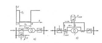
An idea of the diagnostic methods for power transformers is given by a stylized drawing (Fig. 1).
picture 1
When conducting surveys, the following types of surveys were used, which made it possible to carry out: 1) Control surveys: • promptly (100% coverage 1-2 times a year) to monitor the condition of the entire fleet of transformer equipment; • promptly identify, based on diagnostic results, the occurrence of gross defects; • raise in a timely manner the question of increasing the depth of examinations to expanded or comprehensive. 2) Extended examinations: • identify factors contributing to the accelerated development of defects in solid insulation and, as a consequence, reducing its service life; • establish the scope of additional diagnostic measures for the operation of the transformer; • justify the need for comprehensive surveys and determine the feasibility and scope of repair measures. 3) Comprehensive inspections: • assess the technical condition of the transformer and reasonably establish the service life and resource of the transformer in operation; • determine the volume and timing of repair and maintenance work. The main types of examinations and diagnostic methods for each type of examination of power transformers are given in Table 1.
Reliability of types of diagnostic examinations of transformers.
Data obtained in recent years from various types of surveys have made it possible to assess the reliability of the conclusion for several samples of transformers. 1. Reliability of diagnostics of block transformers.
Analysis of data on the reliability of diagnostics depending on the types of inspection (depth and number of methods) for block transformers shows that the reliability of assessing the technical condition of block transformers is as follows: • 40% of the equipment inspected is in the
“NORMAL”
, while for this group the volume of inspections increases the diagnosis does not change.
• 20% of “control”
reveal the presence of defects.
• 20% of “control”
do not reveal the presence of defects.
However, these defects appear during “extended”
examinations.
• 15% of “extended”
do not reveal defects, which are recorded only during
“comprehensive”
examination.
• For 85% of the equipment during the “extended”
examination, the conclusion is reliable.
2. Reliability of diagnosis of TSN
.
Analysis of data on the reliability of diagnostics depending on the types of examination (depth and number of methods) according to TSN shows: • 90% - defects are detected during diagnostics in the scope of an “extended”
examination.
• For 10% of the “extended”
examination, errors are possible.
As data analysis shows, monitoring discharge activity and especially their location makes it possible to quickly obtain the maximum amount of information about the presence of a defect and, mainly, about its dynamics. For this reason, circuits for measuring discharge activity are analyzed below.
Manufacturers.
The table below shows the factories that produce power transformers and occupy leading positions in the industry market.
| No. | Factory | Estimated production/delivery volume in 2007, units |
| 1 | Minsk Electrotechnical Plant named after. V.I. Kozlova | ~12000 |
| 2 | "Ukrelectroapparat", Khmelnitsky | ~ 1000…2000 |
| 3 | "Altrans", Barnaul | ~ 8000 |
| 4 | "ETK "BirZST", Birobidzhan | ~ 3000 |
| 5 | Kentau Transformer Plant, Kentau | ~ 2000 |
| 6 | JSC "Electroschit-TM", Samara | ~ 5000 |
| 7 | JSC "Electroshield" Moscow - Chekhov | ~ 5000 |
| Total power oil transformers | ~ 35000 |
Three-phase two-winding transformers 330 kV
Table 5.19
| Type | Snom, MBA | Regulation limits | Catalog data | Calculation data | |||||||
| Unom of windings, kV | IR, % | Pk, kW | Рх, kW | Iх, % | RT, Ohm | Xt, Ohm | Qx, kvar | ||||
| VN | NN | ||||||||||
| TRDNS-FOOOO/330 | 40 | +8×1,5 % | 330 | 6,3-6,3;6,3-10,5; 10,5-10,5 | 11 | 180 | 80 | 1,4 | 12,3 | 299 | 560 |
| TRDCN-63000/330 | 63 | +8×1,5 % | 330 | 6,3-6,3; 6,3-10,5; 10,5-10,5 | 11 | 265 | 120 | 0,7 | 7,3 | 190 | 441 |
| TDC- 125000/330 | 125 | — | 347 | 10,5; 13,8 | 11 | 360 | 145 | 0,5 | 2,78 | 106 | 625 |
| TDC-200000/330 | 200 | — | 347 | 13,8; 15,75; 18 | 11 | 560 | 220 | 0,45 | 1,68 | 66,2 | 900 |
| TDC-250000/330 | 250 | — | 347 | 13,8; 15,75 | 11 | 605 | 240 | 0,45 | 1,2 | 52,9 | 1125 |
| TTS-400000/330, TDTs-400000/330 | 400 | — | 347 | 15,75; 20 | 11 | 810 | 365 | 0,4 | 0,6 | 33 | 1600 |
| TC-630000/330 | 630 | — | 347 | 15,75; 20; 24 | 11 | 1300 | 405 | 0,35 | 0,4 | 21 | 2205 |
| TC-1000000/330 | 1000 | — | 347 | 24 | 11,5 | 2200 | 480 | 0,4 | 0,26 | 13,2 | 4000 |
| TC- 1250000/330 | 1250 | — | 347 | 24 | 14 | 2300 | 750 | 0,75 | 0,2 | 10,6 | 5375 |
Three-phase and single-phase autotransformers 330 kV
Table 5.20
| Type | Snom, MBA | Catalog data | Calculation data | ||||||||||||||||
| Unom of windings, kV | IR, % | Pk, kW | Рх, kW | Iх, % | RT, Ohm | Xt, Ohm | Qx, kvar | ||||||||||||
| VN | CH | NN | B-C | V-N | S-N | B-C | V-N | S-N | VN | CH | NN | VN | CH | NN | |||||
| ATDTsTN-125000/330/110 | 125 | 330 | 115 | 6,3; 10,5; 15,75; 38,5 | 10 | 35 | 24 | 370 | 115 | 0,5 | 1,3 | 1,3 | 2,6 | 91,5 | 0 | 213,4 | 625 | ||
| ATDTsTN-200000/330/110 | 200 | 330 | 115 | 6,6; 10,5; 38,5 | 10 | 34 | 22,5 | 600 | — | — | 180 | 0,5 | 0,8 | 0,8 | 2,0 | 58,5 | 0 | 126,6 | 1000 |
| ATDTsTN-250000/330/150 | 250 | 330 | 158 | 10,5; 38,5 | 10,5 | 54 | 42 | 660 | 490 | 400 | 165 | 0,5 | 1,07 | 0,08 | 4,3 | 49 | 0 | 186,2 | 1250 |
| ATDTsTN-240000/330/220 | 240 | 330 | 242 | 11; 38,5 | 7,3/ 9,6 | 70/ 74 | 60 | 430/ 560 | 260 | 250 | 130 | 0,5 | 0,4/ 0,53 | 0,4/ 0,53 | 7,3/ 7,2 | 39,2/ 59,2 | 0 | 2/8,4/ 312,1 | 1200 |
| AODTSTN- 133000/330/220 | 133 | 330/ 3 | 230/ 3 | 10,5; 38,5 | 9 | 60,4 | 48,5 | 280 | 125 | 105 | 55 | 0,15 | 0,62 | 0 | 3,5 | 28,7 | 0 | 136,5 | 599 |
Notes.
1. For AT, the power of the LV winding is 50% of the rated value, with the exception of AT with a power of 200 and 250, 240 and 133 MV-A, for which it is 40 and 25% of the rated value, respectively.
2. Voltage regulation is carried out on the MV side due to the on-load tap-changer ±6×2%, with the exception of AT with a power of 240 MB A, which does not have regulation
3. Since 2004, the group has been producing transformers with voltages of 330 kV and above.
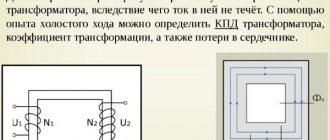
What is measured and indicated?
The power rating of transformers is measured in kVA (kilovolt-amperes), not kW (kilowatts). These two indicators are different and not identical. The first is the total (nominal) power, the second is the active. The rated power is not consumed in full, since part of it is distributed to the electromagnetic fields of the circuit, and only the remaining part - this is the active power - acts as intended.
The load on a transformer is determined by the current consumed, not the energy that is actually used. That is, the total power represents the entire voltage applied during operation of the device to all components of the electrical chain. Therefore, this nominal value is indicated in volt-ampere units.
In the operation of electrical appliances, a coefficient is also taken into account, which is expressed in the ratio of active to nominal (cos phi). This coefficient reflects the magnitude of the phase shift of the alternating current relative to the load applied to it.
Three-phase and single-phase two-winding transformers 500-750 kV
(without voltage regulation)
Table 5.21
| Type | Snom, MBA | Catalog data | Calculated data (for three phases) | |||||||
| Unom of windings, kV | IR, % | Pk, kW | Рх, kW | Iх, % | RT, Ohm | Xt, Ohm | Qx, kvar | |||
| VN | NN | |||||||||
| TDC-250000/500, TC-250000/500 | 250 | 525 | 15,75 | 13 | 600 . | 250 | 0,45 | 2,65 | 143 | 1125 |
| TDTs-400000/500, TTD-400000/500 | 400 | 525 | 13,8; 15,75; 20 | 13 | 800 | 350 | 0,4 | 1,4 | 89,5 | 1600 |
| TC-630000/500 | 630 | 525 | 15,75; 20; 24 | 14 | 1300 | 500 | 0,35 | 0,9 | 61,3 | 2205 |
| TC-1000000/500 | 1000 | 525 | 24 | 14,5 | 2000 | 600 | 0,38 | 0,55 | 40 | 3800 |
| OTs-533000/500* | 533 | 525/3 | 15,75; 24 | 13,5 | 1400 | 300 | 0,3 | 0,45 | 23,3 | 4797 |
| ORC-417000/750* | 417 | 787/3 | 20; 24 | 14 | 800 | 400 | 0,3 | 0,96 | 69,3 | 3753 |
* The LV winding is made split into two with a power of 50% each.
Three-phase and single-phase autotransformers 500-750-1150 kV
Table 5.22
| Type | Catalog data | Calculated data (for three phases) | |||||||||||||||||||
| Snom, MBA | Regulation limits | Unom of windings, kV | S windings, % | IR, % | Pk, kW | Рх, kW | Iх, % | RT, Ohm | Xt, Ohm | Qx, kvar | |||||||||||
| VN | CH | NN | VN | CH | NN | VN-SN | VN-NN | CH-NN | VN | CH | NN | VN | CH | NN | |||||||
| ATDTsTN-250000/500/110 | 250 | ±8×1.4% OLTC in HV neutral | 500 | 121 | 10,5; 11; 38,5 | 100 | 100 | 40 | 10,5 13 | 24 33 | 13 18,5 | 550 640 | 270 230 | 0,45 0,45 | 1,7 2,28 | 0,47 0,28 | 3,52 5,22 | 107,5 137,5 | 0 0 | 132,5 192,5 | 1125 1125 |
| ATDCTN- 500000/500/220 | 500 | ±8×1%; -8×1.25% on-load tap-changer in the MV line | 500 | 230 | 100 | 100 | 11,5 | 1050 | 230 | 0,3 | 1,05 | 1,05 | 57,5 | 1500 | |||||||
| AODTSTN — 167000/500/220 | 167 | ±6×2.1% on-load tap-changer in the MV line | 500/ 3 | 230/ 3 | 11; 13,8; 15,75; 20; 38,5 | 100 | 100 | 30; 40; 50 | 11 | 35 | 21,5 | 325 | 125 | 0,4 | 0,65 0,58 0,66 | 0,32 0,39 0,31 | 2,8 2,7 | 61,1 | 0 | 113,5 | 2004 |
| AODTSTN-167000/500/330 | 167 | ±8×1.5% on-load tap-changer in the MV line | 500/ 3 | 330/ 3 | 10,5; 38,7 | 100 | 100 | 20 | 9,5 | 67 | 61 | 320 | 70 | 0,3 | 0,48 | 0,48 | 2,4 | 38,8 | 0 | 296 | 1503 |
| AODTSTN — 267000/500/220 | 267 | ±8×1.4% on-load tap-changer in the MV line | 500/ 3 | 230/ 3 | 10,5; 15,5; 20,2 | 100 | 100 | 25; 30; 45 | 11,5 | 37 | 23 | 490 | 150 | 0,35 | 0,28 | 0,28 | 1,12; 0,9; 0,6 | 39,8 | 0 | 75,6 | 2803 |
| AODTSTN — 333000/750/330 | 333 | ±10% OLTC in MV line | 750/ 3 | 330/ 3 | 15,75 | 100 | 100 | 36 | 10 | 28 | 17 | 580 | 250 | 0,35 | 0,49 | 0,49 | 1,36 | 59,1 | 0 | 98,5 | 3497 |
| AODTSTN- 417000/750/500 | 417 | ±5% OLTC in HV neutral | 750/ 3 | 500/ 3 | 10,5; 15,75 | 100 | 100 | 12;8 | 11,5 | 81 | 68 | 700 | 280 | 0,2 | 0,12 | 0,12 | 2,2; 3,24 | 55,1 | 0 | 309 | 2502 |
| AODST-667000/1150/500 | 667 | — | 11503 | 500/ 3 | 20 | 100 | 100 | 27 | 11,5 | 35 | 22 | 1250 | 350 | 0,35 | 0,83 | 0,42 | 3,7 | 80,9 | 0 | 150,4 | 7004 |
Series control transformers
Table 5.23
| Snom, MBA | Regulating transformer type | Type of power autotransformer | Catalog data | Calculated data Qst, kvar | ||||||||
| Rated voltage of autotransformer, kV | Rated voltage of windings, kV | IR, % | Pk, kW | Рх, kW | Iх, % | |||||||
| VN | CH | NN | exciting | regulatory | ||||||||
| 240 | VRTDNU- 240000/35/35 | ATDTsTG-240000/220 ATDTsTG-240000/330 (ATDIT) | 230 230 | 121 121 | 11 38,5 | 11 38,5 | ±24,2 +24,9 —26,2 | 10,9-0-10,5 11,1-0-11,3 | 154 178 | 40 47 | 3,8 3,8 | 9120 9120 |
| 330 | 165 | 11 | 11 | ±33,8 | 11,8-0-11,8 | 183 | 40 | 3,8 | 9120 | |||
| 330 | 242 | 11 | 11 | +31,4 —33,1 | 10-0-10,1 | 85 | 30 | 4,0 | 9600 | |||
| 347 | 242 | AND | 11 | +38,3 —40,4 | 12,8-0-13 | 132 | 29 | 3,8 | 9120 | |||
| 347 | 242 | 38,5 | 38,5 | +24,9 —26,2 | 11,1-0-11,3 | 178 | 47 | 3,8 | 9120 | |||
| 92 | ODCGNP- 92000/150 | AODTSGN- 333000/750/330 | 750/ | 330/ | 15,75 | — | — | 6,67 | 185 | 110 | 0,7 | 644 |
Standard voltages
International standards in this area are developed by Technical Committee (TC) No. 8 of the International Electrotechnical Commission (IEC) “Standard voltages, currents and frequencies”.
General power supply systems used in various countries have a current frequency of 50 or 60 Hz. The frequency of 60 Hz is mainly used by the power systems of the American continent and its surrounding islands, some Asian countries (Japan, South Korea, Taiwan, the Philippines, Saudi Arabia, Bahrain) and one African country - Liberia. Some countries in these regions use both systems (Brazil, Bolivia, Japan, Bahrain, Guadeloupe). Low voltage voltages in these countries are typically 240/120V (America) or 200/100V (Japan and South Korea). The voltage for powering household electric motors is obtained by removing the midpoint of one of the phases and grounding it; The ED is connected to one of the phase arms. Single-phase electric power supply of industrial enterprises and powerful household equipment are connected to 240 V. Three-phase networks have voltages of 277/480 V and 347/600 V.
Most countries in the world use 50 Hz. In terms of low voltage voltages, these countries can be divided into two groups: those using voltage 220/380 V and 240/415 V. The latter voltage is used in the UK, Australia, New Zealand, Malaysia, New Guinea, Saudi Arabia, Kenya, Kuwait, Cyprus and some small island states that were former colonies of Great Britain.
For a long time, within the framework of TC No. 8, work was carried out to unify these voltages. Until 1975, in Publication 38 TC No. 8, both voltages were present as standard. Subsequently, a recommended voltage of 230/400 V was additionally introduced, and in 1983, the voltages 220/380 V and 240/415 V were eliminated and replaced with a single standard voltage of 230/400 V. The voltage of 380/660 V, mainly used in the USSR and Finland, replaced by 400/690 V.
This publication establishes a 20-year transition period, by the end of which (2003) all operating electrical equipment must have a rated voltage of 230/400 V, and operating voltages in electrical networks must be in the range of ±10% of the specified voltage.
From the very beginning of the transition period, the electrical industry must produce electric power supplies with a voltage of 230/400 V. In order for old and new electric power supplies to work normally in the general network, 418 restrictions are imposed on the operating voltage ranges in the networks: countries with voltages of 220/380 V reduce the lower limit from - 10% to -6%, and countries with 240/415 V voltages have an upper limit of +10% to +6%. During the transition period, both networks will operate with asymmetrical voltage tolerance ranges of 16% wide (10% in one direction and 6% in the other).
Within 20 years, the vast majority of old electronic devices will be replaced by new ones. At the end of the transition period, the operating voltage ranges of the networks can be expanded to ±10%, but already in relation to a voltage of 230/400 V.
In 1992, by direct application of the international standard IEC 38–83 “Standard voltages recommended by IEC”, GOST 29322–92 “Standard voltages” was introduced, establishing for distribution networks and power supply systems for AC consumers, as well as equipment operating in these systems , standard voltages 230/400 V and 400/690 V.
The development of the economic situation in Russia over the past 15 years has led to the fact that the majority of household electrical appliances began to be supplied from abroad (with a rated voltage of 230/400 V), their production by the domestic electrical industry practically disappeared, and the problem of low-voltage voltage compliance resolved itself .
Standard voltages of networks and equipment above 1000 V are established by GOST 721 “Rated voltages above 1000 V” (Table A8.1).
Table P8.1