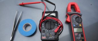
Among household and professional electronics devices, multimeters occupy a special place. Testers that determine the characteristics of electrical energy transmission circuits, line integrity, current values of current and voltage. A nice addition, for most models, is checking the circuit resistance and gain of pnp or npn transistors.
All of the above is available in the simplest and most inexpensive multimeters like the DT83x series. There are also more professional devices, such as Resanta DT9205A.
Unlike the 830s mentioned first, the multimeter from Resanta is more advanced in terms of tested characteristics. For example, they can additionally find out the capacitance of the capacitor and the strength of the alternating current. The quality of the device, its lightness, operating time and small dimensions, judging by user reviews, are quite worthy.
The DT9205A digital multimeter, last but not least, is distinguished by its relative unpretentiousness and accuracy of readings. A bonus is that the device is turned on with a button rather than a rotary control. The latter is quite convenient if you need to frequently measure one characteristic. Constant rotation of the selector, as part of selecting a procedure and turning on the device, soon leads to its wear and tear. Resanta is free from this problem.
Characteristics
Everything can be learned by comparison; the table will show the characteristics of two partially similar in functionality multimeters DT830 series and Resanta DT9205A.
| Characteristic | DT83x | Resanta DT9205A |
| Indication | Digital | Digital |
| Voltage constant | 200 mV–1000V | 200 mV–1000V |
| Voltage variable | 200 mV–750V | 200 mV–750V |
| DC current strength | 10 A, 200 mA–200 μA | 2 mA–20 A |
| AC power | No | 2 mA–20 A |
| Diode test function | Eat | Eat |
| Transistor testing | Eat | Eat |
| Sound signal | Eat | Eat |
| Resistance measurement | 200 Ohm–200 kOhm | 200 Ohm–2000 MOhm |
| Checking capacitors | No | 20 nF – 200 μF |
| Probe connection outputs | 3 | 4 |
| Transistor strip | Circular | Linear |
| Capacitor sample inputs | No | Eat |
| Nutrition | Krona battery, AA cells | Battery "Krona" |
| Dimensions* (mm) | 70×126×28 | 186×86×41 |
| Weight* (gram) | 137 | 315 |
| Price* (rubles) | 650 | 850 |
*may vary
How to use a multimeter
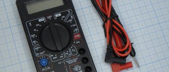
And today we will talk about how and what can be measured with a digital multimeter. For clarity, I will use the DT9205A model. But all of the above can be applied to most similar models, since they are very similar and differ only in some functions.
So, the DT9205A multimeter is designed to measure: - DC and AC voltage; — direct and alternating current; — resistance; — capacitor capacities; — continuity of diodes and transistors.
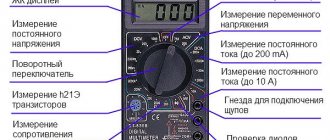
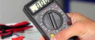
On the front panel we see a display. The maximum value that it can display is 1999. Below the display there are two buttons, one for turning on/off (ON/OFF), and the second for fixing readings (HOLD). It is also unimportant that the multimeter has an auto-off function, i.e. If it is not used for a long time, it turns off on its own. Next comes the circular range switch, which we will look at below. Under the switch there are sockets for measuring capacitance and transistors. Well, at the very bottom there are 4 connectors for connecting probes.
There is a fuse inside the device, which often blows if the current measurement range is incorrectly selected. Power is supplied from a 9V battery, commonly referred to as a “crown”.
Let us now consider everything in more detail. I think it’s only worth mentioning the on/off and recording buttons, since everything is obvious with them. Next, ranges. They come in both groups and singles. For ease of perception, they are painted in different colors. Let's look at them sequentially, moving clockwise.
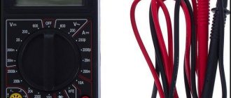
— The first group is resistance, it includes subranges for measuring Ohm (Ohms), kOhm (kiloOhms) and Mohm (megaOhms) and is indicated by the Ω icon. — The next group is constant tension. Subranges allow you to measure mV (milliVolts) and V (Volts). Indicated by the V- icon. - Directly behind her is a group of alternating voltage. Here everything is the same as in the previous group, you can measure mV (milliVolts) and V (Volts), BUT already alternating voltage. Indicated by the symbol V~. - The so-called single range - hFE (I haven’t found how to read it correctly), is intended for measuring the current gain for bipolar transistors. And directly below it is a socket where transistors are inserted. - Behind him again is a group - a container. It can be used to measure capacitors. Subranges allow you to measure both nF (nanoFarads) and μF (microFarads). The measurement socket is located just below. Indicated by the F icon. - Next, the group is DC. Subranges include mA (milliamps) and A (amps). Indicated by the symbol A-. — The next group is similar to the previous one, but is used to measure alternating current. The subranges are the same. They are indicated by the symbol A~. — And the last range is dialing. It is used to check the integrity of circuits (it beeps) and check diodes.
The next thing we need to look at is the bottom row of nests. The sockets work in pairs and are connected according to the figure. Red arrow - red probe, black - black.
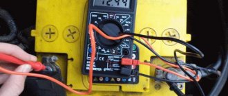
As for the measurements themselves, everything is simple. We find out what value we need to measure. Next, we set the switch to the maximum possible value (or a smaller one, provided that the maximum number of the subrange is greater than the value being measured), if necessary, rearrange the probes, and take measurements. If the measurement value is too small, select a smaller subrange. For example, we measure a regular battery with a voltage of 1.5 Volts. Having played it safe, we chose a subrange with a limit of 20 Volts; according to the readings, it is obvious that you can choose a smaller subrange, i.e. 2 Volts. This will make the readings more accurate. Sometimes it happens that in the process of measuring current in the 200 mA subrange, the current value turns out to be greater, as a result of which the fuse blows. After which, current measurement becomes impossible until the fuse is replaced.
Well, that seems to be all I wanted to say about measurements with a multimeter. Of course, there are many other models on the market, but they are all similar, so I think there is no point in describing them all, since they are all similar both in functionality and interface.
Appearance
Resanta DT9205 is made in a small plastic case, with a fairly large and clearly visible LCD display, which shows the identified characteristics. Below on the left is the work indicator. On the right is the power button. It happens that the location of the activation key has been changed, and the LED has been replaced with a Hold button.
Next is the dial for selecting the measurement mode. After it, there is a capacitor input and a strip or circular connector for connecting transistors. At the very bottom of the front side of the case there are four sockets for connecting probes.
Among the design colors, black prevails, with possible edging in yellow or any other bright color. The selector has a current distinction (DC/AC), marked on its scale with different tonal spectrum markers.
Types of device
All multimeters or multitesters are divided into two large subgroups:
- Analog . They are made in the form of a scale and arrow. When working with such a device, it is necessary to take into account the indicators of the established limit, which a professional electrician is well versed in.
- Digital . Modern options that show the value on a digital display, with a parameter switch knob or push-button control. Advanced versions have functions for reading parameters of capacitor capacitance, frequency and pulse duration.
Important! In conditions of strong radio interference and signal noise, only the analog version is used to obtain accurate values.
Notes on use
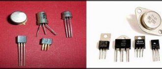
To the question of how to use a Resanta multimeter, there will be only one answer - operating the DT9205A is practically no different from a classic multimeter. The circular regulator selects a sector of the scale, depending on the type of measurement (resistance, capacitance, current, voltage, transistors, ringing), and the value within the limits that will be tested. If semiconductors or capacitors are being tested, the elements are placed in the device blocks intended for them. In the case of transistors, you need to pay attention to the correct position of the part along the base, emitter and collector in the contact pad. The input connector is marked accordingly, depending on the type of pnp or npn amplifier.
A description of methods for measuring various electrical quantities can be found here:
The resistance of resistors, lines, ringing and measurement of volts with current strength is carried out by the probes of the device. The latter are placed in the slots provided for this purpose at the bottom. Please note that milliamps and amps, as well as the measurement type, are different. The test probe is installed in the 20 A or mA socket to check the current strength within the appropriate limits. Voltage, resistance, or continuity testing is done by placing it in the jack marked "VΩ". The second probe is always located in “COM”.
How to use an analog multitester
The analog tester uses a general indicator to display the measured readings. On the scale behind the arrow there are several divisions: for volts, amperes and ohms.
The tester works on the principle of converting measured data into electricity, which creates a magnetic field, which in turn moves the needle. In this case, switching of input connectors and control of operating modes of the circuit is realized using a multifunction switch with buttons. A similar “handle” is also provided on digital versions.
Instructions for use of the analog tester
Let's look at how to use a dial multimeter and set it up to work:
- Check the batteries using a special mode.
- Perform a zero calibration. For these purposes, there is a tuning resistor, the handle of which is located on the front panel. It is also used when moving from one range to another. For example, changing the position from 10 Ohm to 10 Mohm, the spread is up to 25% of the scale length.
- Set AC or DC voltage. (The device contains a diode rectifier, since the magnetic head of the dial indicator functions only with direct current).
- Activate the shunt, which helps measure resistance over wide ranges on the sensing pointer mechanism.
- To select a measurement value, you must connect the device to the correct connectors, and you must observe the switching. If you do not follow all the rules for connecting to each section of the circuit where the current strength is different, the multimeter will fail.
- The connection between the device and the circuit is carried out using probes or clamps similar to crocodiles, which are named accordingly.
Important! During operation, do not touch exposed contacts with bare hands, even if the voltage seems safe.
Breakdowns and their correction
The cause of malfunction of any test device is often user inattention. However, most problems can be solved by repairing the DT9205A multimeter, with its full functionality restored.
| Sign | Cause | Solution methods |
| No readings after installing a charged capacitor in the multimeter connector | The operational amplifier chip LM324 burned out | Replacement with a similar one with four operational amplifiers. If accuracy is lost, you can correct the determination coefficient with a variable resistor located on the right-bottom of the front side of the board. |
| After checking the strength of a lot of ampere current in the microwave socket, the tester does not turn on | 0.5 A multimeter fuse blown | Changes to similar |
For other problems, you need to completely check the chain of electronic current flow according to the diagram, from the probe connector to the inputs of the main chip (under the drop). Included in the procedure is testing of all related parts - resistors and capacitors.
Structure of a multimeter
Before starting work, it is necessary to study the components of the device, because Instructions are not always included; we have prepared their description:
- Dial: Has arc-shaped scales visible through a glass or plastic display. The pointer on the display shows the scale values. If you use a digital multimeter (mastech mas838, ms8230b, m890d, dt700d, dt 9202a, 59002, mas830, my64), then its dial will be replaced by an LED display.
- Pointer or pointer: This is a thin black needle at the leftmost position in the dial window, designed to display measured data on pointer devices - yx 360trn, pmm 600, sunwa yx 1000a, m83. Before using a dial multimeter, be sure to read the instructions, especially the “division values” section.
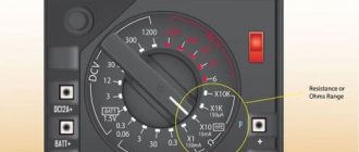
- Switch or button: Allows you to change the functions (voltmeter, ammeter, ohmmeter) and scale (x1, x10, etc.) of the meter. Many functions have multiple ranges, just like touch switches. It is important to have a full range of operating modes. Most meters use the type of knob shown in the picture, but there are others. Regardless, they work similarly. Some meters have an "Off" position that serves as a switch, while others have a separate button to turn the meter on. The meter should be set to the "Off" position when storing.
- Jacks or holes in the housing to insert probes. Most multimeters have multiple sockets. One is usually labeled COM or (-) for general and negative. To connect the black probe. The other terminal is labeled V (+) and the Omega symbol for Volts and Ohms, respectively, and positive charges. The + and - symbols represent the polarity of the probe when installing and testing the DC current value. If the test leads are installed according to the instructions, the red lead will be positive and the black lead will be negative. Many instruments have additional connectors that are required for high voltage testing.
- Test Leads with Clamps: The tester comes with 2 leads: one black and one red.
- Battery and fuse compartment: usually located on the back side. Fully charged batteries will be required for resistance and continuity of testing.
- Zero Adjustment: This small button is usually located near the dial called Ohm Adjust, 0 ADJ, or similar. Used only in ohmmeter or resistance range measurement mode while the sensors are closed, for example, to set the boiler thermostat.
Video review of working with a multimeter