The popularity of the Internet among the population is constantly growing. However, many people live in places where the signal is very weak or non-existent. In this regard, the problem of increasing the power and quality of Internet reception becomes very acute. Slow speed takes a lot of time and does not give the desired result. Therefore, an external Kharchenko antenna often comes to the rescue, designed in the form of a double square, the material for which is thick copper wire. The connection with a square to each other occurs in places of open corners, where the television cable is connected.
Such an antenna requires precise calculations for digital terrestrial television. To improve directionality, some designs may include a grating or continuous screen made of conductive material. Such a biquad antenna allows you to solve many problems with signal reception and Internet speed. Homemade structures, including various types of Kharchenko antennas, are relatively easy to make and include metal and plastic parts, as well as elements from other materials, connected in different ways. Similar designs can be easily made independently, including the Kharchenko antenna for TV with your own hands.
How a digital antenna for a TV works: I’ll explain it simply
Before you start assembling any of the four models of receiving antennas, you should have a good understanding of the processes that should take place in them.
Electromagnetic waves propagate in all directions of the horizon from the electrical signal transmitter generator installed on the television tower.
They have sufficient power for their coverage area, but their signal weakens as distance increases. Its magnitude is also affected by the terrain, various electrical and magnetic obstacles, and the state of the atmosphere.
In a vibrator oriented perpendicular to the movement of the electromagnetic wave, voltage is induced according to the laws of induction. The positive and negative half-waves of the harmonic create their own sign.
The voltage reaches its maximum value - amplitude at points of time corresponding to ¼ and ¾ of the period or 90 and 270 degrees from the sinusoid of electromagnetic wave intensity.
Any shape and size of active vibrators are created for the most effective voltage induction with minimal energy loss. The position of these points is calculated using the wavelength or harmonic frequency.
The voltage, closed to the internal resistance of the television receiver, generates an electric current in the created circuit. Its shape and direction change and proportionally repeat the signals of the transmitter on the active load.
Due to the use of various types of digital modulation on the transmitter side, information signals are received and processed within the television receiver circuit.
I will not go further into considering the question of how a digital antenna for a TV works during its creation.
What technical characteristics of the antenna determine the quality of TV signal reception?
The antenna is classified as a reversible device because it works the same on the transmitter and receiver sides. When analyzing the characteristics, its inclusion is used as a generator.
To effectively receive a digital signal, it is necessary to take into account that on the generator side, the emitter of electromagnetic waves can be positioned at any angle to the horizon, but only two directions are legally accepted: horizontal and vertical.
Our task is to repeat this orientation for our own TV.
The direction of polarization and other digital signal transmission data can be found on the operator’s website through a search engine.
We go to the website and select the required information.
We are primarily interested in 3 characteristics:
- channel number and its frequency, for which we will create an antenna according to strict dimensions;
- the radius of the transmitter service area, which affects the signal quality and the choice of vibrator design;
- direction of polarization.
The distance the TV is located from the transmitting tower greatly affects the design of the antenna.
The higher the antenna is installed, the better the quality of the received signal, but the length of the cable can weaken it significantly .
In this regard, residents of the upper floors of multi-story buildings have a significant advantage over their neighbors below. For a reliable reception zone, I tested the simplest Kharchenko models and loop assemblies made of coaxial cable and wire, which have a wide range of reception frequencies.
For long distances it is better to assemble a wave channel or a log-periodic circuit. Of the simple designs, the Turkin antenna, modified by Polyakov, has proven itself well.
For example, in my area the distance from the TV tower was 25 km, which is within the zone of reliable reception, and the signal frequency is 626 MHz of vertical polarization.
I calculate the length of the electromagnetic wave through the speed of light by frequency: λ=300/626=0.48 meters. The half wave will be 24 cm, and the quarter wave will be 12.
Based on these characteristics, I made 4 test antennas for digital television with my own hands, which I describe below.
3G modem accelerator using the program
There are a lot of programs on the RuNet to speed up a 3G modem. You can download this program from the manufacturer's website. It’s up to you, of course, but I already wrote an article “How to speed up a 3g modem with a program”, before downloading and not wasting your time, read about the 3g modem accelerator program.
I will now briefly describe to you how this program works. Using software compression of information, the Internet is accelerated. That is, the Internet accelerator, before loading a page or downloading any information, passes it through a special server, where it is all compressed. There is also a manual mode for setting up the Internet. Honestly, I don’t know, I’ve never tried to work with such programs, I don’t argue that this program can increase speed. For full functionality, you must send an SMS to speed up your modem; for more details, follow the link mentioned above.
How to make an antenna: step-by-step instructions
- Make marks on the wire with a marker or lightly notch it from start to finish at a distance of 15 cm from each other.
- Holding the conductor in a vice or using pliers, bend the wire at an angle of 90°. The fourth fold must be done in the opposite direction so that the square does not overlap the first. This will give us two diamonds.
- The free ends should not touch the other inside corner.
- Thoroughly clean the extreme ends of the wire with sandpaper or a file.
- Use acid and solder to solder the ends. You can pre-wrap the ends with wire to make soldering easier.
- Strip the antenna wire approximately 20 mm. Remove the top shell to this length. And remove the internal insulation by about 5 mm.
- Solder the shielding layer of the cable to one corner. Attach the copper cable core to the other by soldering.
- You can attach the cable to one or two sides of the Kharchenko device. Use duct tape or other adhesive material. But it is better to clamp the cable with plastic ties. The insulating tape will begin to peel off over time when exposed to moisture.
- The last step is to protect the center point of the antenna. Fill the center with epoxy or hot glue. Be sure to check that the inner corners do not close.
All that remains is to put the antenna plug on the cable and try to set up digital television on a T2 set-top box or TV.
Improved 3g reception
Modern mobile Internet uses the 3g standard with a signal frequency of 2100 MHz and a wavelength of 143 mm. Therefore, the dimensions will be as follows:
- L1 (outer side of the square) – 37.1 mm;
- L2 (inner side of the square) – 35.5 mm;
- L3 (frame length) – 104 mm;
- L4 (frame width) – 52 mm;
- L5 (connection gap) – 2.2 mm;
- D (height of racks) – 17 mm;
- B (screen width) – 148 mm;
- H (screen length) – 148 mm;
- wire diameter – 2.5 mm;
- quantity of wire – 305.4 mm.
Structurally, the 3g antenna is no different from the design for WiFi.
Connecting to a 3g modem
The most effective way is to connect the cable inside the router, but to do this you need to be a specialist in the field of repairing mobile communication equipment. For everyone else, we can suggest another method.
Wireless connection
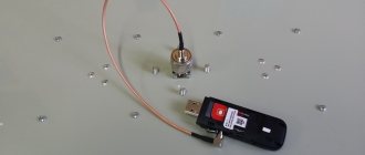
To do this, cut two pieces of copper or brass foil, 45 and 27 mm wide and long enough to wrap the modem and solder the edges. We do the same with a wide section, solder the central core of the cable to it and put it on the modem. Instead of a wide piece of foil, you can strip 15-20 cm of wire and wrap the modem tightly. A narrow piece is bent in a semicircle and soldered to the cable braid. The relative position for the best reception is selected experimentally.
Additional Information.
If the antenna is connected directly to the modem, without a cable, and the modem itself is connected using a USB extension cable, then losses in the cable can be avoided.
Connect to a smartphone or tablet
It is necessary to strip a piece of cable and wrap the central conductor 10-15 turns around the phone. You can also take a piece of brass or copper foil, solder the central core of the cable to it and insert it between the back cover and the case.
Installation and connection
The connection diagrams for the finished antenna differ and depend on which device it is connected to.
You can connect the finished structure to the modem in 2 ways, depending on whether it has a connector for an external antenna. The task is simplified if there is one. In this case, you need to select a plug that matches the type of connector on the modem and solder it to the free end of the coaxial cable in the manner described in paragraph 4 of the instructions for assembling an antenna for digital TV. After this, all that remains is to connect the plug to the connector built into the modem.
The task becomes more complicated, but not much, if the modem does not have a connector. First, you need to disassemble the device to get to the printed circuit board. There will be a contact or track on it that acts as an antenna, to which you need to solder the central core of the cable. The braid is soldered to the modem body or to its grounding. To maximize connection speed, the structure should be rotated so that it faces the tower. All that remains is to connect the modem to the laptop and check the signal reception level.
Installation and connection to digital TV is carried out taking into account the polarization of the television broadcast wave. If the received signal is horizontally polarized, the structure should be rotated so that the vibrators are located vertically, that is, one above the other. If the polarization is vertical, the biquadrates are placed horizontally in the form of an infinity sign. The structure is directed towards the television tower. The antenna is connected to the receiver (receiver) using a plug.
To connect the “double square” to a cell phone, you need to remove the cover of the device and find a socket for an external antenna. The connection is best made through an adapter or antenna adapter, on one side of which there is a connector for connecting to the phone socket, and on the other side there is a standard high-frequency connector. The plug of the assembled antenna is connected to it.
Antenna for Wi-Fi.
Principle of operation
An electromagnetic wave of a sinusoidal shape propagates in space in two planes: horizontal and vertical. They are called signals with horizontal and vertical polarization. The receiving antenna must be oriented depending on the type of polarization. For horizontal polarization, the biquadrates must be arranged in a figure eight; for vertical polarization, they must form an infinity sign.
Correct orientation in space allows you to achieve optimal reception quality. Electromagnetic signals are sent from the transmitter emitters to the TV antenna at high frequencies. When an electromagnetic wave passes through the surface of the vibrators, a voltage appears in it, which is applied to the power points. Under its influence, currents arise on the metal elements of the antenna, which form an electromagnetic field. It is amplified and sent to the TV, where it is converted into image and sound.
DIY antenna.
Various schemes for making the Kharchenko antenna
On the Internet you can find many different schemes for assembling Kharchenko antennas. So that the dear reader does not bother himself with searching for them, we offer our selection, which includes the most workable options.
PHOTO:
PHOTO:
PHOTO:
How to make a reflector
A reflector is a metal surface that is needed to reflect a signal. If it is not made, the signal will pass past the antenna and be absorbed by the wall. The reflector will reflect the radio signal back to the antenna conductor. This allows you to strengthen the signal.
Made only from conductive material. As materials you can take:
- solid metal sheet;
- fiberglass, which is used for the manufacture of printed circuit boards (covered with a layer of copper foil);
- metal lattice like a cage for parrots or rodents;
- You can build it yourself from a board by gluing regular foil to one side.
The reflector area should be approximately 20-30: larger than the dimensions of the Kharchenko biquadrat. Therefore, the sides of the “reflector” must protrude.
An interesting solution is a cut piece from the computer system unit case.
The figure eight must be fixed to the reflector through insulating material. Short circuit is not allowed. Can be attached through a piece of PVC pipe, marker shell, or other non-conductive material.
The distance from the reflector to the Kharchenko rhombus should be 7 times less than the length of the side. If we take the calculation given earlier, then the distance will be 15/7 = 2.1 cm.
Kharchenko antenna for digital TV: how confidently it works
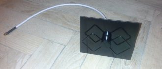
I show a general view of the structure I assembled with a photograph. Taking vertical polarization into account, it is arranged in a figure eight shape, and for horizontal orientation it is rotated like a butterfly.
For clarity, I turned it over: with a screen in the center of the transmission and with an active vibrator made of a copper bus - in the room.
The television cable is simply tied with electrical tape on one side of the square, secured to a stand and in my case also serves as a fastening element: it is simply thrown over the eaves - the antenna hangs on it.
Many neighbors have already repeated my project. I can see it with this window treatment.
People even hang figure eight on curtains; they have started to do it without a screen or mounting rail - an active vibrator confidently gives the reception. This makes assembly easier. However, in case of extraneous interference, I recommend assembling the screen.
I conclude that the Kharchenko antenna works quite reliably in a reliable reception area. Since its calculation and installation are simple and does not require scarce parts, I recommend assembly.
How to calculate the dimensions of an antenna for digital television with your own hands in simple ways
To determine the size of Kharchenko’s room, I found a lot of tips that, to put it mildly, are not suitable, but work. In the photo I show only 3 calculation methods.
There are also online calculators that calculate different sizes. I explain all this by the fact that such a design is not critical for manufacturing accuracy, which I consider to be an advantage.
For testing, I chose a technique in which the side of the square is equal to 0.25 wavelengths of the electromagnetic oscillation. Less material is required here, and the working conditions are the most difficult.
I multiply the wavelength 48 by 0.25 and get a side of a square of 12 cm.
And then I will show you a technology that will not be difficult for you to repeat. But I still recommend expanding the side of the square a little.
It will then begin to capture a slightly wider range of signals due to the fact that this form of vibrator handles all the amplitudes of the voltage half-waves that are inserted into it. This ensures its broadband access.
How to make a Kharchenko antenna: personal experience of “assembling on your knees” with photographs
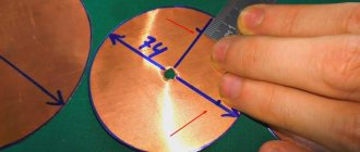
The active vibrator is made from a copper busbar with a rectangular section of 1x4 mm.
This profile is difficult to bend. You have to work in a vice. The round section is easier to work with. I cleaned the middle part of the paint and soldered the contact pads with a soldering iron.
On one side of the square, I tied the coaxial cable with electrical tape and soldered its conductors to the prepared areas.
Due to the created half-ring, the adaptation angle of the wave impedances of the cable and antenna is formed. This is the simplest design. But she plays an important role.
I show this connection with other photos on the finished antenna.
Next, I just have to make a shielding grid that blocks extraneous signals from the opposite side so that they do not interfere with the reception of information.
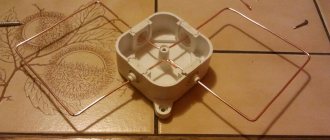
I marked the wooden plank and drilled several small holes.
I inserted pieces of wire into them, the length of which slightly overlaps the area of the active vibrator, and blocked them with matches. You can add more glue.
The result is this Kharchenko antenna for digital TV with a cable connected to it.
Here I show his position on the window while working last summer.
And I recently took this photo: I show it from a different angle.
At the moment, I have already given up using the DVB T2 digital TV antenna after connecting fiber optics and switched to the Beltelecom package.
Description of a homemade receiver
With appropriate settings, a homemade 3G antenna or together with a biquad antenna can simultaneously act as a receiver and amplifier. Biquadrat is a type of loop antenna that is part of the zigzag group. It was invented by Russian scientist Vladimir Kharchenko. It was first used in the second half of the 20th century to “catch” signals from television broadcasts. Scientists tuned this device to a frequency of 14 MHz, gave it the required position and began to receive signals from the United States of America.
Note! Today, a biquad panel antenna for 3G can be bought in a specialized store, or you can make such a simple device yourself.
According to numerous calculations and experiments by V. Kharchenko, according to the output, even a do-it-yourself antenna for the Internet helps to enhance the operation of digital devices that operate on mobile platforms. Without a reflector, signal reception increases to 4-5 dB, and with its implementation the indicator increases to 7-10 dB.
Antenna assembly
Manufacturing a Kharchenko antenna for digital television broadcasting involves the following step-by-step steps:
- The polarization and frequency of the wave are determined. The design must be linear.
- To manufacture a biquad receiver antenna, copper is used as a material. All elements are located at the corners, one of them must touch. For horizontal polarization, the structure must be positioned vertically. With vertical polarization, the device is placed on its side.
- The copper wire is measured and taken to the required length (+1 cm). A copper or aluminum tube (diameter 12 mm) is suitable. The insulation from the copper core is cleaned. Leveled with a hammer on a hard surface. The middle is measured and bent 90 degrees. If there is a vice, the wire is clamped and aligned in it. Bends are made according to the calculated dimensions.
- A small piece is cut off at one end at a 45 degree angle to form a pointed tip. The second end is bent and the same procedure is performed on it. Both squares can be slightly bent. Small cuts are made using a needle file on the central internal bends. Then it will be possible to pull these two loose ends together and secure them with a thin copper wire.
- You will need a soldering iron, as well as liquid rosin or flux for tinning the middle bends. This is done on each side of the copper wire.
- The coaxial cable is stripped 4-5 cm. The braid or outer conductor is twisted into one wire and wrapped around one of the bends. Solder it to a copper wire. The insulation of the inner conductor is stripped and similarly wrapped around the next bend. Soldering must be done carefully, supporting the insulation with pliers, because it can move to the side due to heat. First, the frame at the sealing site heats up, and then only the conductor.
- The cable wiring is fixed with a nylon tie and degreased with a solvent.
The sealing areas are insulated with hot glue using a gun. To correct defects in adhesive formation, you can use a hair dryer. Visually, the internal central corners of the figure-eight structure should be close to each other (10-12 mm), but not touching. If there is an error when bending the contour even by 1 mm, the picture may be distorted. - The cable is brought to the approach points on both sides. One direction of the diagram must be blocked, for this purpose a copper reflective screen is installed. It fits onto the cable braid.
- To make a reflector, textolite boards coated with copper were previously used. Nowadays metal plates are used for this. The reflector can also be made from a grill grate. You can use a heat exchanger from a refrigerator or a dish drying rack. The main thing is that the structure does not rust in the open air. The reflector should be larger in size than the vibrator frame.
- The frame is located in the middle of the reflector. To secure it, you can use two metal plates.
- The high-frequency signal propagates over the surface of the conductor, so it is better to cover the antenna with paint. The sealing areas are filled with hot melt adhesive or sealant.
The receiver must be located from the reflector at a distance calculated by the formula: wavelength/7. The antenna is placed in the direction of the repeater.
How to make the correct calculations and make a Kharchenko antenna is shown in this video:
The first option is directional devices
When there is a signal on the 3G modem, but it is not strong enough, then you can get by with quite simple devices in order to achieve better quality of mobile Internet reception.
Typically, this measure consists of better positioning the modem and pointing its standard antenna in the desired direction (towards the tower). An ordinary tin can, an old pan, dishes, or even a simple disc may be suitable for these purposes.
For example, if we talk about a can antenna, then you only need to punch a hole at the base or in the bottom in which the modem itself would be securely attached. In fact, the signal should be significantly stronger if you choose the right direction.
An example of a homemade can antenna
Those who use old disks to amplify the signal do it even simpler. The main thing is that they are opaque. But you shouldn’t expect great achievements from this method.
If you need to make the signal a little better
No special engineering skills are required if you adapt old dishes to enhance signal reception. Colanders or saucepans with handles work especially well. Then you can attach a USB cable to the handle, and move the modem itself a little into the inside of the dish, something like this:
Another simple way to improve signal reception with a 3G modem
Purpose and design of the Kharchenko antenna
This receiver is universal and equally effective for broadcasting and the Internet. But if for the latter, quality only affects the speed of data reception and transmission, then for digital TV accuracy is important, because The quality of the image depends on this.
Externally, it is a zigzag antenna with a reflector - a solid or lattice screen (frame) made of conductive material. To assemble it yourself, you need to observe geometric characteristics and choose a specific material.
Initially, it was created to receive the Internet, for which the final parameters were only a matter of speed. With the advent of digital television, a number of TV experts refer to its ineffectiveness. However, this is a mistake expressed by a skeptical attitude towards the characteristics.
Calculation of the Kharchenko antenna
If you correctly calculate the antenna dimensions, you will be able to watch all 20 free digital channels in the Russian Federation. And in Moscow and parts of the Moscow Region, where the signal from the Ostankino TV tower reaches, all 30 channels will be shown. Also, a third multiplex (channel package) is available in Crimea.
You can calculate it manually using simple formulas and repeater parameters from a digital television card. Or use a calculator to calculate. In the latter case, the final values for sizing will be much more accurate. In addition, getting dimensions with a calculator is much faster and easier. The calculator is in the next section of the article.
To calculate the length of the wire and understand where to make bends, follow the step-by-step algorithm below.
- First you need to find out the frequency at which the TV signal is transmitted by the tower in your region or where you need to set up channels. To do this, open the CETV card.
- In the “Address or facility” line, write the full address, be sure to include the house number. Click on the "Find" button.
- The mapping service will show with an arrow where the indicated house is located. Click on it, after which the characteristics of the television towers will be displayed. These are the two closest towers that broadcast in the specified area.
- Choose a tower, preferably one that is located closer. Look at the "Direction" line.
- Now you need to take the frequencies of both multiplexes and subtract the average.
For future calculations, fictitious values will be taken to make it easier. I take values of 400 and 600 MHz. The arithmetic mean is (600+400)/2=500 MHz.
We use the formula to calculate the wavelength (λ):
Where
- λ—wavelength;
- C – speed of light (3*108 m/s);
- F is the average frequency calculated a few lines earlier (500 MHz).
We find that the length of the wire for making one square (rhombus) is λ = 300/500 ≈ 0.6 m ≈ 60 cm.
The first number 300 is the converted speed of light in seconds.
Since the obtained value is the length of the conductor of one part of Kharchenko, the total length of the wire will be twice as large, that is, 60 * 2 = 120 cm.
And the side of the square is four times less than the length of the entire square, i.e. L = 60/4 = 15 cm.
Now we clearly understand at what distance the bends need to be made and what length of wire is needed.
By the way, it is better to take the wire 1-2 cm longer in order to make a slight bend at the ends. This will make it easier to solder and attach the coaxial cable.
Mobile Internet or satellite?
Just 15 years ago, the only source for suburban Internet was satellite Internet.
There were entire communities and forums where connection technologies, signal stability, cost of services on different satellites, etc. were discussed.
But now that's all in the past. Satellite Internet, as well as satellite television, are quietly living out their last years, so IMHO there is no point in looking in this direction.
A real alternative to wireless Internet access in almost any area are the so-called “opsos” - cellular operators that offer fast, simple and relatively cheap mobile Internet in 2G/3G/4G formats and, in the future, 5G .
The cellular communication format determines, first of all, the data transfer speed. That is, from practice, the average speeds are:
2G - approximately 30-40 Kb/s in the EDGE standard. 3G - approximately 500-800 Kb/s in the UMTS+ standard 4G - approximately 2-5 Mb/s 5G - planned around 1 Gb/s, implementation can be expected no earlier than 2020.
Moreover, these speeds will increase, since there is a theoretical reserve of bandwidth and the same 3G Internet can deliver up to 21 Mbit/s (more than 2 Mb/s), and the 4G standard - theoretically up to 1 Gbit/s (more than 100 Mb/s) , it’s just that the technical capabilities of opsos do not yet allow them to implement all this for their subscribers.
Year after year, mobile Internet is becoming cheaper, more stable and faster, so it makes sense to bet on it now.
At the time of writing, the most popular format (generally the fastest in Belarus) is 3G, it covers most of the country, and 4G is just starting to be tested in Minsk, although 4G networks are already in full use in Russia.
Required materials and tools
Kharchenko's DIY television antenna for DVB T2 is quite economical. In order to assemble the structure, you will need the following parts:
- Wire;
- Coaxial cable;
- Wooden slats.
As for tools: pliers, hammer, sharp knife. If you plan to attach the antenna device to a wall or other surface, you will most likely need a drill for mounting.
"Double" Bi-Quad (double biquad)
Double biquadrat is also a Kharchenko antenna. It is made with your own hands in the same way as a regular biquadrat. It differs from a regular biquadrat in that at the vertices of the squares, instead of the corners, there are additional squares. The dimensions of these squares are exactly the same as the main ones. Therefore, no additional calculation is needed; you can take the calculation for a regular biquadrat. The calculation for the Kharchenko antenna can be found in this article or use the online calculator program for the calculation. The wires at the intersection are insulated from each other.
The double biquadrat can be continued in the same way. Those who want to make it can easily calculate the length of the wire. This gives additional gain.
Using small homemade directional antennas, you can receive a signal at a distance of up to 2 kilometers. These homemade products are a good replacement for expensive solutions.
Materials and elements for assembly
To assemble a Kharchenko antenna with a reflector you will need:
- a coil of wire made of conductive material, wire diameter about 2.5-3 mm;
- a piece of coaxial cable with a characteristic impedance of 50 or 75 ohms;
- antenna connector;
- metal plate;
- CD or DVD;
- plates or brackets for fastening;
- plastic bottle cap;
- insulating tape;
- glue;
- pliers;
- soldering iron
DIY TV antenna.
Improved 4g reception
Mobile Internet of the 4g standard uses a frequency of 2600 MHz with a wavelength of 115 mm. Therefore, the dimensions will be:
- L1 (outer side of the square) – 28.9 mm;
- L2 (inner side of the square) – 27.6 mm;
- L3 (frame length) – 81 mm;
- L4 (frame width) – 40.5 mm;
- L5 (connection gap) – 1.7 mm;
- D (height of racks) – 13.2 mm;
- B (screen width) – 115 mm;
- H (screen length) – 115 mm;
- wire diameter – 2 mm;
- quantity of wire – 237.9 mm.
Evolution
The antenna, invented by Kharchenko, is a double square made of thick copper wire. The squares are connected to each other with open corners, and at this point the television cable is connected to them. To improve directionality, a grille made of conductive material is installed at the rear. The perimeter of each square is equal to the wavelength to which the reception is tuned. The diameter of the wire for 1-5 television channels should be about 12 cm. Because of this, for radio communications and meter range television (1-12 channels) it turns out to be very cumbersome.
To facilitate the design, a gasket with three wires of a smaller cross-section was used, but it still had a lot of weight and dimensions. The zigzag antenna created by Kharchenko received a second life when broadcasting appeared in the UHF range. Everyone remembers rhombuses, circles, triangles and other homemade figures as a TV antenna for receiving decimeter waves, which hung on many people’s balconies and outside their windows. They were one of the signs of that time.
In 2001, Professor Trevor Marshall (USA) proposed using this design in Bluetooth and WiFi networks.
Decimeter version
A design feature of the Kharchenko antenna is a fixed ratio between the perimeter of each of its two squares and the length of the received waves (they must be equal). To obtain the required induced field strength, it is also important to select the correct diameter of the frame wire. Since broadcasting was previously focused on the meter range, receiving such a signal would require a wire with a diameter of about 12 cm.
In this case, the zigzag antenna would be too bulky and inconvenient to use, and its dimensions would not allow it to be used at home. Kharchenko’s zigzag antennas experienced their second birth at the time of the advent of broadcasting in the decimeter bands. A zigzag antenna designed to receive a UHF signal must have fixed dimensions, which will be discussed in the following sections.
Related material: How to make an antenna for 4G.
The characteristic impedance for which such home-made structures are calculated is usually about 50 Ohms. This indicator, however, agrees well with a typical coaxial line with a corresponding parameter of 50 (75) Ohms. To expand the bandwidth of the television signal, such an antenna was made not from a simple wire, but from a flat copper or aluminum bus, the individual parts of which were connected into a biquadrate using pre-selected aluminum rivets.
At the junctions of the copper strips, the UHF antenna was additionally soldered; in this case, the distance between the rivets was taken as its length. In cases where, in order to obtain reliable reception, it was necessary to use a standard antenna amplifier, the developers did without the second square (one was enough for reliable reception).
Decimeter version of the antenna.
Improving WiFi and Bluetooth quality
It is known that the WiFi signal is transmitted, like other types of terrestrial communications, over a radio channel, which allows the use of an antenna design to improve the reception of a router or similar devices. According to a number of craftsmen from among the developers of 3g antennas, if in the design discussed above a parabolic dish is taken as a screen, the gain at WiFi frequencies can be increased to 31 dB.
Such a screen can be made from a tin can bent in a certain way. When making a reflector for 3g or WiFi, the curvature of its surface is usually selected experimentally. To do this, a program must be installed on the transmitting/receiving device (router, for example) that can record the level of the signal entering the device. Using such a program, it will be possible, by changing the curvature of the surface of a homemade screen, to monitor all changes in the gain (in real time).
Kharchenko antenna for different types of signals.
Improving Internet connection speed with Kharchenko antenna
Today, digital television goes hand in hand with Internet technologies. Among television lovers, there are viewers who prefer watching from a computer monitor via the Internet. But this requires high speed, because... In Internet broadcasting, the digital signal is not encoded and information is transmitted in large quantities.
This problem is relevant only for owners of 3G modems, which will be considered:
- Owners of 4G modems with an extremely weak connection exchange information at a speed of 5+ Mb/sec, which will only make them wait longer to download a game or movie.
- The technical speed of 3G modems (3-6 Mb/sec) is borderline for using modern Internet functions. With a weak received signal, the speed on a 3G network is no more than 1 Mb/sec, at which it is no longer possible to watch a live broadcast in Full-HD quality or play online games with good graphics.
A Kharchenko antenna with your own hands will help increase the connection speed when the computer is far from the television tower and solve the problem of the inconveniences described above. The modem does not require strict adherence to accuracy when assembling it, and the error will only slightly degrade the speed.
Calculation
3G modems operate at a frequency of 1.9 - 2.1 GHz, taking into account which it will be necessary to make a universal receiver. The principle of calculating the sides of biquadrates is the same as for watching digital television; instead of multiplex frequencies, the minimum and maximum values of the frequency range are used.
In which modems work:
- ƛmin = 300/2100 = 0.143 m = 143 mm;
- ƛmax = 300/1900 = 0.158 m = 158 mm.
It was reported above that the length of the side of a biquadrate (zigzag) is half the width of the wave projected across the receiver, or ¼ of its length.
The result is:
- 143/4 = 35.75 mm for sides shortened by the gap;
- 158/4 = 39.5 mm for the other two sides.
Assembly
The receiver is assembled according to the same scheme designed for digital TV. If you don't have a soldering tool, you can use fasteners. The ends of both workpieces are connected by a conductive element. The design for the 3G modem is ready.
All that remains is to make a reflector, for which the same rules apply as in the manufacture of an antenna that picks up a DVB-T2 signal. The distance between the reflector and the receiver will be L = 158/7 = 22.57 mm or 2.5 cm. Given the small distance, one should not rely on the permissible error created by the thickness of the conductor. This is the recommended distance between it and the reflector. A cable with a resistance of 50 - 65 Ohms is soldered to the finished antenna at any point of the receiver.
Connection
With rare exceptions, 3G modems do not have a connector and it is impossible to use external antennas with them. If there is one, connect the plug to the cable and everything is ready. If it is missing, you need to disassemble the modem. The cable core is soldered to one of the contacts connected to the USB input, and the wire from the reflector is soldered to ground (the outer side of the input).
In what cases is an antenna needed for a modem?
The antenna will improve the mobile Internet if the signal icon shows two or even separation. External antenna accessories pick up signals where the built-in antenna cannot. If there is no signal, it is likely that the external antenna is also powerless in your case.
Many modems have a side connector for connecting a cable from an external antenna
If the problem is only in speed, there are a lot of bars, most likely the reason is that the operator’s base station is overloaded with requests from subscribers. Even if you install an antenna, the speed will not increase. In this case, it is recommended to change the operator or try to point the antenna towards another company tower.
Tests
approximate
with a stated gain of 11dBi
USB extension cable for 3G modem transfer speed
When you buy a wireless modem, you are given an additional extension cord for it. I had it, of course, in a short size of 30 cm. This is of course not enough, preferably you need 2-3 meters. I personally don’t really need it, but for those who live in remote parts of the city, this will be just the thing. Having connected the cord to the computer, we take it in the direction where the radio antenna of the cellular operator should approximately be located. This method works in many cases and is also very simple and does not require much effort or skill.
Making a biquad antenna with your own hands
The time required for assembling the structure is a maximum of 1 hour. If you know how to handle tools, and have at least some skill in assembling other structures, you can do it in 30-40 minutes. Elements for the structure can often be found at home. As a last resort, the components can be easily purchased at the radio market or at a hardware store.
Materials and tools
Main list:
- copper wire with a cross-section of 1.5-5 mm (it is better not to use an aluminum conductor or other material, since it is difficult to solder on them, and these places directly affect signal loss);
- coaxial cable with a resistance of 75 Ohms (for digital television broadcasting), 3-5 m long (depending on the location of the antenna, the further the installation is from the TV, the longer the cable will be);
- pliers to bend the wire in the right places if the material is thick and making bends with your hands is problematic;
- material for cleaning the places to which the cable will be connected (file or sandpaper);
- tape measure, centimeter or ruler to accurately measure the length of the element;
- soldering iron, materials for easy and high-quality soldering (rosin, tin);
- F-plug, which is mounted on the second end of the cable and inserted into the antenna connector of the TV.
If the antenna is installed on the roof of a private house, you may need a long wooden, plastic or even metal bar. It will serve as a matcha on which Kharchenko’s design will be fixed.
To protect connections when installed outside buildings, it is better to protect the antenna from moisture. The easiest way to wrap the joint and solder joints is with electrical tape. This option is simple, since the electrical tape can be torn off at any time and access to the connections. An option that will reliably close the connections (but tightly) is to fill them with epoxy resin, silicone sealant, hot melt adhesive or varnish.
Manual calculation
You don’t have to calculate the antenna for T2, but then you are not sure that you will be able to watch digital channels at all. Therefore, you need to have accurate data; this will allow you to catch at least 20 channels in your region. Thirty channels (the third multiplex) can only be watched in Moscow, the region and Crimea.
Let's perform the calculation using the example of the city of St. Petersburg.
- First you should find out the frequencies of the channel numbers that are broadcast in the region. Since the biquad antenna must operate in both frequency ranges, you need to find out the channel frequency of the first and second multiplex. Based on the parameters of the repeaters on the TsETV map, the first multiplex (TVK 35) broadcasts at a frequency of 586 MHz, and the second operates at a frequency of 666 MHz (TVK 45).
Using the same map you can find out your frequencies yourself. Enter your exact address in the search bar and click on your home on the map. - Determine the average value. This will make it possible to make the antenna in an intermediate design and catch the radio signal from both multiplexes at once. We calculate the arithmetic average: (586+666)/2=626 MHz. The value will be used in further calculations.
We calculate the length using the formula: λ = c/F, where
- λ is the desired wavelength;
- C – speed of light (3*108 m/s, which is equal to 300 s);
- F – average frequency determined earlier (626 MHz).
If we substitute the available values into the formula, we get the following:
λ = 300/626 ≈ 0.4792 m ≈ 47.92 cm.
This is a figure that is equal to the length of the copper conductor to make one diamond.
In practice, when making a “biquadrat”, such dimensions can become very large. It is allowed to take a smaller value, exactly two or four times.
We have:
- λ = 47.92 cm/2 = 23.96 cm;
- or λ = 47.92 cm/4 = 11.98 cm.
Now it’s worth calculating the length of each side of the rhombus. We will use the original value of 47.92 cm.
- This means that the side will be equal to L = 47.92/4 = 11.98 cm ≈ 12 cm.
- The total length required to bend the entire antenna (two diamonds) of wire is 47.92*2 = 95.84 cm ≈ 96 cm.
Kharchenko antenna calculator
Instead of manual calculations, you can find out the most accurate dimensions of a digital antenna using the online calculator below. All you need to do is enter the average frequency in the first field of the calculator. Next, click on the “Calculate” button and the calculator will immediately display the final parameters. The advantage of the calculator is that it performs a full calculation, and not just determining the size of the outer side of the vibrator.
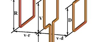
All dimensions are indicated in millimeters. The required values are indicated on the left in the figure.
Changing network settings to speed up the 3G modem
The quality of communication depends on the settings, which is a parameter such as MTU - the maximum block size that receives and sends information. Windows defaults to the default value (usually 1500). Which I will write in the next article: setting parameters. Or there are programs - tests that can be used to determine the mtu parameter. But I haven't heard of them yet.
PS Personally, I tried one more method. I took a 3 meter USB extension cord and placed it on an aluminum cup, but so that the antenna from the modem (Fig. 3) touched this cup. And wa-la, the speed has become much faster. Yes, someone in the comments said that he hung a chain, I tried my own (silver one), the result was ineffective, but it depends on everyone.
Rating 3.4 out of 5. Votes: 9
| RSS |
| << Begin < Previous 1 2 3 4 5 6 7 8 9 10 Next > Last >> << Begin < Previous 1 2 3 4 5 6 7 8 9 10 Next > Last >> |
| Alexander - Branded antenna | |2017-05-18 13:38:15 |
| Answer |
| Anonymous | |2016-01-17 19:15:08 |
| Answer |
| krotov - bolts on the modem | |2017-01-18 03:44:35 |
| There are special screwdrivers for this. Take the set, it will come in handy) |
| Valery - antennas | |2015-08-07 01:52:57 |
| Answer |
| stas | |2015-06-17 17:53:00 |
| Answer |
| Yuri - author - how to seal a wire? | |2015-06-18 19:04:56 |
| Answer |
| MAX | |2015-04-20 20:27:13 |
| Answer |
| VICTOR - MODEM AMPLIFIER | |2015-01-03 20:23:51 |
| Answer |
| Yuri - I CAN’T DISASSEMBLE THE MODEM | |2015-01-12 19:59:39 |
| Answer |
| cap - antenna | |2014-12-19 11:43:16 |
| Answer |
| Seryoga - modem | |2014-07-24 00:57:07 |
| Answer |
| Anonymously | |2014-01-09 00:13:26 |
| Answer |
| Petrov - Antenna socket | |2013-12-01 02:41:55 |
| Answer |
| Yuri - Antenna socket in the modem | |2013-12-01 12:09:29 |
| Answer |
| Bekzat - Antennas | |2013-11-29 21:39:55 |
| Answer |
| Julia - speed | |2013-09-28 22:50:00 |
| Answer |
| Yuri - speed 50kbps | |2013-09-30 10:04:58 |
| Answer |
| Mikhail - an aluminum sink will do | |2013-08-18 03:57:51 |
| Answer |
| Mikhail - will there be a difference? | |2013-08-18 03:35:12 |
| Answer |
| Alexei | |2013-08-05 23:09:45 |
| Answer |