If we compare the receiving qualities of homemade antennas, then the best solution in terms of “ease of manufacture/level of reception” is the Kharchenko antenna. The design in the circle of radio engineers is also called: biquadrate, double square, figure eight, zigzag, zigzag antenna, double zigzag, diamond-shaped, double diamond.
The disadvantage of the design is the need for calculations. Otherwise, the antenna will not pick up the digital signal. But the calculation is quite simple, and there is an online calculator in the article below. This will allow you to get the desired values in one click.
Antenna properties
The Kharchenko antenna is intended for digital TV, but can also pick up an analog signal. Consequently, it will be possible to configure the TV to receive not only digital broadcasting, but also find analogue channels.
The antenna received a similar name due to its design. Outwardly it resembles two connected squares or rhombuses.
The big advantage is versatility. In addition to receiving terrestrial television signals, it can be used to work with mobile communications and Wi-Fi. Manufacturing in this case is no different. You just need to make it in different sizes.
The biquadrat receives signals from more distant repeaters than a beer can or cable antenna (loop). And it’s done in almost the same complexity. The cost of creating an antenna is low, and in some cases it is even produced free of charge. All you need is a copper conductor, which will act as the signal receiving element.
What is needed for production
To make an antenna with your own hands you will need:
- copper wire with a thickness of 1.5 to 5 mm;
- antenna cable with a resistance of 75 Ohms (standard value for TV signal transmission), the length of the wire depends on the location of the antenna (the further away, the longer the length);
- measuring instrument (ruler, centimeter or tape measure);
- pliers or a vice to bend the wire evenly;
- a soldering iron to connect the inner ends of the biquadrate to each other and to the television cable;
- F-type connector for installing an adapter on the second end of the cable to connect to a TV or set-top box;
- insulating material to protect connections from external influences if installation is done outside the building (insulating tape, epoxy resin, varnish, hot melt adhesive).
Depending on the installation location, material may be required to construct the fastening. For example, if Kharchenko’s structure is placed on the roof of a private house, then a mast can be made. In this case, you can use plastic pipes or wooden blocks.
Wire antenna: the easiest assembly for a TV
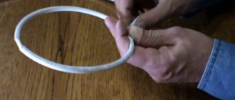
You can receive a digital signal on a TV in a zone of up to 30 km using a simple single or double ring of copper wire taken with a 2.5 mm square piece of electrical wiring.
I show the technology of assembling it from two rings. If you are interested in a simplified version, then do not mount the second element.
The circumference of the ring must correspond to the wavelength of the TV signal from the transmitter. In my example, this is 48 cm. I bite off two pieces of wire: L1 and L2 with a centimeter margin for connecting the ends.
I bend future vibrators into rings and clean their ends. On a short section I make small rings to connect the second workpiece.
I insert one vibrator into another and squeeze the rings with pliers.
I show this process on a larger scale.
I prepare the end of the coaxial cable for connection by stripping the insulation.
I twist all the ends.
I solder the joints with a soldering iron.
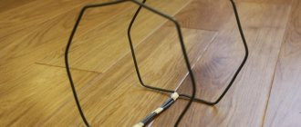
The result is a simple antenna made of wire, consisting of two rings.
It should be oriented with the side of the long wire facing the transmitter. The rings can be bent into a hexagon shape. Then they will take a more stable position.
The photo below simply shows the principle: I did not give special accuracy to the dimensions of the geometric figure. Do better for yourself.
The antenna is assembled from wire. We turn it on and check the quality of the received signal on the TV.
Any soft toy will help to add decorative properties to the structure. This antenna should be located near the TV or receiver. It is undesirable to exceed the length of the coaxial cable by more than half a meter.
You need to spend less than 10 minutes to assemble such a structure, it does not present any difficulties, like the previous scheme, and its operation is due to the assembled loop.
Calculation of the Kharchenko antenna
If you correctly calculate the antenna dimensions, you will be able to watch all 20 free digital channels in the Russian Federation. And in Moscow and parts of the Moscow Region, where the signal from the Ostankino TV tower reaches, all 30 channels will be shown. Also, a third multiplex (channel package) is available in Crimea.
You can calculate it manually using simple formulas and repeater parameters from a digital television card. Or use a calculator to calculate. In the latter case, the final values for sizing will be much more accurate. In addition, getting dimensions with a calculator is much faster and easier. The calculator is in the next section of the article.
To calculate the length of the wire and understand where to make bends, follow the step-by-step algorithm below.
- First you need to find out the frequency at which the TV signal is transmitted by the tower in your region or where you need to set up channels. To do this, open the CETV card.
- In the “Address or facility” line, write the full address, be sure to include the house number. Click on the "Find" button.
- The mapping service will show with an arrow where the indicated house is located. Click on it, after which the characteristics of the television towers will be displayed. These are the two closest towers that broadcast in the specified area.
- Choose a tower, preferably one that is located closer. Look at the "Direction" line.
- Now you need to take the frequencies of both multiplexes and subtract the average.
For future calculations, fictitious values will be taken to make it easier. I take values of 400 and 600 MHz. The arithmetic mean is (600+400)/2=500 MHz.
We use the formula to calculate the wavelength (λ):
λ = c/F, where
- λ—wavelength;
- C – speed of light (3*108 m/s);
- F is the average frequency calculated a few lines earlier (500 MHz).
We find that the length of the wire for making one square (rhombus) is λ = 300/500 ≈ 0.6 m ≈ 60 cm.
The first number 300 is the converted speed of light in seconds.
Since the obtained value is the length of the conductor of one part of Kharchenko, the total length of the wire will be twice as large, that is, 60 * 2 = 120 cm.
And the side of the square is four times less than the length of the entire square, i.e. L = 60/4 = 15 cm.
Now we clearly understand at what distance the bends need to be made and what length of wire is needed.
By the way, it is better to take the wire 1-2 cm longer in order to make a slight bend at the ends. This will make it easier to solder and attach the coaxial cable.
Evolution
The antenna, invented by Kharchenko, is a double square made of thick copper wire. The squares are connected to each other with open corners, and at this point the television cable is connected to them. To improve directionality, a grille made of conductive material is installed at the rear. The perimeter of each square is equal to the wavelength to which the reception is tuned. The diameter of the wire for 1-5 television channels should be about 12 cm. Because of this, for radio communications and meter range television (1-12 channels) it turns out to be very cumbersome.
To facilitate the design, a gasket with three wires of a smaller cross-section was used, but it still had a lot of weight and dimensions. The zigzag antenna created by Kharchenko received a second life when broadcasting appeared in the UHF range. Everyone remembers rhombuses, circles, triangles and other homemade figures as a TV antenna for receiving decimeter waves, which hung on many people’s balconies and outside their windows. They were one of the signs of that time.
In 2001, Professor Trevor Marshall (USA) proposed using this design in Bluetooth and WiFi networks.
Decimeter version
A design feature of the Kharchenko antenna is a fixed ratio between the perimeter of each of its two squares and the length of the received waves (they must be equal). To obtain the required induced field strength, it is also important to select the correct diameter of the frame wire. Since broadcasting was previously focused on the meter range, receiving such a signal would require a wire with a diameter of about 12 cm.
In this case, the zigzag antenna would be too bulky and inconvenient to use, and its dimensions would not allow it to be used at home. Kharchenko’s zigzag antennas experienced their second birth at the time of the advent of broadcasting in the decimeter bands. A zigzag antenna designed to receive a UHF signal must have fixed dimensions, which will be discussed in the following sections.
Related material: How to make an antenna for 4G.
The characteristic impedance for which such home-made structures are calculated is usually about 50 Ohms. This indicator, however, agrees well with a typical coaxial line with a corresponding parameter of 50 (75) Ohms. To expand the bandwidth of the television signal, such an antenna was made not from a simple wire, but from a flat copper or aluminum bus, the individual parts of which were connected into a biquadrate using pre-selected aluminum rivets.
At the junctions of the copper strips, the UHF antenna was additionally soldered; in this case, the distance between the rivets was taken as its length. In cases where, in order to obtain reliable reception, it was necessary to use a standard antenna amplifier, the developers did without the second square (one was enough for reliable reception).
Decimeter version of the antenna.
Execution in the DVB-T2 standard
Digital broadcasting, designated by the “dvb t2” standard, is carried out, as is known, at UHF frequencies corresponding to TV channels from 21 to 69, using the “multiplex” format. In many Russian cities, local television stations are gradually switching to the dvb TV broadcast format, which is causing some interest in ensuring its reliable reception.
In this regard, the user must know that a homemade design for T2 must have the same dimensions as a classic antenna for UHF digital broadcasting. Modern television receivers, which include an antenna for a digital signal, can weaken it if the transmitting station is close.
In special situations, when the transmitter for the T2 band is very close, when using the old frame design, you will either have to completely remove the second square (or screen), or choose a less sensitive amplifier.
The following solutions can be chosen as options for manufacturing a dcv structure:
- Make a completely new receiver for t2 with your own hands;
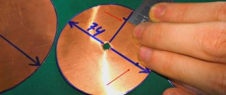
- Try to build a combined antenna containing an element in the form of a circle made of wire 55.5 cm long (see photo below);
- With its help it will be possible to receive all known formats (including 3g mobile communications).
It will be interesting➡ How to check the magnetron for serviceability with a multimeter
In the case when you need to make a structure for receiving Internet signals, including Bluetooth, WiFi (3g, 4g) or mobile communication channels operating on ultra-short waves, the dimensions of such an antenna will be very miniature.
Kharchenko antenna made of two circles.
Due to the high frequency, the dimensions of the antenna for 3g will be limited to a length of 10 centimeters, and all possible varieties of a homemade product can be assembled using the same drawing. Significant differences regarding all possible versions of a miniature antenna (for Bluetooth or for a cell phone) will appear only in the dimensions of the receiving structure itself. The calculation procedure in this case is determined by the method of using a specific network resource (these methods are widely represented on the network for both T2 and other TV signal formats).
Improving WiFi and Bluetooth quality
It is known that the WiFi signal is transmitted, like other types of terrestrial communications, over a radio channel, which allows the use of an antenna design to improve the reception of a router or similar devices. According to a number of craftsmen from among the developers of 3g antennas, if in the design discussed above a parabolic dish is taken as a screen, the gain at WiFi frequencies can be increased to 31 dB.
Such a screen can be made from a tin can bent in a certain way. When making a reflector for 3g or WiFi, the curvature of its surface is usually selected experimentally. To do this, a program must be installed on the transmitting/receiving device (router, for example) that can record the level of the signal entering the device. Using such a program, it will be possible, by changing the curvature of the surface of a homemade screen, to monitor all changes in the gain (in real time).
Kharchenko antenna for different types of signals.
How to make an antenna: step-by-step instructions
- Make marks on the wire with a marker or lightly notch it from start to finish at a distance of 15 cm from each other.
- Holding the conductor in a vice or using pliers, bend the wire at an angle of 90°. The fourth fold must be done in the opposite direction so that the square does not overlap the first. This will give us two diamonds.
- The free ends should not touch the other inside corner.
- Thoroughly clean the extreme ends of the wire with sandpaper or a file.
- Use acid and solder to solder the ends. You can pre-wrap the ends with wire to make soldering easier.
- Strip the antenna wire approximately 20 mm. Remove the top shell to this length. And remove the internal insulation by about 5 mm.
- Solder the shielding layer of the cable to one corner. Attach the copper cable core to the other by soldering.
- You can attach the cable to one or two sides of the Kharchenko device. Use duct tape or other adhesive material. But it is better to clamp the cable with plastic ties. The insulating tape will begin to peel off over time when exposed to moisture.
- The last step is to protect the center point of the antenna. Fill the center with epoxy or hot glue. Be sure to check that the inner corners do not close.
All that remains is to put the antenna plug on the cable and try to set up digital television on a T2 set-top box or TV.
How to connect the plug
- Use a knife to remove 1 cm of outer insulation.
- Loosen the braid and bend the screen back.
- Remove the insulation that covers the core by 7-8 mm.
- Start screwing on the F-connector by hand. You need to screw it in until the screen is completely under the connector. The core should protrude slightly from the connector hole. If it sticks out a lot, shorten the wire with wire cutters or scissors. If screwing is difficult, clamp the connector with pliers.
- Screw the adapter into the connector thread. You can connect the antenna to your TV.
If the TV is hung on a regular fixed bracket, then the distance between the case and the wall will be minimal. This almost always makes it difficult to insert the plug into the TV socket. Therefore, it is better to use an angled (V-shaped) antenna adapter rather than a straight one.
What you need to make an antenna
1) We need a piece of antenna cable, about 30 cm long.
2) Antenna connectors, the so-called F - connector and male - female connector.
F - connector and male-female
3) Tools: a knife, wire cutters, a calculator and, of course, a tape measure (or a ruler).
Connecting and setting up the antenna
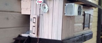
- Install a "double square" outside or inside the room.
Internal location is allowed only if there is direct visibility of the signal and there are no strong obstacles to the tower.
Use the instructions for correct antenna installation to point the structure as accurately as possible at the DVB-T signal broadcaster
- Stretch the cable to the TV and insert the plug into the antenna input of the device.
- Try auto-searching for channels.
If the antenna for receiving digital TV channels is made correctly, the search will find at least 10 channels. If the signal arrives over a wide area and arrives at a high level, then the TV will find two dozen TV programs.
Other options
Design option for Sotnikov's antenna made of three squares.
The options considered are not the only possible ones. There are many antenna designs for receiving television signals.
The following can be distinguished:
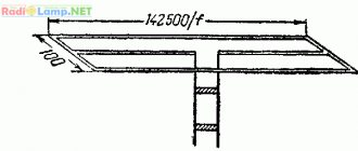
- Three-element wave channel. It is a rather complex structure of a horizontal strip on which two transverse stripes and a T-shaped frame are installed. A variant of this design is a four-element wave channel containing three crossbars and one T-shaped structure.
- Double square (Sotnikov antenna). It has a gain of 10–13 dB, consists of two square frames located parallel and connected to each other by a crossbar. A variant of the design is a triple square, the author of which belongs to the same Sotnikov. The amplification capacity is higher - around 14–15 dB.
- Turkin antenna. The gain of this design is more than 15 dB. It consists of six rings of different diameters, mounted on a horizontal dielectric support rod. The device requires a fairly careful calculation of the diameter of the rings and the distance between them.
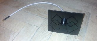
How to make a reflector
A reflector is a metal surface that is needed to reflect a signal. If it is not made, the signal will pass past the antenna and be absorbed by the wall. The reflector will reflect the radio signal back to the antenna conductor. This allows you to strengthen the signal.
Made only from conductive material. As materials you can take:
- solid metal sheet;
- fiberglass, which is used for the manufacture of printed circuit boards (covered with a layer of copper foil);
- metal lattice like a cage for parrots or rodents;
- You can build it yourself from a board by gluing regular foil to one side.
The reflector area should be approximately 20-30: larger than the dimensions of the Kharchenko biquadrat. Therefore, the sides of the “reflector” must protrude.
An interesting solution is a cut piece from the computer system unit case.
The figure eight must be fixed to the reflector through insulating material. Short circuit is not allowed. Can be attached through a piece of PVC pipe, marker shell, or other non-conductive material.
The distance from the reflector to the Kharchenko rhombus should be 7 times less than the length of the side. If we take the calculation given earlier, then the distance will be 15/7 = 2.1 cm.
Amplifier connection
There will be no problems connecting an external amplifier. This is a device that is cut into the cable by screwing into two F-connectors at the ends of the connecting cables. Mounted only indoors as close to the antenna as possible. Therefore, you should connect it immediately as soon as the cable is brought into the apartment.
As for the built-in amplifier (board), it is connected directly to the antenna outputs, i.e. to the internal ends. There are some minor difficulties, since there are contacts on the board that cannot be closed. Therefore, on the side of the board used for connection, you need to place, for example, a piece of thin rubber. The material prevents the contacts of the conductors of the on-air receiver from shorting.
The cable itself is soldered to the board outputs. Or it is mounted with a clamp mount, if one is present on the board. By the way, this is the best option, easier to implement and more reliable. The cable is stripped according to the standard procedure. And after installation, excess parts are cut off to avoid short circuits with other contacts.
Both with and without an amplifier, the central area can be protected with a plastic box. The payment requires mandatory protection.
The amplifier needs power. Voltage can be supplied in two ways:
- set-top box, then the power is turned on in the receiver settings;
- external power supply if the set-top box is not used. The TV itself cannot supply power, so a unit feeding the antenna is connected.
To turn on the feed on the set-top box, you need to go to the search menu and switch the corresponding option to the on state.
But the power supply should be connected to the side of the cable that is inserted into the television socket (or set-top boxes).
A wire comes out of the block, at the end of which there is a separator. You need to unscrew the device, strip the cable, insert it into the clamp and tighten the bolts.
Next, the separator plug is inserted into the antenna input, and the unit is plugged into the socket. Afterwards, you can tune in and watch digital TV channels.
Yagi does not require setup
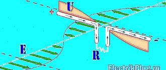
It turns out that you can create a wave channel that does not require configuration. Most descriptions of channel-wave antennas (Yagi) include a Gamma or Omega matching device, since it is assumed that the antenna has a characteristic impedance less than the characteristic impedance of the feed line, which is usually 50 or 75 Ohm coaxial cable.
In the process of modeling antennas using the program, I found out that it is possible to design an antenna with a characteristic impedance of 50 ohms, which exactly matches the cable impedance, and then there is no need for a matching device. Perhaps others have known this “discovery” of mine for a long time. What does this give? Firstly, adjusting gamma or omega is a troublesome task. Secondly, gamma or omega are frequency-dependent elements and therefore can “shade” the tuning (adjustment) of the antenna elements and even narrow its operating range. So why is this range used? It is needed when the wave impedance of the antenna is less than 50 Ohms. Why do less? Yes, this happens naturally in the process of tuning the antenna, which traditionally consisted of adjusting the length of the reflector in order to achieve maximum suppression of the back lobe of the radiation pattern and adjusting the length of the director (directors) in order to obtain maximum gain. After several tests (sometimes dozens), it was possible to obtain a successful combination of these parameters, and then this antenna received recognition, was published and even received a name, for example, UA4IF squares, K2PV Yagi, etc. However, local conditions were not taken into account. For example, if there is a terrain slope of 2-3 degrees, you can get more gain in this direction than from adding one or even two directors. Let's return to the properties of the antenna. As the size of the director approaches the size of the emitter, the antenna gain increases, its resistance decreases, and the operating frequency band narrows:
If we take into account that the matching device also has an operating band, which may not coincide with the operating frequency band of the antenna, then the picture will be worse than we see in the figure for options R1=25 Ohm and R2=12.5 Ohm. If you have to adjust the SWR not at the operating frequency of the antenna, and then raise the antenna, then the resonant frequency will definitely shift kilohertz by 100. For an antenna R3 = 50 Ohms, this is not so dangerous, since at frequencies +/- 100 kHz from the resonant frequency its SWR is still small , and for antennas with a narrower operating range this resonance shift may be unacceptable.
Gain (middle line), back-to-front ratio (dashed line) and SWR (lower solid line) versus frequency for a 50 ohm antenna:
The same parameters for the antenna R=12.5 Ohm. The first antenna has significantly greater uniformity of parameters across the range. True, with the second antenna you can surprise your colleagues with greater suppression of the back lobe at a frequency of 14.090 MHz:
In real conditions, due to the influence of the ground, the antenna forms a lobe radiation pattern, the shape of which, among other things, depends on the height of the antenna above the ground. We will assume the suspension height is equal to one wavelength:
Note that the value of the gain in real conditions is significantly higher than in free space (in our case 14.1 dBi for ant R3 = 12.5), while the difference in gain for our three antennas is basically preserved:
If the increase from 6.9 to 8.5 dBi seems large, then in real conditions the difference between 12.5 dBi (ant R3 = 50) and 14.1 dBi (R1 = 12.5) no longer seems so significant. The significant thing is that the elevation angle of the main lobe for all three antennas remains the same, 14 degrees. At the same time, antenna No. 3 with R = 50 Ohm is better matched at the edges of the range, and therefore “receives” power from the transmitter better.
Now let's use the YO (Yagi optimiser) program to see the properties of antennas for long-distance communications. We will assume that long-distance communications are carried out at a radiation angle of 5 degrees to the horizon, as is the default in the program, although this value can be changed. Let us also remember that all three of our antennas have maximum radiation at an angle of 14 degrees. The gains of antennas 1, 2 and 3 at a radiation angle of 5 degrees are respectively 4.38 dBd, 4.96 dBd and 5.79 dBd. If the difference in gain between antennas 1 and 3 in free space is 1.66 dBi, and with a suspension height of l it is 1.61 dBi, then at an angle of 5 degrees it decreases to 1.41 dBd. It can be assumed that the calculations are simply not very accurate, but the trend can still be traced: when working with distant correspondents, the gain increase due to changes in the length of the elements is less than usually indicated in the antenna characteristics, i.e. free space gain.
Summarizing the above, we can say that the gain of the antenna is not the only or main criterion for its quality, and this means antenna options with the same number of elements and the same traverse length.
Broadband and minimizing television interference are sometimes considered important properties.
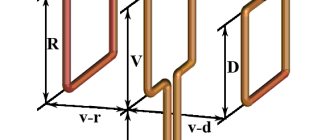
For an antenna with a split vibrator, a matching device can be proposed for some fixed values of characteristic impedance, namely, for 37.5 Ohm and 25 Ohm. The device consists of two pieces of cable connected in series with a length of l/12 (electrical length, not physical dimensions). The section of cable closest to the antenna has a characteristic impedance of the power line (ours is 50 Ohms), and the next section is the antenna impedance, i.e. 37.5 or 25 Ohm. Such resistances can be obtained by connecting two pieces of cable in parallel: 75/2=37.5 or 50/2=25. The device is compact, does not require setup and is easily protected from atmospheric influences.
There are two versions of Yagi: with elements isolated from the traverse and with non-insulated elements. In the latter case, Quick Yagi can correct for the length of the elements. True, a split vibrator must be insulated, otherwise it becomes “continuous”.
Summarizing the above, we can recommend the following procedure for designing and building an antenna. 1. We set ourselves the ultimate goal: what kind of antenna do we need? - A. broadband antenna covering both SSB and CW sections of the range. At the same time, we have no desire (or opportunity) to lower the antenna for adjustment. Then an antenna with a characteristic impedance of 50 Ohms and low gain is best suited. - b. It is possible to lower the antenna for adjustment in case of deviation from the specified parameters. Then we set the resistance to 35 Ohms with an average gain. - V. we need a narrowband antenna for the telegraph section with maximum gain. We set the resistance to 25 Ohms to achieve a high gain. 2. How many elements should the antenna have? If the length of the traverse (boom) is less than 0.4 wavelengths, then there is no point in making more than 3 elements. If we set a resistance of 50 Ohms, then it is better to take the “Reflector-vibrator” distance at least 0.15 dl. waves, and at R = 25-35 Ohm it is better to take smaller ones. 3. We launch the program in automatic or manual design mode with a given number of directors (possibly with the number “0” for two elements). 4. Launch the gain optimization mode. We get a result with a resistance of 27-35 Ohms. 5. Enable bandwidth optimization with the “wide” parameter. The resistance will increase slightly. 6. We begin to manually edit the antenna dimensions to achieve the EXACT value of the desired resistance. We vary the sizes of the reflector and director (directors), as well as the distances, periodically checking the resulting radiation pattern and SWR curve. You can design several antennas with the same impedance and, after comparing other characteristics, choose the best one. 7. After manufacturing and installation, we measure the resistance. If it corresponds to the design, then there is no need to check anything else, all other parameters will also work out. If the resistance differs from the calculated one, it is necessary to simulate on a computer how much the length of the director needs to be changed (and which director, if there is more than one). This is usually a small amount. There is no need to make any suppression or gain settings, this can only worsen the antenna parameters.
For those wishing to model Yagi on a computer, I would advise using the WA7RAI program (link given above), and not MMANA, which is more universal, but in the case of Yagi it is weaker than the specialized QUICK YAGI program.
An antenna with a split vibrator can be used at frequencies other than its resonant frequency. The simplest way is to simply adjust the P-circuit of the transmitter. In this case, of course, one should not expect maximum efficiency, and interference with television is quite possible. However, for some combinations F(ant)+F(tx) you can get good results. For example, an antenna for 18.1 MHz worked without TV interference at a frequency of 24.9 MHz and worse at 21 MHz. But this method is unacceptable for modern transceivers, despite the presence of a tuner - don’t take the risk! You can achieve an SWR of no more than 1.5 at the output of the transmitter by connecting a short-circuited loop to the cable, the length of which together with the cable must be a multiple of l / 2 minus half the length of the split vibrator L = l / 2 * n - L1:
Here l is the wavelength to which we want to adjust the antenna; L1 – half the length of the vibrator of the tunable antenna. The distance to the connection point can be calculated using the nomograms presented by Rothhammel for short-circuited loops. You can use a remote tuner with a large impedance tuning range.
If we rebuild the antenna for 28 MHz (its radiating element) to a frequency of 24.9 MHz, then its reflector will now work as a director, and the maximum radiation will be in the opposite direction to that which was at 28 MHz.
Antenna radiation patterns R=50 Ohm at three frequencies: 14,000, 14,150 and 14,250 MHz:
the same for the antenna R=12.5 Ohm:
Working with the QUICK YAGI (Qy4) program
Launched in DOS or FAR (Windows DOS emulator) with the file qy4.exe Opens the first page of the menu: Auto mode menu - automatic design Manual entry - manual entry With tapered el's - with elements of variable diameter
The arrow command is the default. Pressing the initial letter of a command (A, M or W) executes that command Bottom: Ctrl+Q : Quit = exit the program (Y-Yes, No-No) Esc : To Main = go to the main menu F1 : files = call up files antennas from memory F2 : Options = options
When you press the A key, we enter the submenu of the auto-design menu Auto-Options auto mode settings Spacing (Directors) - distances (directors) Length (Directors) - length (directors) Default len & space - default length and distances Auto design of Yagi - auto-design of Yagi
When you press A in this submenu, we enter the auto-design mode Optimized Spacing - optimized distances Max FB & Bandwidth - maximum forward/backward ratio and bandwidth (W/Default Spacings) (with default distances) Tab: Tapered diameters N stepped diameter - by pressing the Tab key, toggle No - Yes Spacebar: View changes N viewing changes - by pressing the spacebar, toggle No - Yes
For example, leave both parameters No and press the “Enter” key
A line appears: OPERATING FREQUENCY Enter 14.2 and “Enter” Will all elements be the same diameter? “Y” “Enter” # of directors – number of directors 1 “Enter” EL DIAM, mm – diameter of elements in mm 30 “Enter” the antenna project appears with element lengths, distances, as well as parameters in the right window: FORWARD GAIN F TO B RATIO INPUT IMPEDANCE 25.8 +j 11.2 Ohm (25.8 active resistance + 11.2 reactive component) ARRAY LENGTH (antenna length in meters) In the lower right window: Select Optimize (select an optimization parameter) Best gain/pattern - the best gain/suppression ratio Spacing only - distances only Lengths only - lengths only For example, select “B” and the following appears: Select Target F/B (select the desired suppression) A 35 B 30 C 25 For example, select 25 and press C: Choose Bandwidth Wide appears - wide Average - normal No changes - no changes Press W and get the final antenna design with a reactive component value of 0. Now you can write this data using the F1 (file) key: Get saved files - call the file from the saved ones Save this file - save this file Print this file - print this file Delete a file - delete the file Press S: Enter a FILE name (8 letters max) 20M3ELE (we set the name 20M3ELE) “Enter” The file name appears in the lower window and the ability to cancel by pressing Esc “Enter” - saved.
Now we can edit the data manually, for example, to adjust the resistance to 50 or 25 ohms. We can change the lengths of the director and reflector, as well as changing the distances. In this case, each time you can view not only the numerical values of gain and suppression, but also the SWR, gain and suppression curves depending on frequency. You can save various options and then select the desired one, or simply observe the influence of various parameters on the properties of the antenna.
We type 10.8 “Enter” in the reflector window, 9.4 “Enter” in the director window. We get: Input Impedance 51 +j 0.5 Ohm
To remove the reactive component of 0.5 Ohm, we do optimization, for which we press F4 and a submenu appears: Bandwidth - band width Driven element - active element Gain / FB / Pattern - amplification / suppression / diagram Press “D” and the program changes the length of the active element so, that j=0, and the resistance of 50.9 Ohms is purely active (at a given frequency) Press F3 and look at the diagram in the horizontal plane (at a given frequency) Press Esc and return to the menu. Press F6 and get a table of parameters depending on the frequency. At the bottom we see a line of commands: P: print (print) G: graph (graphs) B: BW plot (frequency pattern) Esc: exit Press G and get a combined graph of SWR, gain and suppression depending on frequency. Let's look at the F2 option again. Submenu: Change to Ft/In – change meters to feet/inches Fed element options – parameters of the active element Scaler – scaling (by ranges) Element compensation – compensation of elements (if not isolated from the traverse) Press F: Simple dipole – simple dipole Folded dipole – loop vibrator Exit no change – exit without changes
You can exit the program and run the QYUTILS.EXE file. There is a calculation for the gamma matcher, although I have not tried it, since I prefer a split vibrator, which eliminates reactive elements such as capacitors and reduces TV interference.
Well, in general, try different modes. The program is written very competently and is resistant to non-standard situations. After a little practice, you will understand that it is 10 times easier than MMANA and gives 10 times more accurate results.
UA9OS
RELATED ARTICLES ON THE TOPIC:
- HF Yagi antenna (Yagi) from fishing rods The use of fiberglass for the manufacture of collinear VHF antennas and “square” spacers is a common occurrence. Often, fishing rods are used for these purposes, which at the end of the season are not so expensive compared to duralumin pipes (non-ferrous metal!). In addition, the rods have a good “action” from a mechanical point of view...
- Simple technology for manufacturing directional Yagi antennas In 1996...1998. Oleg, RV3TH, developed broadband 6- and 8-element Yagi with linear split vibrator excitation, operating in the range of 130..155 MHz. However, some difficulties arose with the implementation of the amateur radio version of the antennas. The fact is that the developer did not want to “get involved” with the metal boom as a whole...
- Antenna construction. 6 Yagi elements for 10m range A well-known Russian proverb says: “Prepare your sleigh in the summer...” During the years of minimum solar activity, it is time to think about a good antenna for the 10m range. Well, for contesting enthusiasts, good antennas for all bands are simply a must. Carrying out his own plans for antenna construction in the village...
- Antenna for 430 MHz - 7 Yagi elements The proposed antenna was designed and calculated by the MMANA-GAL program for communications in the 430 MHz band. The practical design was manufactured and tested at the UR9LL radio station, showed good results and can be recommended for repetition by radio amateurs...
- Three-element Yagi antenna at 435 MHz from scrap materials The three-element Yagi antenna at 435 MHz was designed by Jiri Havranek (OK2HY) from scrap materials and works great with both vertical and horizontal polarization in combination with the Alinco DJ portable radio. 480….
- M0UKD Collapsible Antenna with Clothespins When developing this 144 MHz antenna, the challenge was that it should be small enough to be carried up a mountain, and it should also be very quick and easy to assemble and disassemble. 6 elements were selected because the length of the boom...
- The simplest balcony UHF antenna To work in the Echolink and eQSO systems via a UHF link, I built a simple Ground Plane antenna for the 440 MHz range, which is also described in many publications of the ARRL Handbook and in a document on the ARRL WEB site. This antenna requires only a brass pin and a female antenna connector. I…
- Multi-band antenna Delta Loop Many radio amateurs dream of a simple HF antenna that would work on all (or almost all) HF bands. Polish shortwave Piotr, SP2JMR, decided to try its luck with a horizontal delta antenna (Delta Loop). Reviews from other fellow hobbyists and information gleaned from amateur radio publications about this antenna...
Kharchenko for 3G and 4G communications
Mobile Internet modems have a small built-in antenna, which does not have much power. Internet signal reception can be enhanced by connecting an external antenna. And a biquadrat can be made to improve 3G or 4G reception.
This is done in the same way, only in different sizes. Therefore, you need to find out the broadcast frequency of mobile operators. The meanings for each operator are slightly different. But the general limits are the same for everyone.
Extreme frequencies – 1.9-2.1 GHz. If we substitute the values into the formula, the wavelength will be 14-16 cm. And the side of the antenna is 3.5 and 4 cm.
The reflective element is made in the same way, but moves away from the antenna by 21 mm. The mobile antenna is connected to the modem using a regular headphone plug – mini Jack 3.5 mm.
Not all modems have a connector for an additional antenna. In this case, it is necessary to disassemble the modem and connect Anna Kharchenko.
Gain for GSM communication
There is no need to improve reception in urban areas. The signal is transmitted well, the towers are densely built. But in remote countryside areas the signal may be of poor quality. This is where reinforcement is required.
Cellular communications are transmitted via ultrashort waves at frequencies of 900 and 1800 MHz. The higher the value, the further the signal can be transmitted. Therefore, outside the city, a frequency calculation of 1800 MHz is required.
Using the calculation formula, the wave is 300/1800 = 166 mm, and the side is 41.5 mm.
Modern devices are not designed to work with an external antenna. You can connect the devices only from the inside, after disassembling the phone. Therefore, it is recommended to use an old cell phone for this purpose.