Another homemade product for those who are bored at home
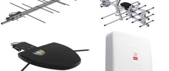
I needed a couple of antennas for digital, in places with “not the best reception”... I went shopping (this was before self-isolation - if it’s relatively budget-friendly, then it’s complete G. The more expensive one looks decent, but how it works is questionable.
I decided to make something homemade. It was somehow awkward to “twist” an antenna from a piece of cable (although rumor has it it works) - I wanted something simple, but more decent and advanced
In fact, the one I made is not radically more complicated, but somehow more “solid” or something. And the results of its testing were very encouraging, so I decided to sketch out a short description of what and how, in case someone else finds it useful 
... even if my street cats have a “normal” antenna on their house, what can you do without an antenna?!
The wire is not all finished yet, now we’ll assemble something!
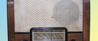
In the places described, I previously used home-made broadband log-periodic antennas, probably since the “beginning of perestroika.” They worked well in analog and not only on UHF, but “for some reason, digital was too tough for them.” I didn’t really delve into the essence of the reasons, I removed them and began to think about what to replace them with. Here is one of them, waiting for a place in the trash
A little history
In the early 60s of the last century, our compatriot Kharchenko K.P. developed a simple flat zigzag antenna with good characteristics.
Copyright certificate No. 138277 for an invention called “Band directional antenna” was issued to Konstantin Pavlovich Kharchenko in 1961 (according to his application dated June 16, 1960). In the same year, materials were published in the magazine “Radio” for repetition by radio amateurs.
The antenna is not critical to materials and dimensions during manufacturing, has a simple good match with the reduction cable, and it successfully combines multiple elements of a common-mode antenna array with a single feed point.
Log-periodic
If the antenna does not always cope with an analog signal without adjustment, then it is ideal for receiving a digital television signal. It consists of a long rod to which halves of dipoles of different lengths are attached. The gaps between the vibrators and their length vary exponentially. Calculating an antenna is quite difficult. There are several methods presented on the Internet.
Log-periodic antenna
Features of a log periodic antenna:
- The central rod feeds the right and left vibrators separately. They must be in antiphase;
- The rod consists of two load-bearing members. Left-right vibrators take turns changing carriers. The first left is the upper carrier, the first right is the lower. The next row is the opposite;
- The number of vibrators is determined by the design of the antenna. The longest ones, located at the back, are equal in length to the length of a half-wave of the lower limit of the range;
- The coaxial cable is laid to the middle of the structure, passing inside one of the guides. At the exit from the nose, the central core must be connected to the second carrier. Such a line, consisting of two wires, will act as a balun transformer. There is another gasket option;
- For better matching, the line is short-circuited behind the longest vibrator (a distance of 1/8 of the wavelength of the lower limit of the range);
- The diameter of the tubes should be 10-15 mm for a decimeter wave.
- Thin cables will cause high attenuation, requiring a wire of at least 6mm in diameter. The cable is tied only from the inside, otherwise the quality of the antenna decreases.
Log-periodic antenna circuit
Theory and calculations
The described antenna, in theory, has a horizontal “figure-of-eight” radiation pattern and a relatively high gain, which can be further increased by using a reflector/reflector.
To obtain maximum gain on all channels, it is necessary to make an antenna approximately in the middle of the range between the multiplexes used.
Finding (for calculations) the frequencies of multiplexes used in your region is easy,
for example, a request like “dvb-t2 channel frequencies” + “Krasnodar”
I found something like this:
The middle, between “my” two multiplexes, is 700 MHz - we will calculate the antenna at this frequency.
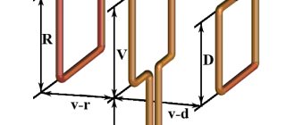
As a basis for calculating the dimensions of the antenna, we take the drawing of its author
Calculate the wavelength: λ = 300 / f [m]
300/700 = 0.428m, approximately 43cm length of each side of the rhombus
λ/4
=43/4= 10.75
The total length of the material we need (11cm*8=88cm) is less than a meter. The distance between the reduction contacts, where we will solder the cable, is 10-12mm (the standard value for this antenna for frequencies below 900 MHz).
I will make a simple antenna, without a reflector, however, to further increase the gain of this antenna, it is quite possible to install it behind it
for example, from a metal mesh/grill, foil material or simply a metal plate. Its dimensions should be approximately 20 percent larger than the dimensions of the antenna and it should be located at a distance of ƛmax/7. For my case: wavelength (channel 39) 300/618, it turns out...49/7= that is, about 7cm
For those who are too lazy to do the calculations themselves
— you can use an online calculator, the results will differ only slightly from those I received. Here, for example, this one - here you immediately enter the frequencies of two multiplexes and get the dimensions of the antenna (without a reflector) Or another option, with a reflector - I really want to note that in the second option a slightly different calculation option is used, different from the author’s. An antenna with angles other than 90° is assumed and the reflector distance is calculated as λ/8
To make the antenna sheet, it is recommended to use aluminum or copper (copper is easily soldered) with a diameter of 3 mm and higher - the larger the diameter, the more broadband the antenna is. You can use tubes; the thickness of the walls is not important, since only the surface of the material is used (in fact, you can wrap any dielectric with foil to obtain the required material). However, in my opinion, the easiest way is to buy a meter of large-gauge copper wire at an electrical supply store.
Advantages of the UHF range
The length of decimeter waves is 10 cm – 1 m, depending on the selected frequency.
Unlike meter waves, decimeter waves have a smaller area of propagation - within visibility. Shorter waves reflect better from obstacles in the path. Therefore, it is more rational to use them among multi-story buildings or industrial buildings - when reflected from their surfaces, they will cover more receivers.
Despite the fact that UHF is inferior to HF in wave propagation range, it is ahead of other popular frequency ranges, such as 2G/GSM, 3G/UTMS and 4G/LTE. One television transmitter in the range of 300-900 MHz is enough to cover large cities and small towns surrounding them.
Another advantage of UHF is noise immunity. Moreover, the narrower the operating frequency range, the less likely it is to jam the signal or overload the receiving antenna. Together with digital technology DVB-T2, decimeter waves convey to users only a good picture with sound.
With analog TV, we are accustomed to noise on the TV screen when the signal is poor. Due to the peculiarities of DVB-T2 technology - when receiving a digital signal, the quality is either excellent or there is no reception at all.
Antenna assembly
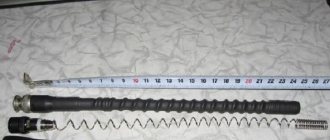
Let's remove the insulation from a piece of wire one meter long.
I got a wire with a diameter of 4.5mm
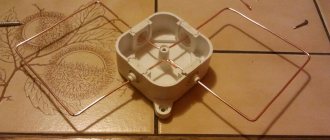
The tools you will need are a vice and a hammer. Measure approximately 11cm each and bend at an angle of 90°
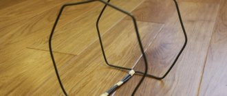
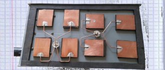
The end result is to get such a “geometric” figure
We cut off the excess and solder the ends. It should look something like this...
Solder the cable as shown in the photo.
We lay the cable along one side of the square and secure it with clamps. This arrangement of the cable is necessary for its coordination (there are different opinions, not everyone agrees with this statement).
When using a reflector, the antenna sheet at the extreme points of the squares can also be secured using metal stands, for example, soldered onto the remains of the same copper wire - there are points with zero potential (highlighted in green). In other places, fastening is allowed only through a dielectric.
Zigzag
Zigzag is a Kharchenko antenna circuit, refers to broadband devices. The design dimensions for the decimeter range are compact and easily allow it to be used indoors. It is especially effective in remote settlements when receiving in different directions. The limits of received frequencies while maintaining parameters overlap with a factor of 2.6-2.7.
Kharchenko antenna with reflector
The classic zigzag is difficult to manufacture and requires precise calculations. Widely used for receiving analogue television programs. For a digital signal, everything is greatly simplified.
Tests
And finally, a performance check and a rough
assessment of the quality of the resulting antenna.
In fact, everything is simple with the test - turn it on, it works! And to evaluate whether the game was “worth the candle,” let’s compare the parameters of the received signal from the manufactured antenna with the one I’m already using at the dacha, with a declared gain of 11dBi
The antenna is installed in the attic of a country house, at a distance of approximately 16 km from the tower.
Signal level: factory stationary antenna on the left / homemade on the right
At first glance, the difference is only 1% (95 versus 94) - but this is not a completely correct comparison, since my external antenna is connected through a splitter, which further weakens the signal.
The evolution of television broadcasting
A number of changes have occurred in broadcast television that must be taken into account before making a decimeter antenna with your own hands:
- Now almost all TV broadcasting is produced in the UHF range. One of the reasons is the economic factor. Equipment of transmitting stations: antennas, feeders are significantly reduced in price. The need for their preventive maintenance by highly qualified specialists is reduced;
- The TV signal covers all places that were previously inaccessible. In “blind corners” coverage is provided by a transmitter without maintenance personnel;
- Digital television signal has its own characteristic features. It feels little interference, but if the cable is mismatched, or there are phase distortions in any place in the receiving-transmitting path, the image may be “torn” even with a high signal quality;
- Television has a huge number of programs, and it makes no sense to configure the UHF antenna for several channels;
- Urban conditions for the transmission of waves have been transformed due to the rapid construction of multi-story buildings, the reinforced concrete buildings of which are capable of repeatedly reflecting them before gradually fading.
The length of the LW wave is in the range of 0.1-1 m. Hence its name. Electromagnetic waves can only propagate in the forward direction, without going around obstacles. Therefore, for long distances such communication is problematic. Its coverage radius is 100 km. The UHF antenna must be manufactured taking into account the changing requirements.
Assessing the performance of the antenna
Let's try to make a more correct comparison by connecting through the splitter input.
Well, in addition, for clarity, let’s add the number of participants List of antennas taking part in the comparison:
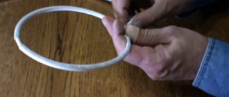
1. External antenna Funke BM 4551 external long-range,
declared gain, from some sources (bought at Yulmart), up to 16dB
2. There is an old UHF loop antenna, from TV Electronica 313d, I must say, despite its simplicity, it’s a very good antenna, that’s why it’s been preserved
3. I went to the store and bought for comparison in the review one of the cheapest, such as a symmetrical vibrator (100% the most purchased by pensioners, due to the low price).
I will carry out all “measurements” at one point, located as close as possible to the external antenna - its location was experimentally selected based on the maximum signal, so we can say that the conditions are approximately the same
So, we have already seen the signal level from the external antenna at 95% (at the time of current measurements it showed 94%), we take it as a standard. All comparisons are made by connecting antennas to the input on the splitter, to which an external antenna is usually connected.
Loop antenna, from Electronics 82% on 39 multiplex and 66% on 60
Budget with “horns” - 62%/38% (on the verge of losing the broadcast)
Double square - 92% on both multiplexes, about a couple of percent less than the external one
Out of curiosity, I decided to check the work of the reflector, which is easy to make from any metal mesh, plate or even foil... It REALLY works noticeably! The level rose to 96%!, which is even higher than the stationary one, with a declared gain of 11dB.
The most interesting thing is the object that I used as a reflector!
There was no foil in the house; the only thing available with a metal surface of the required size was... a laptop cover (I have a metal case). But the main thing is the result! It’s clear that I’m not going to “tie” the laptop to the antenna, and its amplification is enough for me without a reflector
Homemade option
Using scrap materials, it’s quite possible to create an indoor antenna - UHF antenna T2. For example, from two computer floppy disks, if you remove the actual magnetic surfaces of the disks from the envelope, you can easily get a Cheburashka antenna - a kind of big-eyed creature, if you have a little imagination.
Cheburashka antenna (drawing) Cheburashka antenna
An external version of the Cheburashka is also possible, then it is worth thinking about a more durable fastening of all parts and cable.
Outdoor antenna
Outdoor antenna
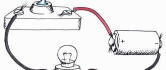
In addition to floppy disks, you also need a stick-stand, a piece of cable and a few nails or screws.
Similar articles:
- Making a projector using a mobile phone
- What is Nikola Tesla's coil or transformer?
- How to make a switching power supply?
Conclusion:
I can confidently recommend repeating it!
Simple, “cheap and tasty”... One of the simplest, indoor antenna mounts... with ordinary suction cups - if you’re lucky with the direction to the television center
The next antenna "recommended for repetition" is... log periodic
“Crazy hands” were with you. Good luck and good mood to everyone! ☕
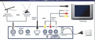
Satellite
Remember? We're talking about T2 terrestrial digital television, so forget about satellites. You will not receive terrestrial television in the DVB-T2 standard through a satellite tuner. You will not connect the T2 tuner to a satellite dish. We receive the T2 signal from the nearest broadcast tower in the UHF range. To a regular over-the-air antenna for a summer residence, not a “dish”.