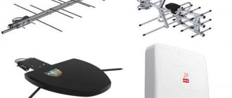
Circuits and radio electronics: MANUFACTURING FM ANTENNA FOR A TRANSMITTER, Radio transmitter circuits - read on the Radio Circuits portal
Reading time: 24 min Category:
- Connecting an FM antenna
- How to do it yourself?
- Useful tips
- Homemade antenna
- Connection and configuration rules
- Recommendations
- Homemade options for DVB-T2 reception
- What function does it serve?
- How to choose an amplification module
- Antenna connection
- Assembly instructions
- Installation of a radio signal catcher
- DIY technique
- Reasons for poor reception of radio stations
Connecting an FM antenna
It is believed that we connect an FM antenna using three methods:
- In direct case, the design is an integral part of the device. Used by cell phones. Often in transmitting devices the antenna is made of a quarter-wave dipole, the body of the device serves as the ground. The active resistance is 30 Ohms, the reactive resistance is reduced by restructuring the resonant circuit. The antenna is asymmetrical; the equivalent current flows into the ground as it goes to the cascade. It creates losses, plus the alignment creates interference. In the case of stationary devices, good grounding helps; if the length of the bare wire is comparable to a tenth of a wave, the ground loop will begin to radiate, generating additional interference.
- In the case of non-resonant power supply, a conventional feeder is used, the characteristic impedance of which is equal to the characteristic impedance of the antenna. Ensures no losses and maximum signal level. There is a traveling wave in the line, the length of the feeder does not matter, and linear losses are significant. A meter of cable to the first amplifier stage reduces the sensitivity of the receiver. Avoid stacking coils on the floor. The excess cable between the receiver and the FM antenna is cut off. The problem of a long feeder is cut off by an active amplifier. We'll have to run the 12 volt cable to the roof, we'll stop worrying about the length. Solutions are appropriate where there is nothing else to do but listen to the radio. There is no Internet, television, or other communications. While most store-bought products are set to 50 ohms, homemade ones need to be properly matched. This is done using an SWR meter; a special screw for performing the operation has been found on automotive structures. Will significantly improve reception. Moreover, the antenna parameters and length change. Ideally, the SWR is equal to one, in practice it is allowed below 2.
- The resonant antenna power communication lines are the most curious phenomenon. There is only one problem: the signal transmission conditions strongly depend on the wavelength. The feeder must be a multiple of half. A radio station broadcasts in a certain spectrum, the frequency to which the receiver and FM antenna are tuned is the carrier. There are harmonics swarming around, which are actually useful. A carrier devoid of usefulness is of no value. For television, resonant communication lines lose their meaning; frequencies can differ threefold. It is impossible to maintain the conditions of a multiple of half the wavelength. The beauty is that the wave impedance of the line ceases to play a role. The antenna will be matched in such conditions. A curious feature is vigorously used to measure resistances. For example, using a line 5λ long, an antenna is examined to exclude errors and interference. To measure antenna resistance, the characteristics of the feeder do not play any role, as mentioned above. However, a number of practical amateur radio antennas are used at the resonant frequency, the harmonic frequency. Power supply using a resonant line will be a good way out. All that remains is to match the receiver input with the resistance of the FM antenna.
The importance of alignment is clear to readers. It is not enough to implement the FM antenna device; it is recommended to carry out coordination
Otherwise, those who are impatient can borrow a method from Wi-Fi: take a piece of a quarter-wavelength feeder (solid wire), peel it off the screen, solder it onto a connector, and plug it into the receiver so that the cable is positioned vertically. A primitive FM antenna, according to experienced people, performs well in the presence of waves on the air, therefore, it is suitable for impatient readers who do not want to coordinate the project. The simplest FM antenna, made with your own hands from any piece of coaxial cable, is capable of receiving. Feel free to take a television, the power will be lost.
We hope that we have given readers an understanding of the basic principles of designing FM antennas. By the way, don’t throw away broken gadgets. MP3 players, phones, and modems often contain what you need. Even a tiny factory FM antenna can give a homemade design a hundred points head start. Remove the required part and examine the electronics. It will come in handy. The time is not far off - we will program home controllers, create your own digital information processing devices.
Half-wave antenna frequency 145 MHz
The quarter-wave homemade VHF antennas discussed above are not the only way out of the situation. The advantage is low wave impedance; half-wave options have the right to exist. A piece of wire with a diameter of 1 mm and a length of 103 cm has a resistance of 1 kOhm, 20 times higher than a standard coaxial (50 Ohm).
To reconcile the difference in values, a U-shaped contour is used. The future wire antenna should be cut several centimeters shorter/longer than 103 cm. It will slightly increase losses due to an increase in the reactive component of the impedance, significantly reducing the real part of the impedance, and the matching device will be easier to configure.
The filter inductance is connected in series with the antenna and is formed by 5 turns of wire with a diameter of 1 mm, wound in increments of 2 mm on a mandrel with a diameter of 6 mm. Trimmer capacitors KPVM-1 (5-14 pF) are connected with one plate to the ground on both sides of the coil.
The antenna for the VHF radio is adjusted by measuring the SWR and field strength. The minimum of the first parameter coincides with the maximum of the second. Otherwise, the length of the antenna is shortened and measurements are taken again. It is recommended to initially select a wire length of 102 cm, gradually cut it from the upper end, selecting the optimal value.
How to do it yourself?
You will need it.
- Soldering iron, solder and rosin, soldering flux. Instead of the latter, zinc chloride was previously used - it is prepared from tablets containing hydrochloric acid. These tablets are used by stomach patients. The source of zinc is any alkaline (salt) battery that has exhausted its service life: its “glass” is made of zinc.
- Copper wire is a thick winding wire. An alternative is to twist all sorts of thinner stranded wires. For strength and reliability, they are soldered with solder so that the copper does not oxidize and the conductor does not “unravel.”
- Dielectric base. It can be any board, plywood, chipboard, fiberboard, as well as homemade or industrial getinax (or fiberglass), from which the printed tracks have been removed. You can also use flat pieces of plastic from old, outdated electrical appliances.
- Fasteners Bolts, screws, self-tapping screws, lock washers, nuts. Stock up on the right amount of them. Perhaps plastic “mounts” will also come in handy.
- Coaxial cable (with a characteristic impedance of 50 or 75 ohms), plug (for the antenna jack of your receiving device).
- The simplest locksmith tools. This can be a flat and figured screwdriver, pliers, side cutters, hacksaws for metal and wood, possibly an adjustable wrench and a hammer. An angle grinder and a drill will also speed up the antenna manufacturing process.
- Waterproof varnish or paint. The conductors and the place where the cable is connected to them must be painted. This will protect them from corrosion caused by drops of water.
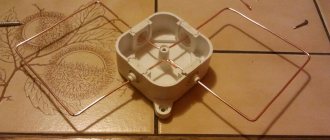
If you are not a radio specialist, then take a ready-made drawing. An example is a loop antenna. To make it, do the following.
- Based on the dimensions from the drawing, bend a working element – a “butterfly” – from copper wire.
- Place it on a strong dielectric base, tying it to a wooden or plastic plate using “mounts”. A more “advanced” option is vertical stands on the edges and on a screw fastening. This is what “homemade workers” did in the 1990s, making antennas for receiving UHF television channels.
- Solder the cable. The central core is connected to one side of the antenna, the braid to the other. There should be a gap of up to 1 cm between the parts of the figure eight and them. The dipole antenna is connected to the cable in the same way.
- Paint the entire structure.
- After the paint has dried, secure the structure to a pole or pipe. Tie the cable in several places to the support.
- Attach the plug to the other end of the cable and raise the antenna higher. Point it at the broadcast city. If the distance is too great, there is no direct signal - they find a reflected one, for example, from a mountain or the tallest building not far from you.
The antenna is checked based on the reception quality of the desired radio station. Radio transmitters today are located in random cities and regional centers - many private radio broadcasters have appeared, making money from advertising. Radio stations are not located in the location of the city television tower (on the “telecenter” hill), but on a low mast about 30 m high. Not everyone wants to rent the “strategic height” of a city or region, broadcasting from the roof of a 9 ... 25-story building through a low-power (up to 100 W) FM transmitter.
There should be as little noise as possible in the background of the radio transmission. Radio reception must be in stereo format. It is impossible to receive a stereo transmission when the signal is weak - noticeable noise appears in its background. Rotate the antenna until you get the best quality. If the station is too far away and the noise remains, connect the radio amplifier to the cable break, next to the antenna.
A universal cable will help here, in which, in addition to the “coaxial”, a pair of additional wires are hidden under the outer protective sheath. The power line is isolated from the central conductor by the braid of the main radio cable. If there is no such cable, the amplifier’s power is supplied through wires to the radio receiver nearby, separately.
You can find out how to make an FM antenna with your own hands in 15 minutes below.
The antenna for the music center allows you to receive signals from popular radio stations, listen to songs and favorite programs. In some cases, the built-in amplifier is not enough: the sound comes through with interference or disappears altogether. In this case, industrial or home-made devices for receiving signals will come to the rescue. Homemade antennas can be made quite easily and quickly from scrap materials.
VHF antenna triple vibrator
The parallel feeder is connected to the halves of the middle wire broken in the center. The dimensions and structure of such an antenna are shown in Fig. 3. The radio communication range on VHF can be significantly increased without increasing the transmitter power by using an antenna pin; 2 - Insulating sleeve; 3 - copper or aluminum tube; 4- feeder; 5 - insulators; 6 - mast. Length of pin and tube 71 250/f; tube diameter 30-40 mm
If a second wire is placed parallel to the half-wave dipole at a distance of about a quarter of a wave, it will change the directivity characteristic of the antenna. Such a wire (called passive, since it is not connected to anything), slightly longer than the dipole, is placed behind the working dipole and acts as a reflector, amplifying the radiation in the opposite direction.
A passive radiator shorter than the dipole, placed about a quarter wavelength in front of it, amplifies the radiation in that direction. Such a wire is called a director.
Rice. 3. VHF antenna - triple vibrator.
Useful tips
It is important to choose the right location for installing the antenna. A car body can be both a kind of indicator of improved signal reception quality and an interference
The best place for mounting is the center of the roof. There should be no foreign metal objects near the catcher. It is better to purchase combined antennas for receiving various communication signals ready-made.
The installation must be protected as much as possible from the influence of the external environment so that contacts do not oxidize and parts of the entire structure do not rust.
An antenna made by yourself is an effective way to save money, improve the quality of signal reception, and allow you to technically modify the radio in your own car.
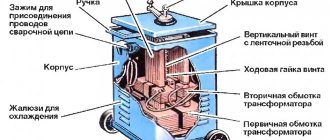
Transformer
The antenna, equipped with a reflector and director, has a pronounced one-way directionality. At the same time, its efficiency increases, since energy is emitted or received in one main direction and directions close to it.
When the distances between the emitters are less than a quarter wavelength, simultaneously with an increase in directivity, the radiation resistance of the dipole decreases. A feeder with a resistance of 70 ohms then turns out to be unsuitable for direct connection to a dipole due to the large difference in resistance and the resulting mismatch.
Mismatch leads to the formation of standing waves in the feeder and to an increase in its radiation, which creates large energy losses. Dipole matching in a directional antenna with a two-wire feeder can be achieved by using a transformer between the antenna and feeder. The structure of such a transformer is shown in Fig. 4.
In addition, matching can be obtained by using a loop dipole instead of the usual one. When a loop dipole operates in a complex antenna, its radiation resistance is reduced, and power can be supplied directly by a feeder from a coaxial cable with a resistance of 70 ohms.
The dimensions of the antenna in this case are as follows: length of the loop dipole l = 142,500/f (hereinafter l - in mm and f - in MHz); the length of the reflector is 5% longer than the length of the working dipole; the length of the director is 4% less than the length of the working dipole; distance from the reflector to the dipole l = 45,000/f. The distance from the director to the dipole is l = 30,000/f.
Rice. 4. Transformer device for matching the working dipole with a 600 ohm feeder. 1 - dipole; 2 - coaxial cable 70 ohm; 3 - feeder made of parallel wires with spacers.
Homemade antenna
Anyone can do it; for this we need a few simple tools that are available in every home:
- A piece of copper wire.
- An ordinary kitchen knife.
- Pliers.
Note that not in all regions of our country the FM signal stably covers the entire territory. In some remote locations, the conventional built-in antenna of a music center is not enough. In this case, device owners begin to try to strengthen the signal on their own. Most often you can see a standard FM antenna wrapped in wire. In other cases, this wire is placed outside the window (for example, through an open window), in the hope that it will somehow strengthen the signal. Indeed, such practice often helps, and the radio still manages to be picked up.
So, let's take a closer look at how to make such a standard antenna amplifier with your own hands. This is done in stages:
- Take a piece of copper wire.
- Measure the length you need and cut using pliers or wire cutters.
- Now strip the cut piece of wire using a regular knife.
- Next, you should securely tape the cleaned wire to the existing antenna and try to catch the signal.
If significant improvements have not occurred, then you should pay attention to the back of the music center. In the area where the plug sockets are located there is often a so-called input for additional antennas
Some manage to amplify the signal by inserting a wire into this socket, but it is worth noting that such a practice can lead to unstable operation of the device as a whole, and sometimes to breakdowns. Moreover, the effectiveness of this method seems very doubtful.
If amplification with a wire-type device does not help, you can try to assemble a rod antenna. It is highly directional and more resistant to urban interference. Most often, it is made from an existing old television antenna, taking into account the fact that some television broadcasting frequencies have shifted or even switched to online or satellite broadcasting.
In order to make it yourself, you need:
- Secure the load-bearing structure to the outside of the building.
- Plug the wire into the corresponding socket of the music center (to make it you will need a plug for the corresponding socket and the ability to work with a soldering iron).
- Search for radio stations.
Of course, there are options for homemade antennas with a more complex manufacturing algorithm, but their assembly will require much more skills and time. Wire and whip antennas are the simplest options available to any user when it is necessary to improve the signal using improvised means.
Voice radio in the country: ways to strengthen the signal
In a suburban area, receiving radio broadcasts and music is good entertainment, including during gardening work. Unfortunately, in practice, many are faced with the fact that the receiver produces a large amount of interference. Sometimes the signal is completely lost, and it is simply impossible to find your favorite radio station by setting the slider to the desired wavelength range. All this indicates poor reception, which can be improved in simple ways.
Build up your antenna
No matter how you receive a radio signal, it requires an antenna. If we are talking about a receiver with a folding pin that is hidden in the case, then its size is often not enough, especially if we are talking about a place far from the city, where the reliable reception zone disappears. In this case, you need to make the antenna longer and raise it higher. In a private house, this is done very simply - a pole is fixed on the roof with a piece of wire, stripped of insulation, tied to it. The material for receiving the signal is not important - it can be either copper or steel.
Make a reverb
The simplest device that amplifies a radio signal is nothing complicated. It should be made in the form of a frame, usually triangular or square, made of three meters of copper wire stripped of insulation. In some cases, it can provide stable reception at a distance of 150 km from the city. One end is connected to ground, the other to the central output of the antenna socket.
Connect amplifier
This device is usually a box that is connected to the antenna frame. Inside the case there is an amplifier chip with active power supply. In order for the circuit to work, you need to plug in an adapter that produces 12 V DC. A cable comes from the amplifier, which connects to the FV receiver. This method is most widely used for receiving television signals, but where television broadcasts are received, the radio will be heard just fine.
The listed methods do not exhaust the possible recipes for amplifying a radio signal under various conditions. Radio amateurs on forums willingly share their inventions, and not all of them are difficult to manufacture.
Connection and configuration rules
The design of a radio for a car involves connecting 3 wires. The first is required for grounding and installation of the receiver. It is connected to a metal fastener and then tightened. The second is for food. It is connected to a wire extending from the receiver.
The third is necessary to establish contact. Connects to a special connector in the radio. Sometimes combined with a power cord. Wires are laid only when the installation is completed.
The antenna must not be mounted next to other metal elements.
If the device is installed outdoors, it must be protected from adverse environmental conditions. If this is not done, the metal may oxidize due to rain or snow, which will lead to malfunctions of the device.
The principle of operation of radio receivers
Stable operation of such a device is only possible if an optimal signal level is created at the input, exceeding the required threshold. Experts call this parameter the sensitivity of the unit. Only if the received signal is above this threshold will the radio work well, and the user himself will be able to enjoy high-quality sound of his favorite music. Otherwise, there may be no reception at all.
Such consequences most often arise not only due to the great distance from radio stations, but also in a metropolis. Various types of interference are found in those receivers that operate in the FM and VHF bands. The thing is that these types of signals are distributed in a special way. Their frequency does not exceed 108 MHz. Experts note the fact that all waves from this band propagate only within the line of sight and very poorly bend around any hills in their path.
Recommendations
If we talk about recommendations for the creation and use of such antennas, then first of all we should note several.
- There should not be any metallic foreign objects near such a device. Otherwise, they may interfere with the reception of the signal or reflect it, which will also negatively affect the quality of its reception.
- Care should be taken to protect the antenna from exposure to natural factors. Otherwise, its parts may rust and sooner or later the device will simply fail.
- In most cases, it is necessary to make drawings before starting work, where you need to describe in detail the dimensions and dimensions of the device, its type, as well as the algorithm of actions for its creation. This will make it possible to quickly and accurately implement one or another idea and obtain a high-quality antenna for receiving a stable FM signal.
How to make a radio antenna with your own hands in 15 minutes, see below.
More complex radio
If you want a slightly more complex radio, use a metal file and two pieces of wire. Connect the handle of the file to one terminal of the 9-volt battery, then connect a second piece of wire to the second terminal and run the design by swiping up and down the file. If you do this in the dark, you will be able to see very small 9 volt sparks running along the file as the tip of the wire makes the connection and disconnection. Keep the file near an AM radio and you'll hear a lot of static.
In the early days, radio transmitters were called spark coils, and in addition they produced a continuous stream of sparks at much higher voltages (e.g. 20,000 volts). The high voltage consequently contributed to the creation of large sparks, such as you see in a spark plug, for example. Today a transmitter like this is illegal because it spams the entire radio frequency spectrum, but in the early days it worked great and was very common because there weren't many people using radio waves.
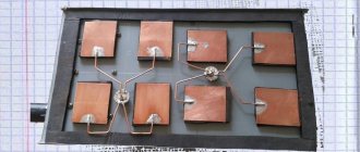
Homemade options for DVB-T2 reception
First of all, let's decide what exactly we are catching.
In Russia, after the introduction of federal digital broadcasting throughout the entire territory (with the exception of some areas where it turned out to be cheaper to allow all residents to use satellite broadcasting for free), two multiplexes should be received - a set of 20 channels included in the state package. Access to them is free, they are transmitted, although digitally, but openly on the decimeter range.
Therefore, it is necessary to assemble a television antenna designed to receive the UHF range.
Is a homemade antenna difficult?
Difficult! Easy!
There are many design options suitable for receiving a DVB-T2 television signal: the UHF range and the conditions for its reception have been thoroughly studied by generations of physicists and radio amateurs.
Here is a comparative table of characteristics of the simplest and most effective homemade products used for receiving digital television:
| Antenna type | Gain, dB | Max. reception range without amplifier, km | Max. reception range with amplifier, km | Received range, MHz |
| 0–3 | 15 | 15 | 440–800 | |
| 3–5 | 15 | 40 | 470–622 | |
| 5–11 | 20 | 70 | Any (by calculation) | |
| 9 | 15 | 60 | Any (by calculation) | |
| 5–6 | 10 | 50 | Any (by calculation) | |
| 8–12 | 30 | 100 | Any (by calculation) |
Of course, this is not a complete list of what you can do with your own hands. However, the schemes of such designs as the Kovachev, Turkin and “wave channel” antennas have significant disadvantages:
- too complex, and the efficiency is not so high that it makes sense for an untrained person to try to make them;
- long-range, but narrowband. For example, if both multiplexes are separated by 6 or more channels (which is regularly found with repeaters in rural areas), you will have to make and configure two antennas of the Turkin design, one for each multiplex, and then select a matching transformer and level it (ideally to the nearest millimeter) cable length.
Next, we will consider each option separately, highlighting the main pros and cons.
Causes of signal attenuation
Each receiver is necessarily equipped with an antenna, which helps the device perceive the signal, separating it from interference and noise. A high-quality unit has good sensitivity to broadcast waves, but as the distance increases, the radio signal level decreases. At long distances, signal reception becomes simply impossible.
Even in advanced cities, there are often dead zones where the receiver does not work. The whole point is that the broadcast signal travels in a straight line , but it cannot pass through obstacles (multi-story buildings). In such a situation, the signal is reflected and loses its power.
Experts say that the linear propagation of FM radio waves does not allow devices to pick them up normally and beyond the horizon, where the broadcast of waves from a previous radio station simply cannot reach. The signal gets there only after reflection from the clouds, and this largely depends on weather conditions. You can get out of this situation only by independently manufacturing more powerful antennas.
What function does it serve?
The only function of an external (additional) antenna is to increase the reception range in areas of very weak radio communication. This is how long-range and ultra-long-range techniques are implemented. Car antennas are in great demand among truckers who need high-quality communications and reception over many tens of kilometers. Radio stores often sell antennas with a very short pin - only 10-25 cm. A non-professional, who does not particularly understand radio as such, takes what they give - he does not realize that if the pin is increased to the required length, the reception quality will noticeably improve .
A tribute to the fashion for miniaturization and lightness of any devices takes over - as a result, the quality is far from expected.
Radio Basics: Parts
As you may have noticed from the previous section, creating static is incredibly easy. However, all radio stations today use continuous sine waves to transmit information (audio, video, various data). The reason we use continuous sine waves today is because there are many different people and devices that want to use radio waves at the same time. If you had any way of seeing them, you would find that there are literally thousands of different radio waves (in the form of sine waves) around you right now - TV broadcasts, AM and FM radio broadcasts, police and fire radios, satellite TV broadcasts, cell phone conversations, GPS signals and so on. It's also amazing how many uses there are for radio waves today. Each different radio signal uses a different sine wave frequency, and that is how they are all separated.
Any radio installation has two parts: a transmitter (transmitter) and a receiver (receiver). The transmitter intercepts some kind of message (this could be the sound of someone's voice, the image of a TV screen, data for a radio modem, or any other thing), encodes it into a sine wave and transmits it with radio waves. The receiver, of course, receives radio waves and decrypts the message from the sine wave that it receives. Both the transmitter and receiver use antennas to radiate and capture the radio signal.
How to choose an amplification module
The first criterion by which an FM signal amplifier for a car radio is selected is its power supply type. There are two types of devices on the market today.
- With external power supply. Such an amplifier has a tap, one wire for connecting to the vehicle’s on-board network.
- Powered by antenna cable. Such devices connect only to a certain class of radio tape recorders. The latter must have the option of power supply via an antenna cable.
Regardless of the technical solution, connecting the antenna amplifier to the car radio is not difficult. However, the main thing is to buy a device with the right characteristics. The criteria for choosing the optimal model are as follows.
- The frequency band is selected depending on the type of radio and the radio tuner installed in it. If this is an old cassette model that receives short, medium and fm waves, a wideband amplifier will be required. For modern radio tape recorders, a narrowband model operating only in the FM range is sufficient.
- Type of antenna to be connected. For conventional pin models, a conventional amplifier is used. When using directional (also called dipole) antennas on a car, a more complex device will be required. The circuit solution includes a matching module.
- The gain should be between 10 and 30 dB. Today you can buy models with a higher indicator. However, it is not recommended to do this in a large number of cases.
It is worth talking in more detail about choosing the optimal gain. It is determined not only by the desired reception range. The fact is that the maximum power of the car radio amplifier determines the final signal level at the device input. However, there is a technical limit to its increase.
If the installed antenna amplification module is very powerful, and the car is located in an area of reliable reception, in a large city, the radio will simply stop receiving the radio. The protection system will work. The amplification device, generating an excessively strong signal, will take its value beyond the technical limit. As a result, in order to protect the primary reception circuits, roughly speaking, the antenna input will be blocked.
When the actual use of the car involves both its movement in the city and travel far beyond its borders, it is recommended to install an amplifier blocker. This is a circuit that turns it off if necessary, making a bypass to the main cable channel of the antenna. You can buy an amplifier that turns itself off when a certain limit signal is reached at the output.
What to choose
Today, the manufacturer offers not just one, but a whole host of amplifier options for a car antenna.
Domestic manufacturer
Amplifier Triad
It is interesting that our domestic manufacturer also offers a whole line of products called Triad. All models deserve praise, and especially the amplifier for the car radio antenna Triada-304 Dalnoboi, which is equipped with the function of turning off the device and operating in the FM/AM/VHF radio bands.
Foreign manufacturer
Amplifier from Prologi
Among foreign manufacturers, Prologi products take pride of place. For example, their model TFB-100 is capable of amplifying digital and analogue signals and simultaneously working with two antennas.
On your own
Yes, there is such an option. For radio amateurs, it offers special kits from which you can assemble a full-fledged amplifier with your own hands. Again, homemade amplifiers are assembled using a two-stage circuit. Well, now you have learned how to strengthen the radio signal in your car radio. Installing an amplifier purchased or made by yourself will not take much time and effort. All you have to do is follow the instructions, watch the video review and study useful photo materials. The price of amplifiers varies and it all depends on the reception range, as well as the manufacturer.
Antenna connection
Even a properly designed and well-made antenna will perform poorly if there are errors in the connection.
The following conditions must be met:
- Use shielded cable.
- Securely solder contacts and connectors.
- Make sure that the core and screen are tightly connected to the radio input group.
- Ground the antenna.
- If there is interference when powering the radio from the network, when there is no ground wire in the socket, it is better to connect the radio or transistor to ground. For this purpose, most devices have a special socket or terminal.
If the reception quality is not satisfactory, and changing the location and direction of the antenna does not help, you will have to install an amplifier.
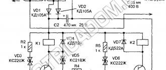
A simple and low-cost circuit of such a device is assembled, for example, on an RFMD SPF5043Z microcircuit. The advantage of the design is that the board can be made without chemicals on a 2-sided PCB measuring 15-20 mm and placed in a shielded case.
Operating principle in receive and transmit modes
The first antenna is a Hertzian symmetrical vibrator. In fact, the device is practically not used.
The shape and design of a device, be it an antenna for television or a radio telescope for studying the universe, depends on the purpose and wavelength that is realized for this device. Metal horns and conductor sections/systems are widely used.
Waveguides have also found application:
- made of metal;
- from dielectric;
- with slots cut into the metal walls.
To improve the radiation pattern, lenses and reflectors are used, which are installed on the emitters.
Structurally, the antenna is a system of conductors connected directly or through a special path - a power line, to a transmitting or receiving device.
The radiation system includes:
- generator/oscillation source;
- feeder (“feeding/supplying” from the word “feed” - to feed/supply) tract;
- emitter, i.e. transmitting antenna.
During transmission, a source, which can be a radio transmitter, creates an alternating electric current flowing through the antenna conductors. According to Ampere's law, a magnetic field is generated around current-carrying elements, changing over time. It, in turn, not only affects the current passing through the conductors, but also creates, according to Faraday’s law, an alternating vortex electric field, which reproduces the magnetic field, etc. This produces electromagnetic waves emitted into space by the antenna.
Reception system:
- receiving antenna;
- feeder;
- receiver.
The receiving antenna works like this. Electromagnetic field waves fall on the conductors of the device, inducing currents into them. Through the feeder, these induced currents enter the input impedance (complex resistance between two circuit nodes / poles of a two-terminal network) of the receiver, generating a voltage.
Assembly instructions
You can make both inactive and active (with an amplifier) devices with your own hands. The production technology consists of several stages:
- preparing the necessary tools;
- direct assembly;
- fastenings to the machine body;
- connections.
Assembling different types of antennas for a radio with your own hands differs significantly even in the selection of necessary tools.
Production of an inactive installation
Passive antennas without an amplifier are considered quite simple in design. To create such a device, you will need:
- copper wire (diameter from 1.5-2 mm);
- high quality nut;
- good file;
- screwdriver;
- thermal glue (can be replaced with heat shrink tube);
- screw (diameter M5);
- lock-nut.
Assembly is carried out in stages. For this:
- Take copper wire and twist it to a length suitable for a particular car.
- The resulting spiral is placed on an M5 screw, secured with a nut and a lock nut of the same size (soldered on top). The structure is treated with thermal glue, or wrapped using heat shrink tubing.
- The surface is sanded with a file. This procedure is done provided that the spiral has been treated with glue (only after the substance has completely dried).
- Install a homemade antenna. The spiral blank is inserted into the hole made (at the base), and the wires are connected.
To give the installation an aesthetic appearance, a film is glued onto it, treated with a primer, and painted. The passive device is ready.
Creating an active fixture view
A special feature of this technique is the presence of equipment that enhances signal reception. When creating internal active installations, frame structures are used. This requires the following tools:
- copper wire, always with insulation (diameter - 2 mm);
- home amplifier (a television device will do);
- high-quality soldering iron;
- a connector that is suitable for a radio;
- good nippers;
- glue.
An amplifier housing designed for a regular home antenna is often used as the basic basis for the device. Solder a wire to it, which, in turn, will connect to the radio. This is necessary for the amplifier to receive and transmit signals.
The antenna plug is connected to the socket, and a connector is mounted at the other end of the wire. The power cable for the amplifier in car radios is considered the control cable; it is painted blue.
An active type receiver is mounted on the roof of the car so that signals are well received. To do this, two holes are drilled in the housing - mounting and auxiliary. The antenna wire is laid around the perimeter of the driver's door, fixed with glue. After installation on the roof of the car, attach the (side) cable to the rack and carefully connect it to the car radio.
Installation and connection features
Traditionally, active types of antennas for radios are installed on windshields in the upper right corners or behind rear-view mirrors. Passive installations for receiving signals are placed on car bodies, usually mounted on roofs.
Any antenna should be mounted only on a clean surface. For installation, use glue or masking tape, bolts, nuts, lock nuts for grounding, and a drill suitable for the diameter of the antenna wire. The mounting area must be degreased with a special cleaner.
Fix the devices with glue or masking tape. After installation, wires are laid from the antenna to the radio. This is done either around the perimeter of car doors or windows, or directly around the interior through special openings.
The design of an ordinary car antenna has three wires:
- The first is used to ground the device. It attaches to a metal mount on the body. Secure the wire with a bolt, a strong nut and a lock nut.
- The second is used to power the device. It is connected to the wire coming from the radio.
- The third is a contact one; it is connected to a specially designed connector.
Most often, the second wire is combined with the third; by connecting the power, the contact function is activated, and the antenna begins to receive the signal.
Step-by-step installation instructions on the roof
If the supplied cable is not long enough, an additional one will be required. The cable must be braided and have a resistance of 75 ohms.
- At the installation site, it is necessary to drill two holes: one with a diameter for mounting the antenna and one with a diameter of 5 mm for an auxiliary one.
- The metal at the installation site is cleaned from the inside of the cabin.
- To avoid corrosion, the installation site is treated with mastic on the inside of the cabin and sealants on the outside.
- For installation, it is necessary to make an insulator (spacer) from copper and fluoroplastic washers to which the cable is soldered.
- The junction of the insulator and the cable must be sealed.
- We install the antenna on the roof and tighten the insulator nut from the inside of the cabin.
- We lay the cable from the antenna to the radio under the car trim.
- We connect the antenna to the radio and check the signal quality. Watch the video on installing the antenna
Sometimes standard antennas installed on cars have low sensitivity, or over time, as a result of mechanical or other damage, they stop working completely. At first, of course, every driver thinks that he doesn’t need this antenna, they say, I’ll listen to CDs, not the radio. But over time, the downloaded music begins to get boring and you want to listen to the banal chatter of DJs on the radio. That’s when the need to purchase an active car antenna arises.
Installation of a radio signal catcher
Installation of an outdoor horizontal antenna begins with the selection of supporting structures. You will subsequently attach insulators to them with your own hands. One of the supports must be installed on the roof of the house. It needs to be reinforced with guy wires. A tree of suitable height can be used as a second support. Insulators can be installed on construction sites using steel cables.
You must attach the outer part of the FM antenna to the insulators with your own hands. It does not need to be subjected to great tension. The wire shrinks if the air temperature is low enough and may lose integrity at low temperatures. Roller blocks will eliminate unnecessary vibrations. To use them, place a small weight on the other end of the wire. It will be connected to the FM antenna if you throw it through the insulator and block.
The receiving part of the antenna must consist of one piece of homogeneous material. If you do not have a homogeneous wire, it is better to construct an FM antenna from separate identical elements. They need to be cleaned and soldered with tin. Equipment for vertical descent of the antenna does not present serious difficulties
Please note that the wire should not be connected to foreign elements. You need to fix the antenna wire with your own hands on a special pull-out stand
This will prevent it from being in the wrong position in windy weather.
If the space for installing an FM antenna with your own hands is limited, you need to use a different design. These are several pieces of wire that look like a “broom”. They will be securely connected by a cable at their lower ends. The ends of the wires can be tightly filled with molten tin. You must cover the soldering area with reliable insulation in the form of bitumen or similar material.
A DIY indoor antenna will be the best option to replace an external catcher. Insulators must be fixed indoors. Their location closer to the ceiling will give an advantage in the quality of signal reception. The wire should be stretched horizontally or rolled into a spiral.
How to make a frame structure?
An aluminum hoop with a diameter of 77 cm and an internal diameter of 1.7 cm can be found in almost any sports store. Plumbing pipes made of a combined metal and plastic structure are well processed. A copper tube with a slightly smaller diameter (16 mm) is also suitable for a radio.
Antenna Rakhmattulaeva
The design of the radio antenna is quite simple.
- The central core, braid and a short piece of coaxial cable must be soldered to the contacts of the variable capacitor.
- The other end, the central core and braid, must be soldered to an aluminum hoop. You can also use car clamps, which need to be thoroughly cleaned, with a diameter of 16-26 mm. The contact area also needs to be thoroughly cleaned.
- The ratio of the frame circumference to the communication loop circumference should be 1:5.
- From the end of the coaxial cable, as well as from the central core, you need to remove the outer insulation to a length of 1 cm with your own hands.
- From the middle of the cable for the FM antenna, you need to measure half a centimeter in both directions and remove the outer insulation. After this, the cable braid must be removed. This will lead to its rupture.
- Check the range of the transceiver device so that the frame has a resonance from 5 to 22 MHz. With other capacitor capacities, you can change the parameters of the transceiver device.
- If you are more interested in low frequency ranges, it is better to use a frame with a larger diameter - 1 or 1.5 meters. If high-frequency - 0.7 meters.
This solution is a simple option to obtain a resonant antenna capable of operating in many bands. Its radiation pattern will be the figure 8. Antennas made of aluminum and copper work approximately the same.
We have brought to your attention popular types of radio antennas that you can make yourself. Most of these solutions are simple enough to make at home, and their ease of setup will allow you to easily cope with the most complex problems.
Rating of the best models
The rating of car antennas includes models with the largest number of positive reviews.
Triad 55 Turbo
The Russian-made device picks up VHF and FM waves. The model is suitable for all types of car radios and is installed on the windshield. The radio antenna is capable of picking up signals at a distance of up to 150 km from the source. The kit includes an antenna adapter for the car radio and a filter that eliminates most city noise.
Installation of a car antenna is carried out using a fitting and a power cable. The large length of the wire allows for hidden installation without the use of extension cords.
Automania Digital TV/FM
The model is used not only for listening to radio stations, but also for watching TV. This is convenient for drivers of passenger transport making intercity trips. The device has an oval shape and 2 branches with spiral wire laying.
The device is equipped with a built-in amplifier that improves the quality of a weak signal. The antenna works well at low and high temperatures. The device is powered by a voltage of 12 V. The model is fixed to the windshield using adhesive tape.
Bosch AUTOFUN
A retractable car antenna will appeal to any driver who is used to listening to music while traveling. The German model is installed on the windshield; its minimal dimensions allow it not to block the view. The round-shaped case is equipped with an LED element that reflects the operating mode, and a plug through which a 12 V power cable is connected.
The block is equipped with 2 antennae that capture the signal. When installing the device, the metal rods are moved apart so that they form a right angle.
Phantom TV Impulse
A radio antenna picks up several types of signals, including digital ones. The triangular body is equipped with an LED element and the developer’s logo. All wires are located on one side. The antennae are distributed along the glass, which expands the operating range of the device.
The power cable is connected to the TV output. The latter is suitable for setting up all TV models. The power cable can be connected to the battery without adapters. Amplifier included.
Triad VA Euro 65
This is the simplest and cheapest model of outdoor antennas. The cone-shaped body has a single tendril located at an angle of 60°. The device can be placed on the roof. A hole is made in the top of the car where the antenna pin is inserted. Secure the device with a nut. The power cable is inserted into the groove under the casing. The range is 90 km.
The length of the outer part is 20 cm. The compact device is resistant to mechanical damage. When exposed to wind, the antenna quickly restores its previous position. A passive device only picks up radio signals.
Lemm Turbo AT-2001
A good telescopic antenna is made of stainless steel and silumin. The central part is expanded, which allows the installation of a rubber seal and fasteners. For fixation, a hole with a diameter of 4 mm is made in the body. The 2 m long rod allows you to configure the antenna to receive signals of any range.
The presence of a long rod also causes inconvenience. The rod clings to branches and crossbars. The device has increased power (up to 2000 W). A 4 meter installation cable is included. The heavy weight of the main unit requires reliable fixation. There is an adapter for magnetic mounting.
FM Calearo ANT 77 27 085
Italian developers have expanded the functionality of the standard model, adding the ability to receive GSM and television signals. Made of durable plastic, the body has the appearance of a shark fin. The device installed on the roof does not create inconvenience when driving under barriers and bridges.
The kit includes 2 long wires. The device can amplify both analog and digital signals. The model is available in 3 color options that will look good on all cars.
DIY technique
Making a radio antenna with your own hands is not that difficult, the main thing is to prepare all the necessary materials and follow the basic rules. A significant increase in the quality and sensitivity of reception is achieved by vertically installing the device under the radio wave propagation range. It takes a craftsman from 30 minutes to 3 hours to make one unit. But to create the structure itself you will need accessible items that can often be found in the garage.
Universal pipe unit
The basis of the design is presented in the form of heating or intra-house water pipes. The final product is extremely strong and durable. For work you need to prepare the following materials and tools:
- High-quality copper or brass foil.
- A special ferrite core taken from a tube TV or a line transformer.
- Durable installation wire up to two meters long and with a cross-section of 0.25 sq. mm.
- Regular PVA glue, as well as adhesive tape.
- To connect the antenna to the receiver itself, you will need fixing pins.
Initially, you need to take the core and make a winding for it. For these purposes, you can use not only electrical tape, but also paper, which must be laid in two even layers. One ball of foil is carefully wound over the paper with a slight overlap of the turn (1 cm). In the overlap area, everything should be isolated to prevent contact between the two sides of the winding. The master must wind 26 turns of wire with bends of 8, 12 and 24 turns onto the preparatory screen. The ends are inserted into the connecting pins. The final configuration of the receiver is carried out according to the scheme for selecting the windings of the communication circuit.
Varieties of the model range
Anyone who has decided to build an antenna for FM radio with their own hands must understand that the main task of such a device is to capture the broadcast signal, amplify it and transmit it to the input of the receiver being used. Depending on the required range, the final unit may differ not only in the type of design, but also in dimensions. Experienced experts say that the modern market has a huge variety of antennas, and some of them can easily be called complex engineering structures that can occupy up to several thousand square meters.
In the standard model, the receiving device can be equipped with a universal conductor, which is suspended above the ground surface on protective insulators. Those electromagnetic waves that cross such a unit induce a high-frequency alternating voltage in it and transmit it to the input of the radio receiver. The final device amplifies the signal, due to which a specific low-frequency component is isolated from it, and the user himself hears high-quality sound.
All modern types of FM installations can be divided into non-directional and directional. Among the masters there is a special classification according to the area of destination: mobile and stationary. Despite the huge difference in types and types, there are common standards by which they operate.
Calculation of the main antenna dimensions
The calculation of a helical antenna begins with determining the main dimensions of the helix. They are:
— number of turns n;
— angle of rise of the turn a;
— spiral diameter D;
— spiral pitch S;
— diameter of the 2D reflector.
The first thing to understand when designing a helical antenna is that it is a wave resonator (amplifier). Its feature was its high input impedance.
The type of waves excited in it depends on the geometric dimensions of the amplification circuit. Adjacent turns of the spiral have a very strong influence on the nature of the radiation. Optimal ratios:
D=λ/π, where λ is the wavelength, π=3.14
S=0.25λ
a=12˚
Because λ is a value that varies and depends on frequency, then the calculations take the average values of this indicator, calculated using the formulas:
λ min= c/f max; λ max= c/f min, where c=3×10⁸ m/sec. (speed of light) and f max, f min – maximum and minimum signal frequency parameter.
λ av=1/2(λ min+ λ max)
n= L/S, where L is the total length of the antenna, determined by the formula:
L= (61˚/Ω)2 λ avg, where Ω is the antenna directivity coefficient, depending on the polarization (taken from reference books).