A Wi-Fi antenna allows you to transmit and receive a Wi-Fi signal over a certain distance. It is not at all necessary to buy such a transmitter in a store; it is quite possible to make this design with your own hands.
Making your own Wi-Fi antenna will allow you to save money and end up with a powerful product that can pick up signals within a radius of several kilometers. Let's figure out what you can make a Wi-Fi antenna from and what tools you will need for this process.
The principle of operation of a WiFi antenna
This device works in the same way as the antennas in conventional radios. The only difference is that in the router the antenna simultaneously transmits and receives signals. High frequency currents are induced in it; the quality of this process is influenced by the design of the device and the material from which it is made.
Size is of secondary importance, so current antennas for Wi-Fi communications are quite ergonomic and also have an aesthetic design
There are two types of antennas:
- Internal – installed for optimal distribution of Wi-Fi signal inside the building.
- External – used outside buildings to increase coverage area in open areas.
All antenna devices are also divided depending on the direction of the signal into unidirectional and unidirectional. The first ones send pulses only in one direction in the form of a beam and are equipped with a reflector. This design significantly increases the signal power in a given direction while it is absent in the rest, which reduces the risk of unauthorized connection to the network.
Equidirectional antennas are the most common design in consumer electronics. All routers are equipped with them; the signal propagates with equal power in all directions.
When passing through physical obstacles, the signal loses some of its power, so reception may have different quality at different points in the coverage area. For optimal signal distribution through an unidirectional antenna, the access point should be installed in the center of the room.
Client mode in standard firmware
We will use the client (wireless bridge) mode, which allows us to receive a signal over the air from the main router and create our own network on the same channel, with the same name and access password. Moving in space, the subscriber chooses the network whose signal is stronger and does not feel any transition.
To configure Zyxel Keenetic in repeater mode you need:
- change the subnet in its settings. Otherwise, the client will not connect;
- after entering the device interface at 192.168.1.1 in the “Control Panel”, click the icon with the home network symbol (monitor);
- on the page that opens, open the “Segments” tab, and in it select the Home network line;
- To change the subnet, change the IP address and the starting address of the DHCP server range. Execute the “Apply” command. After this, the settings are lost due to the address change.
- We disconnect the computer from which we are doing the setup from the Zyxel repeater router and connect it again. Now, to enter the “Control Panel” of the custom repeater, we use the changed IP address, for example, 192.168.2.1. To connect to the main router via Wi-Fi, click on the Internet symbol (globe) in the bottom row of the page. Open the WISP (WI-FI) 2.4 GHz tab. and check the “Enable” box.
- After pressing the “Browse networks” button, select from the list the one that needs to be amplified (broadcast). Enter the access password, mark the “Use to access the Internet” checkbox and click the “Apply” button. For the changes to take effect, restart the computer. Now the Zyxel repeater router works as a signal repeater for the main Wireless access point.
Types of antennas
Wi-Fi antennas for routers come in different sizes and shapes and can be used both indoors and outdoors. On this basis they are divided into two classes:
- internal (room, intra-house);
- external (external, remote, street).
Indoor antennas
They are intended for indoor use, therefore they have compact dimensions and a relatively low gain (GA). Their main task is to stabilize the signal and deliver it to the most remote corners of the house. Most often, internal antennas, depending on the design, are installed on a table, mounted on a wall/ceiling, or connected to the router instead of standard antennas. The most common variations of indoor devices are whip and panel antennas.
A whip antenna is the simplest and most common version of a transmitting antenna that propagates radio waves in all directions
External antennas
They are used for installation outside buildings; they differ from previous devices in their larger dimensions and higher heat efficiency. Since they are used to organize a network in open space, the design of such antennas provides protection from the negative effects of precipitation. The external amplifier usually comes with additional fasteners for installation on the roof, external wall of a building or pole.
Outdoor Wi-Fi antennas are most often used in the private sector, where it is necessary to extend the wireless network to the local area
In turn, both remote and indoor antennas, depending on the direction of the signal, are divided into two types:
- omnidirectional (non-directional, circular);
- directional (narrowly targeted).
Omnidirectional antennas
Such devices emit radio waves evenly in all directions in space. The principle of operation of circular antennas can be compared to a room light bulb, which illuminates the entire room to the same extent, and the radiation pattern is comparable to a sphere. The signal level in such a network is uneven: the further from the center, the weaker it is. Omnidirectional Wi-Fi antennas have a shorter range and are used in apartments and houses where there is a need to connect several users to a wireless network.
Directional Antennas
Passive amplifiers of this type send wireless signals in one direction, which allows you to achieve a stable signal in problem areas. The action of a narrowly directional antenna is similar to the operation of a flashlight, which is not able to illuminate the entire room, but is able to transmit a beam of light over a longer distance. The radiation pattern of such antennas is shaped like a flower petal or an airship. In residential premises, directional amplifiers are used in cases where it is necessary to provide one device or several located nearby with a stable Wi-Fi signal.
The radiation pattern graphically represents the dependence of the antenna gain on its direction in a given plane
Antenna attachments
A separate niche is occupied by antenna attachments that can turn a router’s omnidirectional antenna into a narrowly directional one. They are placed on the standard antennas of Wi-Fi routers and, thanks to their design, increase the coverage area of the local network in the desired direction. Despite their compact size, the gain of such antennas can reach 8–12 dB. Antenna attachments are convenient for home use: they are easy to attach, have no wires and do not take up extra space on the table or wall.
An attachment antenna is the simplest directional device that does not require installation or connection.
Amplified (active) antennas
The main difference between an active antenna and a passive one is the presence of built-in electronic equipment. In active antennas, the incoming signal is first processed (amplified, cleared of noise), and then transmitted directly to the router or other receiving device. Such antennas are little susceptible to external interference and are capable of amplifying the signal up to 20 dB. However, they are more difficult to set up and are more expensive than their passive counterparts. They operate from a power source and can additionally be equipped with batteries.
The active antenna in its design has an amplifier and needs to be connected to a power source
Homemade Wi-Fi antennas
You can make a device to boost your wireless network signal yourself. There are many examples of DIY antennas on the Internet. To create them, the authors use available materials: tin cans, copper wire, DVDs, thick foil paper, sheets of metal, etc. The most popular hand-assembled amplifiers are the following models:
How to make it yourself
You can make such a device yourself; within an apartment it will help strengthen the signal if it is weakened by a large number of partitions. The aluminum beer can design is most popular due to its efficiency and simplicity. You will need:
- Tremple for clothes.
- Two liter aluminum cans.
- Soldering iron, solder.
- Wire 50 Ohm.
- Connection connector.
Instead of a trempel, you can take a metal-plastic flexible pipe. It is used for both external and internal installation, since it has an aesthetic appearance and is not susceptible to exposure to natural factors.
Step-by-step instruction
- Holes are cut in the bottom of the cans, after which they must be placed on the lower part of the trempel, having previously cut it, or a pipe must be passed through them.
- The holes in the cans are made of such a size that they fit tightly and do not move when changing their position in space. The pipe must be looped and a hook must be provided for fixing it to the base.
- For cans located on the trempel, it is necessary to remove paint from the cable soldering areas. Then strip the cable, separating the braid and feeder, tin them and solder each to one of the cans. To the other end of the cable, solder a connector corresponding to the one located on the access point.
- For cans on a metal-plastic pipe - in this case, both cans are soldered to the feeder wire. You can make a bridge between them from a wire of the same cross-section by soldering the feeder to one of the cans. The antenna screen will be a layer of metal foil laid under the outer coating of the MP pipe. It is necessary to carefully make a cut, remove the protective film and solder the braid to the foil. This place must be insulated and secured with adhesive tape to prevent breakage.
Connection and setup
Before connection, the standard antenna is removed. You should check the settings of the access point to ensure that the maximum signal reception level is set; if this is not the case, then apply individual parameters.
Why do you need antennas on a router?
Without going into the deep nuances of radio technology, we will immediately note: any radio device that receives and transmits a signal needs an antenna. Without it, the transmitter itself cannot send and receive radio waves.
The antenna is in any smartphone, in a Wi-Fi adapter and, of course, in a Wi-Fi router, even if it is not visible. Previously, phones, for example, were all produced with an external antenna. And for some, it was additionally extended to improve reception. Now you won't find such models. All modern smartphones and phones are available with built-in internal. That is, it is hidden inside the device body and is not visually visible.
The same goes for routers. If you see a wireless router without an antenna, know that it is there, just inside. In principle, there are no Wi-Fi routers without them. At the same time, the number of built-in antennas can also be different - one, two, three. Sometimes, to improve reception, it is located along the entire perimeter of the body. But the external one still works better. It has a higher gain.
Contrary to popular belief, an antenna does not make the radio signal more powerful. The signal strength depends on the transmitter. It makes it more stable and increases its range by distributing the signal in certain directions. That is, the higher the gain, the larger Wi-Fi coverage area can be provided.
Now let's figure out why a router needs so many antennas and how this affects the quality of its work.
Operating principle
Before choosing an antenna, it is better to familiarize yourself with their operating principle. The main characteristics include directivity, gain, radiation pattern, frequency band.
Gain can be called the main characteristic. But don’t be fooled into thinking that antennas are capable of amplifying the signal. Any antenna will transmit a signal with a power equal to the received signal from the transmitter. It works as passive equipment; it has nowhere to get energy to amplify the signal.
From any antenna during operation, electromagnetic waves diverge in all directions. But not all with the same power.
The effect of transmitted signals for all directions together is described by such a characteristic as the radiation pattern. The directional properties of the antenna are determined by the dependence of such quantities: the strength of the radiated field and voltage. This dependence is drawn graphically in the form of a diagram, which is called a radiation pattern.
It is depicted as a surface. Radius vectors of different lengths emerge from the origin, each of which corresponds in a given proportion to the energy emitted in that direction. For a two-dimensional representation, two diagrams are constructed, separately for the horizontal plane and the vertical. The diagram looks like a closed line placed in a coordinate system.
For an omnidirectional antenna, the radiation pattern will be a sphere. In a two-dimensional representation, two circles are obtained. The radiation pattern is characterized by its width. It is understood as the angle within which the gain decreases relative to the maximum by no more than 3 dB.
What is included in the concept of gain? This value shows the difference in how many decibels the energy flux density emanating from the antenna in a certain direction is greater than the energy flux density that could be recorded if an isotropic antenna was used. It is measured in so-called isotropic decibels.
For example, if a gain of 8 dBi is specified, this means that the radiation power is 8 dB more than the power that would be radiated by an ideal isotropic antenna.
Installing a WiFi antenna
When installing any type of antenna, it is necessary to consider where the signal source is coming from. In modern urban development, it can greatly lose in efficiency both due to the density of houses and the materials from which they are made. I provide a table from which you can roughly understand how much this or that material degrades the performance of the access point. The most important parameter here will be “Effective distance” (ED). It must be calculated as follows. For example, the characteristics of the router indicate that it operates at 400 meters. it is understood that with direct visibility. You are separated from it by an interior wall with an ER of 15%. We calculate: 400 m multiplied by 15% and we get 60 meters. That is, through a 15-20 cm wall, the router will “shoot” only 60 meters. Moreover, if you attach an antenna of 15-20 decibels to it, this loss will be neutralized.
| Let | Loss in decibels (dBi) | ER |
| Open space | 100% | |
| Window without tinting (no metallic coating) | 3 | 70% |
| Window with tinting (metallic coating) | 5-8 | 50% |
| Wooden wall | 10 | 30% |
| Interior wall (15.2 cm) | 15-20 | 15% |
| Load-bearing wall (30.5 cm) | 20-25 | 10% |
| Concrete floor/ceiling | 15-25 | 10-15% |
| Monolithic reinforced concrete floor | 20-25 | 10% |
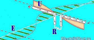
The reflector is the most important part of the antenna to increase its power
The reflector is the rear part of the receiving antenna. The main task of this device is not only to limit signal reception from the rear side, but also to amplify the received signal from the front side. How does this happen? The signal passing through the antenna is reflected from the reflector and returns back. It is important that the distance from the reflector to the emitter is a multiple of a quarter of the wavelength. In this case, the wave interferes with the emitters and is amplified.
It is important not only to choose the right material from which the reflector will be made, but also its geometric dimensions. The material must have good conductivity. Copper is best suited for these purposes. You can use foil getinax or fiberglass. Fiberglass is more reliable, since the copper foil is glued to it better. Various metal lids and boxes with uneven edges are not recommended, as the effect will be negative. In industrial production, copper mesh is used, but this option is more expensive from a financial point of view.
Biquad Wi-Fi Antennas
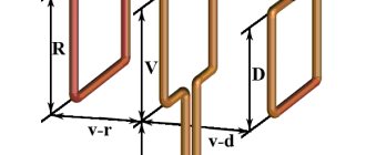
Strengthening the signal and transmitting it over long distances with a properly assembled antenna - up to 2 km in urban areas - in the most common Wi-Fi range of 2.4 GHz is done using various types of directional antennas. One of them is biquad, otherwise called by the name of its designer, Kharchenko. It consists of the following elements:
- a transceiver frame in the form of a double (or a multiple of two) diamond;
- a reflector made of aluminum, galvanized steel or copper plate;
- feeder line, the role of which is played by a coaxial cable with a characteristic impedance of 50 Ohms;
- connectors and adapters.
Use 5 GHz band
Budget WiFi devices operate on the 2.4 GHz frequency, so the 5 GHz band is relatively free and has little interference.
5 GHz is a promising range. Works with gigabit streams and has increased capacity compared to 2.4 GHz.
In practice: “Moving” to a new frequency is a radical option, requiring the purchase of an expensive dual-band router and imposing restrictions on client devices: only the latest models of gadgets work in the 5 GHz band.
The problem with WiFi signal quality is not always related to the actual range of the access point, and its solution broadly comes down to two scenarios:
- In a country house, most often it is necessary to cover an area in free air conditions that exceeds the effective range of the router.
- For a city apartment, the range of a router is usually sufficient, but the main difficulty is eliminating dead zones and interference.
The methods presented in this material will help you identify the causes of poor reception and optimize your wireless network without resorting to replacing the router or the services of paid specialists.
Found a typo? Select the text and press Ctrl + Enter
Create it yourself
Assembling such a device is not difficult, but it will take some effort.
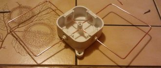
Biquadrat
To assemble such a device you need the following materials:
- wire;
- coaxial cable;
- wooden slats;
- pliers, hammer, knife.
Note! Before assembling the antenna, you need to carry out a qualitative calculation. There are specialized sites on the Internet that offer online calculators
Alternatively, you can use this site.
Assembly steps:
- Calculate concepts such as polarization and wave frequency. Maintain linearity.
- Make a vibrator and reflector from copper. All parts must be in the corners, one of which they touch.
- Select one side according to the formula: wavelength, which must be divided by four.
- Assemble the structure. It is recommended to make an oval shape without pulling the sides together.
- Attach the antenna wire to the approach points on both sides. To block one direction of the diagram, you need to mount a fetal screen, which is also made of copper. It should be positioned at a distance of 0.175 mm from the working wavelength, and then placed on the wire braid.
Ultra-long
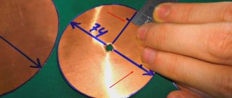
A fairly common name for such a catcher is “gun”. It is assembled from several steel disks with different diameters, which are secured with pins. Stages of assembly of such devices:
- The first step is to cut copper disks of appropriate diameters.
- Screw each of the disks onto special studs.
- Connect the wires to the last two plates.
- Connect the structure to the modem.
From an aluminum can
The simplest antenna, in which an ordinary can acts as an amplifier. To create it you need to cut off the lid. The result will be a barrel-shaped figure. Then you should strip the two ends of the wire: solder one to the bottom of the can, and connect the other to the antenna connector.
Powerful from sheet metal
In this case, the reflector is created from a metal sheet, which is recommended to be rounded. There are no special requirements for the vibrator; a biquadrat can be used. If there is no steel, it is recommended to use plywood or cardboard, which is wrapped in foil. The gain in this case will be slightly less.
A Wi-Fi antenna, even one you assemble yourself, will allow you to use your friends’ wireless network over long distances. There are several types of catchers. The choice of a specific one depends on the distance and terrain, as well as the user's tinkering abilities. In fact, everything is easy and simple, the main thing is to understand the assembly diagram and calculate the parameters.
How to make a biquad for two frequencies
The main element of the device is a copper wire with a diameter of 3-5 mm. It is not recommended to take a thinner one, since the external antenna is affected by wind loads and precipitation, and a thicker one will require recalculation of the geometric dimensions.
The calculations are based on the frequencies of channels (multiplexes). How to make a calculation? The signal frequency must be converted to wavelength using the formula:
λ= 300/f
,
where f is the signal frequency in megahertz.
The wavelength is calculated for each channel, and for further calculations the average value is taken.
The side length of a square is one quarter of the average wavelength.
Channel numbers and, accordingly, their frequencies vary in each region. This is done to reduce mutual interference. Correspondence tables between channel number and frequency are freely available. Typically, the tables show the values of the upper and lower frequencies. For calculations, the average value is taken. As an example, consider the calculation of the antenna for digital channels (abbreviated TVK) No. 32 and 36.
In accordance with the table, the channel frequencies are:
- Channel 32 – 558 – 566 MHz;
- Channel 36 – 590 – 598 MHz.
Channel frequency values for calculation:
- Channel 32 – 562 MHz;
- Channel 36 – 594 MHz.
Wavelength:
- Channel 32 – 0.53 m;
- Channel 36 – 0.50 m.
The average wavelength for calculating a two-channel antenna will be 0.515 m (51.5 cm).
Before making the antenna, the wire must be carefully aligned. If it is covered with insulation (cotton or fiberglass), it must be removed
Please note that a homemade antenna is made from a single piece of wire
The length of the side of the Kharenko antenna square is ¼ wavelength. For the example above this would be 12.9 cm
At the corners of the squares, the wire bends at an angle of 90 degrees. In the places where the coaxial cable is connected, the distance between the elements is 10-15 mm.
The cable is cut using the following technology:
- At the end of the cable, remove the outer insulation to a length of 50 mm.
- Carefully unravel the braid and twist it into a flagellum.
- At a distance of 40 mm from the end of the cable, the internal insulation is cut and the central core is freed.
The finished figure eight is attached through insulating stands to a reflector - a reflector made of a metal plate. This achieves the following:
- one-way directionality;
- increased noise immunity;
- increase in gain.
The size of the reflector should be slightly larger than the butterfly in height and width. The distance from the wire to the reflector is 1/7 of the average signal wavelength, for our case it is 51.5/7 = 7.35 cm.
External Wi-Fi antennas. Myth or reality?
At the moment, all kinds of Wifi antennas for laptops are quite widespread. These are devices that allow you to amplify the received and outgoing signal from a wireless network. They can be used to better capture the signal from your own router or router, as well as to use the signal of a friend or relative who lives at a certain distance.
Some people purchase such devices in order to intercept someone else's signal. However, this is a controversial decision, since the owner of the access point can easily block access to outsiders upon identification.
Note! External antennas are considered much more efficient than their internal counterparts
A standard Wi-Fi signal from any device has a certain range. Without various amplifiers, it is impossible to catch remote Wi-Fi.
Such antennas can be used to share one access point between several people. In such cases, internal products or directional external ones for longer range are suitable.
Important! Previously, such catchers were used exclusively for radio and television signals. Today, similar devices are used to improve the quality of mobile Internet and Wi-Fi
Equipment of any type to improve the quality of access, both Wi-Fi and mobile Internet, has a certain radius or effective range. In cases where the subscriber is outside the detection zone, laptop antennas are used.
Outdoor testing
You can install and direct a gun on the street to any place and move away from it at a certain distance. This makes it possible to check what signal transmission range it has.
Test results carried out by amateurs showed excellent signal quality at a distance of 300 m. At greater distances, the communication level became slightly lower, but data transmission continued. As a result, the range limit was 3 km. After this, the phone could not find the required network.
Interesting! The antenna power of the smartphone itself is also important. For example, the use of similar guns to receive and transmit signals makes it possible to exchange data at a distance of up to 10 km.
Having considered how to make a Wi-Fi gun, carrying out the necessary calculations and installing it, you can come to the conclusion that with its help it is easy to set up the Internet in a country house, garage, country house or any other place remote from the city. The device is suitable for distributing a signal to friends or acquaintances within the city at a distance of up to 1 km, if there is no serious interference.
Materials and tools
Before moving on to the instructions on how to make a biquadrat on Wi-Fi, you need to decide on a set of tools and materials that will definitely be needed during work:
- pliers, duckbills, side cutters (nippers), metal scissors, knife, soldering iron or soldering station;
- solder, flux, soldering acid;
- copper wire with a diameter of 1.8 mm (section 2.5 sq. mm);
- sheet metal up to 1 mm thick (aluminum, galvanized iron, even one-sided foil PCB will do);
- coaxial cable with a characteristic impedance of 50 Ohms;
- connector (if required, with an adapter) for connecting to a router, less often N-type, more often RP-SMA.
Important! You should be very careful about the type of connector, because RP-SMA and SMA are structurally identical, but at the same time they are physically incompatible; you need to choose it specifically for your equipment
Options for homemade designs: general principles
Depending on the distance between your TV receiver and the transmitting antenna of the television center, the signal level will change. Another negative factor affecting the quality of television wave propagation is the presence of obstacles. Ideal reception occurs when there is a direct line of sight between the two antennas. That is, you can see the mast of the television center, even through binoculars. If there are buildings or tall trees in the path of the TV signal, there will be no reliable reception. However, waves reflected from other objects can be received by a TV antenna amplifier. If even weak waves do not “break through” to your house, you will have to make a mast. The network of television and radio broadcasting stations is located in such a way that you can receive a signal in any locality.
- Indoor antenna. Operates without an amplifier in relative proximity to the transmitting mast. If you can see the television center from your window, some of the channels can be caught literally with a piece of wire. How to make a television antenna with your own hands can be seen in the illustration.
The quality of workmanship in such conditions affects only the aesthetic component. But if you live on the 1st–3rd floor, and even surrounded by concrete boxes of a residential neighborhood, a simple design will not work. An indoor antenna, especially one made by yourself, will require a signal amplifier.
Information: Indoor version, these are not necessarily the classic “horns” installed on top of the TV receiver. The product can be located on the wall, in a window opening, inside a glazed loggia.
The advantage of this design is that there is no need for weather protection.
- Street TV the antenna may look exactly the same as an indoor one. In this case, a prerequisite is high strength (so that the wind does not change the geometry) and protection of the contact group from corrosion. It is usually placed in close proximity to the window (in high-rise buildings) or on the roof of a private household. The connecting cable is relatively short, so an amplifier is not required to reliably receive a digital or analog signal. Except when the transmitting center is far away.
The structure is accessible for maintenance and repair; this is an undeniable advantage of being located nearby. - Outdoor antenna for long-range TV. As a rule, this is a rather bulky design with a screen and additional elements that amplify a weak signal. An electronic amplifier is welcome, but with proper design it may not be needed. Perhaps to compensate for a long cable (there will definitely be losses in it). Such devices are mounted on the roofs of high-rise buildings or on masts in private households. The fastening must be strong, otherwise the wind can easily destroy the structure.
- The antenna type is selected based on the reception characteristics and wind load in the region. For example, the Kharchenko antenna (the most popular homemade option) should not have a high windage. It may be necessary to choose another, more complex project.
Next, let's look at examples of making antennas at home using scrap materials, from simple to complex.
How can you increase the signal reception and transmission power of a router?
First, let's understand the terminology of devices that are used to receive and transmit Wi-Fi signals. In a normal situation, the provider provides the Internet using a cable or fiber-optic connection. After it, the owner of the house or apartment installs his own router, which receives this signal and then distributes it using a wifi connection. A router can also be used to distribute the signal over wires, but modern devices can combine both of these functions in one device. But if you need to transfer the Internet even a short distance from home, a problem may arise. At a distance of several tens of meters, the signal may be lost. And then it needs to be strengthened. Often this problem can be solved by an external directional antenna for a router made by yourself. Without much difficulty, such a device can amplify the signal up to 10 dB. In addition, there are separate receivers for such a signal. They have the name access point. If you use an antenna for such a device both for signal reception and transmission, then the maximum signal can be transmitted over a distance of 10 km. Provided line of sight of both devices is ensured.
Connecting the router to the computer
When combining several WiFi access points into one network, a conflict in IP addresses may arise, which is why it is first necessary to vary the IP address of the WiFi device, which in the future will function as a “repeater”.
To do this, we connect an access point to a computer or laptop via twisted pair cable. Although you can change the router settings via a WiFi connection, it may be that your device does not support such capabilities. Another nuance, in older models of routers, may be that the LAN cable will have to be connected to port number 1 on the router in order to configure it.
By the way, power is connected to the router directly by the power supply or thanks to a POE injector. It all depends on the specific model.
This is interesting: Connection diagram for an intercom (video intercom) in a private house - option with or without an electromagnetic, electromechanical lock
Types of WiFi antennas
There are two main types of antennas for WiFi routers: for outdoor use and indoor use. Outdoor routers tend to be larger. Also on their cases there are special fasteners that allow you to fix the device on a surface or support. Outdoor class models are used to transmit a signal from one point to another over a long distance. For uninterrupted communication it is necessary that there are no obstacles between these points. Devices for indoor use (apartments, private houses, offices) are less powerful and have smaller dimensions. Some models have fastenings that can be used to fix them on the wall.
Outdoor and indoor antenna use
- Outdoor antennas are those that are designed to work outdoors. They are protected from the effects of precipitation and sunlight and have special fastenings for installation on the wall of a building. They will be needed if you want to create a secure reception area in the yard or for communication between neighboring houses.
- Indoor antennas - for indoor use. For example, if your router is installed in a remote or closed place, then such an antenna can be connected with a cable to the antenna connector of the router and brought to the center of the room.
Directional wifi antenna
This is the most used type. An antenna that directs a wifi signal in a certain direction, for example, from a house to a personal plot, or to the balcony of a neighboring house, if we are talking about an external directional wireless antenna. Their range of action can be from one to several km. The main thing is that the reception source is in direct line of sight.
Internal directional wifi antennas for a router will be useful if, for example, it hangs on the wall. To prevent radiation from reaching the wall, you can connect it to the router and point it towards your desktop, on which the laptop is placed. Or vice versa, point the antenna at the partition so that the signal passes through it more confidently, providing stable communication in the next room. A very successful design of such an antenna is a panel rectangle that emits a radio signal in one direction.
There are also compact models that are suitable for both indoor use and outdoor mounting.
How to connect
Connecting any antenna occurs in several stages:
- The first thing you need to do is find the most suitable place for installation. If everything is clear with the internal device, you can install it on a windowsill, closer to the window, but the external one should be on the roof of the building or in another elevated place so that it can be directed as accurately as possible to the access point. In addition, it must be fixed vertically or horizontally, depending on the type;
- After this, you need to connect the external product to the amplifier, if provided by the design, or directly to the laptop;
- You need to connect the mobile signal amplifier to power.
- Test the received signal in the laptop. The number of communication divisions should be maximum in all places where the operating range extends.
How to assemble a WiFi antenna
With our own hands we cut out a square plate with a side size of 110 mm from a textolite plate. We drill a hole strictly in the center for the copper tube. The diameter of the hole and tube must be the same. The plate must be drilled from the side of the copper coating. Along the edges of the hole, you need to tin the copper surface with a soldering iron. This will be a reflector. On a copper tube from one edge we grind one side along the diameter by 2-3 mm. We insert the tube into the reflector so that the ground part is on the side of the copper coating. The distance from the reflector to the end of the tube must be 16 mm.
We cut off 244 mm of wire and strip it of insulation. We make superficial cuts every 30.5 mm. After this, follow the marks and bend it at a right angle so that it looks like the number eight.
Reflector
As mentioned above, a reflector is an ordinary metal plate; during manufacturing, the following features must be taken into account:
- When cutting off a workpiece, you need to remember that there should be no bending of the material;
- in the central part, after drawing diagonals, it is necessary to drill a hole in advance for the diameter of the insulation of the main core of the coaxial cable;
- The edges of the plate must be sanded or sanded, removing burrs.
Wi-Fi antenna - gun
This version of the transmitter is very powerful, like a real gun. The antenna-gun can resemble a space blaster, and by analogy with this fantastic weapon, it has a directional and very strong effect.
It is the directionality to one point, as the basic principle of operation of a Wi-Fi antenna, that allows for a fairly large distance of reception and transmission of signals, since there is a high concentration of pulses in one direction.
To make such a device yourself, prepare:
- long metal pin;
- 18 nuts of the corresponding diameter;
- metal sheet, for example copper;
- Wi-Fi adapter (however, you can connect an already installed router).
Instructions on how to make a powerful Wi-Fi antenna will be as follows:
- take a metal sheet and mark the centers of each circle (seven circles in total, the first with a diameter of 9 cm, the second 6.8 cm, the third 5.4 cm, the fourth 3.8 cm, the remaining three - 3.7 cm);
- drill the center (the diameter of the resulting holes should be slightly larger than the diameter of the stud);
- using a compass, draw circles on the metal and carefully cut them out;
- cut off the excess from the hairpin, leaving a length of 18 - 22 cm;
- place the circles on the stud one by one and secure them with nuts;
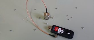
- in the last two circles, drill holes for the cable;
- we tin the disks;
- pass the cable through the hole in the last circle and solder the shielding winding to the metal;
- pass the middle core of the cable through the hole in the second disk and solder it;
- Screw the existing Wi-Fi adapter to the output of the connector.
Before starting work, carefully study the photo of a Wi-Fi antenna of this type. This will make it easier for you to understand the essence of the whole process.
Antenna up to 50 kilometers
This device is not difficult to make with your own hands following the principle described above. The main difference is the large size of the reflector, approximately 35 by 45 centimeters.
Vibrators made of fiberglass are installed on it.
In other points, the diagram for manufacturing a Wi-Fi antenna capable of receiving and delivering signals at a distance of 50 kilometers will be similar to the step-by-step description of manufacturing a long-range antenna.
If you need to strengthen the received Wi-Fi signal, do not rush to visit stores with expensive routers and add-ons for them. It is possible to improve the performance of an existing antenna using additional reflectors and arrays.
Try to make a powerful transmitter with your own hands; it will receive and deliver signals much more efficiently and clearly even over long distances. The above instructions will help you make a powerful, long-range Wi-Fi antenna.
Antenna location
If we talk about the location of the frame above the surface of the reflector, you first need to decide on the distance between them. It will be a multiple of the value obtained by dividing the wavelength by 10. In the case of the 2.4 GHz frequency range, this value is a very convenient 5 mm. It is advisable to place the biquadrat on a plastic tube cut from the body of a ballpoint pen, inside which there are two non-contacting wires that connect the central core and the reflector (to which, in turn, a common braided wire is soldered) with two corners in the center of the resonator.
When it comes to the spatial position of the entire structure as a whole, everything is standard here - a pair of antennas should be directed as accurately as possible towards each other.
DIY antenna tests
The end of a job is better than its beginning, as it is written in a wise book. Therefore, after completing the antenna assembly, check the quality of its operation. Such tests were always carried out when new products were released. Therefore, it is important to check how the antenna is directed and what kind of radiation pattern it has. It is also very important to calculate the range at which you can make reliable reception, for example on a laptop. After this, you can summarize the work done and receive moral satisfaction from its result.
Tips and safety precautions
When making such precision equipment as a microwave antenna, it is recommended to take note of a few tips:
- Tip 1. When working with copper wire, when creating bends, you need to operate not with the external, but with the internal value of the length of the biquadrate edge described in this article - Lin = 30.5 - 3.6 = 26.9 (mm). With a tolerance of 0.5 mm, this value can be rounded to 27 mm. Also, to ensure verification, it is better to create a template drawing, for example, for a device, on a real scale, drawn with lines 1.8 mm thick, and then, by applying the future antenna to it, check the manufacturing accuracy.
- Tip 2. If the wire initially has small bends (waves), do not try to straighten it with pliers, this will not lead to the desired result. Instead, you need to find a wooden block and fix it on the table (clamp, screws, etc.). Put on fabric gloves and, stepping back from the edge of the wire 30 - 40 cm, firmly grasp it. The end must be taken with pliers, then from the beginning to the gripping point, bending the wire over the edge of the beam, pull it several times with force (in one direction). With this method, all minor irregularities will be completely eliminated. If the length of the leveled area is not enough, you need to repeat the procedure from the end of the leveled area and above, but placing pieces of hardboard between the jaws of the pliers so as not to scratch the copper.
- Tip 3. In the case when galvanized steel is used, soldering of elements must be done using soldering acid. If aluminum was chosen as the material, connections are made using rivets or threads (bolts and nuts), soldering this metal at home without specialized equipment is impossible.
- Safety precautions when carrying out installation and soldering work. The first thing to remember is that when working with metals you need to use safety glasses. If you plan to use machines with rotating elements (emery wheel), the use of gloves is strictly prohibited. Sleeves should be no longer than elbow length, and hair should be tied back with an elastic band or beret. The second important rule is compliance with standards when performing soldering. The room where work is carried out must be well ventilated. The use of safety glasses is mandatory. When rosin, flux or acid is exposed to high temperatures, vapors are formed that can enter the lungs, so it is advisable to use a tight-fitting respirator with carbon filters.
Drawing of a double homemade biquadrat
In addition to the above, it should be noted that when manufacturing an antenna for a certain frequency, it is very important to comply with all the dimensions given below (together with the drawing):
Design features and operating principle of MiMo antennas for 3G and 4G modems
- the initial value of the angle between the arms of the frame is 90 degrees, then when setting the gap it will change slightly to the desired value;
- the external length of each edge of the square is 30.5 mm, deviation is permissible within 0.5 mm, no more;
- the gap between the central bends is 1-5 mm, selected directly during setup;
- the reflector is made in the form of a rectangle with sides 100 x 120 mm.
Note! Once again, the importance of maintaining accurate dimensions should be mentioned. This means that the antenna must be absolutely symmetrical with respect to its central part, regardless of the length of the edges.
What do experts advise?
It is quite simple to amplify the signal; for this it is important to know certain subtleties and carry out the installation correctly. So, high-quality communication is achieved by observing the following rules:
- In order for the signal to be distributed evenly throughout the room, the router should be installed as close to the center of the room as possible;
- The equipment should not be installed on the floor or near heating radiators, as this will significantly impair communication transmission;
- The standard equipment of modern routers is usually omnidirectional, so it is recommended to purchase more powerful antennas;
- There are many methods that allow you to improve the signal yourself. The simplest is foil glued to cardboard and installed in the desired direction;
- The signal can be strengthened by replacing the adapter;
- If you install a repeater, this device will significantly increase the signal transmission range.
At the moment, almost everyone uses Wi-Fi, but not everyone likes the speed of the Internet. Fortunately, now there are many ways to improve the quality of transmission, where the choice of a specific one depends on various parameters. It is also recommended to clean the registry from time to time, clearing it of unnecessary information.
In the modern world, a wireless network – wifi – is widely used. For its operation, special equipment is installed - routers equipped with antennas. The latter come in several types, each with its own characteristics, advantages and disadvantages. When asking the question “how to make wifi faster,” you need to understand that there are different methods, both free and requiring investment.
What is the range of Wi-Fi antennas
Often the distance is the most important parameter, for the sake of which the garden itself is fenced. Therefore, the question: over what distance can wifi be transmitted is of paramount importance. Several factors play into range. First of all, this is a line of sight zone. There should be no obstacles on the path between the receiver and transmitter. These distances can be increased by raising them to a certain height. The second point is the size and number of emitters. And the last thing is the directivity of the antenna. In the following, we will look at two types of antennas and their main features.
But it is worth understanding the following: the narrower the radiation pattern of a particular antenna, the higher its gain. But at a large distance and a narrow radiation pattern, any swing of the antenna by the wind will lead to the communication being uncertain. Therefore, they try to find a middle ground between the gain and the width of the radiation pattern. In reality, a good gain would be around 12 dB.
What you need to know about antenna signal amplification
The science that studies the propagation of high-frequency electromagnetic signals is called electrodynamics. This is a rather complex section of physics, and many students studying it try to get rid of it as quickly as possible. It is this science that shows how a signal propagates and how it can be strengthened. But to create an antenna with your own hands, there is no need to explore all the intricacies of this science, but certain principles used for receiving and amplifying the signal must be known and understood.
An important point in understanding the essence of the issue is the frequency of the transmitted signal or its wavelength. The longer the wavelength and, accordingly, the lower frequency signal, the greater the obstacles it can bend. Thus, radio waves of the long-wave and medium-wave ranges can easily travel hundreds of kilometers. For centimeter waves, a distance of tens of meters can become insurmountable, especially if there is an obstacle along the way.
Advantages and disadvantages
Modern antennas, including those for the Wi-Fi standard, do not have any disadvantages, which was largely made possible thanks to the use of modern electronic components.
The move away from pin-type telescopic models made of metal, still used today in analog radio reception, has made it possible to significantly reduce dimensions, cost and weight. The main components from which antennas are made are plastic, its derivatives, and polymer materials.
Modern design and miniature size allow you to place it in any setting or even decorate it with interior items. A special connection interface makes the antenna as efficient as possible and minimizes signal loss at the connecting contacts. A large selection of models makes it possible to select a product that best meets the technical parameters of a specific coverage area.
What is needed for production
A long-range Wifi antenna consists of several parts:
- coaxial cable for wifi router;
- reflector to enhance the wifi signal;
- holder for wifi antenna.
- The cable is not an element you should skimp on. It is better to take goods from well-known and trusted brands: Ecoflex, Aircell and others. If the length is short, you can also use standard RG58 - losses will be minimal.
- The holder can be made from any plastic object of small diameter, shaped at least vaguely like a cylinder. The simplest and most affordable option for it is a toothpaste tube cap or a bicycle cap.
- To make a reflector you will need foil fiberglass, getinax or tin. It is better to give preference to the first: it is easy to find in electrical goods stores and the easiest to process, and an antenna made from it with your own hands will turn out to be very powerful. The ideal size is about 15 centimeters in length and width.
Beer cans (Pepsi-Cola cans work too)
Why is this material so popular?
Before making an antenna out of beer cans, make sure that there are no high-rise buildings between the television center and the reception point that could block the signal.
Despite the relatively high reception quality, this design does not have a high self-gain factor. Connecting a standard amplifier may not have an effect due to the complexity of selecting coefficients.
Necessary materials:
- Two identical liter beer cans, washed and dried. As a last resort, you can use half-liter ones, but the reception range will be reduced.
- Antenna cable RK-75 of the required length (a design with a wiring length of more than 10 meters will most likely not provide reliable reception).
- Antenna plug to match your TV.
- A dielectric fastening bracket for fastening cans: a wooden block, clothes hangers, a plastic pipe (metal-plastic will not work).
- Fastening elements: electrical tape, tape, or plastic clamps.
- Soldering iron, standard solder, flux for soldering aluminum.
- Knife, side cutters, sandpaper.
Read also: Height of sconces on the stairs
There is no point in describing formulas for calculating sizes based on the reception frequency; anyway, it will not be possible to change the sizes of the segments. This DIY antenna made from beer cans has been tested many times under various conditions, so we’ll just use a ready-made sample.
We cut the antenna cable. There will be a plug at one end, open the other end so that there is at least 100 mm from the central core to the screen wound into a bundle. To prevent the “bare” braid from being exposed to corrosion, it can be hidden in a heat-shrinkable casing.
We clean the areas for soldering the cable: at the upper ends of the cans. Fine sandpaper is suitable for this.
Stripping is carried out immediately before soldering and to the “bare” metal.
We roll each end of the wire into a ring 3–5 mm in diameter and carefully coat it with solder. Then we screw the resulting terminal to the can using a galvanized self-tapping screw. After that, we clean the joints with flux and solder until the solder “sticks” normally.
We fix the cans (from the point of view of the theory of radio reception, these are now symmetrical vibrators) so that there is exactly 75 mm between the ends with the cable. This is the optimal gap for receiving analog and digital television.
An important step: setting up the product for optimal TV signal reception. Most likely, you know the direction to the broadcast center tower. If not, Yandex cards will help you. Find a television center, your home, and conduct a virtual live broadcast. If you don’t want to bother with azimuth (this is impossible without a compass), determine the direction reference within your visibility zone. For example, a boiler room pipe or another object. For reliable reception, the home TV antenna is positioned strictly perpendicular to the vector to the tower, and horizontally.
If the signal is received reliably, you were lucky the first time. At a considerable distance from the transmitter, you can catch the reflected signal. Even a simple antenna made from cans requires correct orientation in space (although it is not a satellite dish). In an area of uncertain reception, all-wave technology can unexpectedly “shoot” in any direction.
A do-it-yourself “beer” decimeter antenna allows you to confidently catch analogue channels. How to make an antenna for digital TV? No additional secrets. Digital broadcasting is produced in the same range. If you have a DVB-T2 tuner, you can tune in to one or two multiplexes, and receive a free set of Russian channels on beer cans.
If the signal strength is still not enough, you can make an antenna amplifier yourself.
Typical diagram in the illustration:
However, in order to solder and configure such a device yourself, basic knowledge of radio engineering is required. Still, it’s easier to buy a ready-made device, especially since you’ve already saved on the antenna.