A power limiter is a device that regulates the flow of electricity to your home. It usually works on an alternating current network. Thanks to modern limiters, the service life of low-power transformers can be significantly extended. They also help regulate energy consumption between users. Additionally, limiters can be configured to prevent unauthorized connections. Today, all devices of this type are divided into single-phase and three-phase models.
Features of single-phase limiters
A single-phase power limiter has a voltage limit of 300 V. The operating frequency of the device is on average 60 Hz. The minimum limiters are capable of delivering a power of 3 kW, and a maximum of as much as 30 kW. However, in this situation, much depends on the manufacturer. Additionally, a parameter such as delay is taken into account. It ultimately affects the voltage limit of the device. The maximum current overload for single-phase limiters can be 3 A. It should also be taken into account that sudden voltage surges are unacceptable for devices of this type.
Operating principle of power limiters
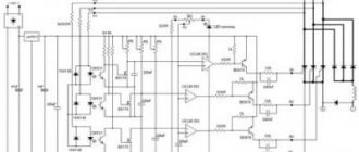
The design contains a transformer unit; it is very sensitive to sudden surges and changes in electric current and voltage. This equipment constantly monitors and scans the obtained indicators.
He transfers them to a special unit. Here, careful calculations of electrical power consumption indicators are made. When a deviation in the parameters is noted, a signal is sent to the power supply, which disconnects all electrical contacts from the power center.
What to do in this case? It's quite simple. First of all, it is recommended to unplug all household appliances that have been turned on in the last 30 minutes. It was this equipment that exceeded the permissible operating standards of the electrical network. Next, you need to de-energize the central electrical panel for 10 minutes. This will allow the system to adjust to the desired level of rated current supply.
When all criteria are met, the system normalizes the process of supplying power to the living space. What is included in the structure of the limiter? The following types of parts are distinguished:
- semiconductors;
- inertial relay;
- controller in the form of a microprocessor.
All these parts control the supply of electricity and prevent premature breakdowns of household equipment. This set of parts ensures uninterrupted supply of rated voltage.
What is the difference between three-phase limiters?
The power limiter (three-phase) keeps the maximum voltage at 350 W. In turn, its operating frequency is at around 70 Hz. The minimum limiters are capable of holding a power of 5 kW, and a maximum of as much as 40 kW. Additionally, it should be taken into account that they have a fairly high discreteness rate.
The shutdown delay, in turn, averages about 10 seconds. Three-phase modifications can withstand quite large power overloads. Voltage drops are also perceived as severe. Among the disadvantages of these devices, it should be noted that the current in the relay contacts is highly unstable. Additionally, there are large errors in measurements. Thus, three-phase limiters require more serious adjustment.
What is the purpose of a power limiter?
Many people are familiar with network voltage limiters. This is a protective device that controls the amount of input voltage along a predetermined “corridor”. Such devices can be found in many apartments or households.
The voltage relay really protects electrical appliances from power surges, but that’s where its functions end.
A power consumption limiter (single-phase or three-phase) works on a different principle. More precisely, it has wider functionality:
- Just like a voltage relay, the device monitors the input parameters of electricity. If the value is outside the set parameters, the power to the object is turned off. At the same time, electrical appliances are preserved. After returning to normal, power supply is restored.
- Control functions during operation of electrical installations. The power limiter can maintain parameters to prevent emergency situations.
- Protection against unauthorized connections to your electrical network. You can set strict limits on power consumption on the line, and control your network with an accuracy of 10 W. If an illegal power take-off occurs, the device will turn off the power grid.
How to connect the device?
The power limiter is usually connected above the input machine. In this case, the high-voltage wire should be located near the starter. The zero bus is directly connected to the electricity meter. The connection to the transformer is made in series. For normal operation of the limiter, the block is first set.
The power connection is checked for each phase separately. The top pads should ultimately all be in the top position. The electromagnetic latch is turned on last. The second line blocks must close all relay contacts. To avoid any overload, the device is equipped with a special alarm. The last pair of pads is necessary to set the desired mode. After securing the limiter, the tubular entries are checked, as well as the main power wire.
Related links
- Rules for the technical operation of consumer electrical installations / Regulatory document dated February 9, 2007 at 02:14
- Electrician's Bible / Regulatory document January 14, 2014 at 12:32 pm
- Handbook on electrical networks 0.4-35 kV and 110-1150 kV. Volume 10 / Regulatory document from March 2, 2009 at 18:12
- Kabyshev A.V., Tarasov E.V. Low-voltage circuit breakers / Regulatory document dated October 1, 2022 at 09:22
- Rules for the installation of overhead power lines with voltage up to 1 kV with self-supporting insulated wires / Regulatory document dated April 30, 2008 at 15:00
- Knyazevsky B.A. Trunkovsky L.E. Installation and operation of industrial electrical installations / Regulatory document dated October 17, 2019 at 12:36
- Mankov V.D. Zagranichny S.F. Protective grounding and grounding of electrical installations / Regulatory document dated March 27, 2022 at 09:05
Read with this
- 2 schemes
- How to install a limiter on a plastic window with your own hands
- How to install sconces correctly: step-by-step instructions and installation tips
- Why a vacuum circuit breaker
- Connecting the plug to the hob
- Uninterruptible power supplies for heating boilers of any type
- Connecting the hob to the electrical network: diagrams, selection of cables, sockets, machines
- How to connect a washing machine yourself: step-by-step installation instructions
- Twisted pair or how to connect an Internet outlet: 7 stages of installation
- How to glue fiberglass correctly?
Limiter OM-630
This device is connected via a 35 mm rail. The OM-630 power limiter can withstand the maximum voltage at 300 V at an operating frequency of 60 Hz. The device can produce a minimum power of 4 kW, and a maximum of as much as 30 kW. The discreteness indicator of this model is good and is at the level of 0.2 kV. The restart delay is on average 5 seconds. If there is a sharp drop in voltage, the OM-630 power limiter can turn off quite quickly. The device can withstand a maximum current load of 5 A.
Specifications
No description of devices is complete without information about technical characteristics. OIN-1 has the following characteristics:
- Withstands voltage up to 275V for a long time, at a standard frequency of 50 Hz.
- Installed on DIN rail.
- The width is 17.5 mm, which coincides with the dimensions of a single-pole circuit breaker.
- During operation, it consumes a current of 0.7 mA at 275V.
- It complies with GOST standards and has been certified, so it can withstand pulses up to 10 kV, with Is = 5000A.
- There is a version OIN-1S, equipped with a light indicator for the presence of voltage in the network.
- Terminal blocks allow you to connect current-carrying conductors from 4 to 16 mm.
Device model OM-1
This model is connected via a special bus, which is located under the meter. The specified power limiter (diagram shown below) can withstand a maximum switching current of 16 A. The device can be adjusted from 3 to 30 kW. The degree of protection in OM-1 is IP20. The total restart delay is around 6 seconds. The specified limiter is capable of working with an external AC transformer. If there is a sudden voltage surge of 20 V, the device turns off automatically. Additionally, it should be noted that this limiter is quite easy to install. This is due to the fact that the kit includes a special rail on which the case is attached.
Installation Requirements
Both the consumer and the electricity supply company are interested in installing a power limiter. The value of the supplied electricity must be within the established limits (voltage, frequency, power).
This device must be installed and connected by a trained electrical technician. In case of self-installation, the following factors must be taken into account:
- Single-phase or three-phase voltage.
- Contractual load power (kW).
- Response time when the specified parameters are exceeded.
- Time to return to the original state.
The type of device that needs to be purchased depends on the first parameter. The second parameter also needs to be known to determine the type of power limiter to be purchased. An additional contactor may be required. The third one will make it possible to adjust the power parameters of the connected load if a specified limit is accidentally exceeded - this parameter can be configured. The fourth will remind the consumer of the violation and allow him to adjust the total consumption of connected consumer devices and, if necessary, turn them off.
To install and install all types of limiters, you must comply with the general requirements:
- Use a wire of the required cross-section, which is calculated based on the consumed load.
- Contactors must be rated for current consumption.
- Limit access to live parts due to the high probability of injury from electric shock.
- The settings of the limiter should be carried out taking into account the planned consumption, and not to the maximum values.
- In the event of multiple protection activations, check the technical condition of electrical appliances for poor insulation and short circuits.
- If the device malfunctions, call a specialist.
Connection of limiter OM-1-2
The power limiter OM-1-2 is connected via an input circuit breaker. The high-voltage wire should be located behind the device cover. First of all, it is important to connect all contacts to the electricity meter. Next, you need to configure the zero bus in the panel. Lastly, the starter is activated, which is located above the zero-sequence transformer.
The first three limiter pads are connected directly to the relay. In order for the pulse to pass, a separate contact on the panel is activated. The second line blocks are used for external signaling of the limiter. The device's tubular entries are checked last. To set the required mode, the outermost pair of pads is used.
Connection diagram for single-phase model with electric strike
In this case, the first pair of pads should be in a neutral position. Connection to the power supply is made through a special connector. In the first phase, the voltage is checked first. For the electromagnetic latch, relay contact K1 is used. The second line pads in the limiter are designed for priority load. To access an external alarm, contacts of different powers are used. The third line pads are intended solely for setting the mode. The tubular inputs are directly connected to the power cable.
Connection diagram with closed contacts
Connecting a limiter with closed contacts involves the use of discrete switches. The display system is checked using special LEDs. This way the user has the ability to control the voltage limits. External signaling plays a key role in this case.
In order for the limiter to be able to withstand a larger load, the first pair of pads is placed in the neutral position. The starting pulse in the system is suppressed by an electromagnetic latch. The second line pads are necessary solely to overcome the priority load. In turn, power is turned off due to the zero bus. A switch that connects to the zero phase closes the circuit in the network.
Devices OM-630-2
The power limiter 630-2 can withstand the maximum voltage at 340 V at an operating frequency of 70 Hz. Its discreteness indicator is 3 kW. The device is connected to the meter through closed contacts. The shutdown delay during overload is on average about 40 seconds. This limiter can withstand a maximum voltage drop of 30 V. In turn, the system can handle an overload of 5 A. The measurement error of these models is quite small, and this should be taken into account. Additionally, it is important to note that the limiter is re-engaged quickly.
The lineup
The table shows the main characteristics of devices produced* by Russian and foreign (St. Petersburg), "Meander" (St. Petersburg), "Euroavtomatika FiF" (Lida, Republic of Belarus)
Name Manufacturer Power Eg. power supply Contact OM-1 Euroautomatic 3-30 kW 50-260V 2x8A OM-1-1 Euroautomatic 1 -16 kW 50-450V 75A OM-1-3 Euroautomatic 1-10 kW 230V 16A OM-3 Euroautomatic 0.5-5 kW 230V 16A OM-611 Euroautomatika external CT 230V 10A OM-63 Meander 1-14 kW 50-400V 8A OM-110 Novatek 0-20 kV 130-300V 8A
Three-phase power limiters
Name Manufacturer Power Eg. power supply Contact OM-630 Euroautomatic 5 -50 kW 3x400/230+N 2x8A OM-630-1 Euroautomatic up to 50 kW 3x400/230+N 2x8A OM-630-2 Euroautomatic external CT 3x400/230+N 2x8A OM-310 Novatek 2 ,5-30 kW 180-450V 2x8A
Data presented as of May 2016.
Please note that the maximum permissible contact current is 8 - 16A. This is explained by the small dimensions of modern power limiters and the inability to place power relays in the device housing
To connect subscribers, external contactors designed for the required current are used. The exception is OM-1-1, capable of switching loads up to 16 kVA with a built-in relay.
The photo below shows examples of installation of power limiters for operation in single-phase and three-phase networks, using external contactors.
Euroavtomatika FiF produces a wide range of power limiting devices, both single-phase and three-phase. The best-selling of them is OM-630, detailed information about which can be read on the thematic website www.om-630.ru
A special feature of OM-630-1 is the ability to configure using a personal computer. All parameters: power value and calculation option, shutdown and restart delay, output relay operating mode, are set programmatically when connected to a computer via a USB port.
Among the Novatek Electro products, the OM-310 stands out - a multifunctional device with impressive performance characteristics, rich equipment, a huge number of settings, remote control capabilities, data transfer via the MODBUS protocol and... instructions on 27 pages. In my opinion, it is the excessive complexity that prevents it from achieving the popularity of the OM-630.
Connecting the OM-630-3 device
This power limiter is turned on (the connection diagram is shown below) via the bus. In this case, group semi-automatic devices are connected last. The upper pair of pads must be in the upper position before applying current. In turn, the second line pair should be in a neutral position. Thanks to this, the voltage in the device quickly stabilizes. To combat priority overloads, special blocks are used. They are attached directly to the electricity meter. You can always check whether the limiter is connected correctly based on the indicators of the display system.
How to install OM
It is very important to connect the electrical power limiter correctly. Please note that a device with one phase is connected to only one contactor, in the same way with three - to several. Otherwise, you risk damaging the limiter due to incorrect connection to the output terminal.
Photo - identification of structural details
Almost any OM has a built-in transformer, since it is an adjustable device. The power limiter is connected only by pulling the network cable through a transformer. Accordingly, voltage and power calculations are made based on local electrical network data. The general diagram for connecting the limiter is as follows:
Photo - connection diagram OM 1-3
For three-phase limiters 630 (in the diagram the device designation does not change - OM):
Photo - OM 630
In most cases, both European and domestic automation provides the opportunity to determine independently at what speed the current will be switched off when the network power is exceeded. To do this, find the corresponding button with the designation on the outside of the limiter. Pay attention to other settings, change them if necessary; initially they are “factory” settings. You need to install the device on a DIN rail, this way you will ensure the tightest possible fastening and at the same time save space in the panel panel.
After installation work, the device needs to be configured. To do this, it is advisable to use the manufacturer's recommendations. For this OM, for example, it is advisable to set the latch near the letter “K” to 10. This action will help to effectively increase its operating range to 20 kVA, without the danger of combustion. The rated power must be set according to your needs.
If everything is done correctly, a green lamp will light up next to the “Load” diode, indicating the start of work. If this does not happen, then check the connection of the contacts again so that only one cable goes to one contactor.
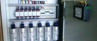
Sometimes, for greater convenience, a panel with a power limiter (PSL) is initially installed, on which the meter is mounted. Such a system will help to significantly reduce the time spent on installing individual devices, as well as remove protruding wires and save space in the panel.
Single-phase model OM-310
To connect this model to the network, a 35 mm rail is used. The power limiter 310 is designed for a voltage of 250 V at an operating frequency of 45 Hz. The minimum power can be set to 5 kW, and the maximum to as much as 33 kW. The resolution of this limiter is quite significant and amounts to 0.3 kV. In turn, the shutdown delay is 6 seconds. The device restarts quickly. The maximum voltage drop OM-310 can withstand is 5 V. In turn, the current overload should not exceed 6 A. There are two switches in the device.
What are the dangers of exceeding
If you were connected to the network bypassing the meter or used electricity without a contract, your power consumption is calculated based on the maximum current that can flow through the input cable in the period since the last check. And the restriction will not be lifted until the debt is repaid and (or) the reasons for exceeding the capacity permitted by technical conditions are eliminated.
Important! A report on unaccounted electricity consumption is drawn up only in case of connection without a meter or bypassing it. And it is compiled with the involvement of two disinterested persons and video or photographic recording of the process
In simple words - until you disconnect the “extra” consumers, return the circuit breakers to the ratings specified in the contract, and so on. Fines for excess electricity consumption (read as non-compliance with the terms of the contract) may be provided for in contracts with the energy sales company.
Devices for working with an external transformer
A power limiter of this type is usually connected using a 40 mm rail. In this case, the input machine should be located under the box next to the power cable. The device is connected to the electricity meter last. The zero bus is connected to the first two contacts, which are normally open.
It is additionally important to install a starter that regulates the operation of the zero-sequence transformer. Before this, the user must configure the first pair of pads on the device. To do this, they should first be set to the upper position and then look at the display system. If the green LED lights up, it means the system is closed. Next, these pads are moved to the neutral position so that the signal passes unhindered. Then the relay contacts are configured.
First of all, they should be thoroughly cleaned. In this case, tubular inputs are supplied to them in series. Next, it is important to close the electromagnetic latch. For this purpose, it is necessary to remove the protective cover to the side and move the circuit wiring. The blocks of the third line are set to the top position one by one. In this case, the user is obliged to monitor the display system. If the green LED lights up during the procedure, this indicates that the circuit is closing. To prevent external alarms from being activated in the system, you need to disconnect the relay contacts. The tubular entries must then be reconnected.
How to connect OIN-1 in the panel
This device has a number of functional analogues from all popular electrical equipment manufacturers, therefore their connection diagrams are basically similar. In the official documentation, the connection diagram is not too obvious; it is presented in two versions and looks like this:
Please note the first option is to connect in parallel to the protected circuit, and the second is to connect in series with the disconnector. That is, as a result of the operation of the surge voltage limiter, the disconnector must break the power circuit in order to avoid the product igniting and current flowing through the electric arc
But the given diagram is not at all clearly or clearly depicted, and the question immediately arises of how to properly install the device. Therefore, check out several examples of connecting an SPD to the electrical network.
The figure below shows a typical diagram of the conditions for connecting 3 phases. The connection of voltage limiters to the meter is shown here more clearly. In a three-phase circuit with a TN-S or TN-CS grounding system, it is connected between phases, neutral and ground. But connecting OIN-1 after the meter is also acceptable as an additional level of protection.
Installation diagram using an example of connection in a two-wire electrical network:
And finally, let's look at the diagrams for four different power supply schemes (1 phase, 3 phases, combined and disconnected protective conductors), which are most common: