During electrical installation work, a lot depends on the convenience and reliability of switching connections. Twisting does not provide a reliable joint, and connections using bolted elements are not always convenient. Therefore, for these purposes, a cross-module is used, which is also called a modular distribution block (MD).
Model range BLOX
Why is RB needed?
The main purpose of the distribution block is to distribute electrical cables across sections. That is, it turns out that one input cable enters the device, and several wires of a smaller cross-section come out of it. By the way, the cross-section may be the same for each output cable, or maybe different. Everything will depend on the current load operating or planned at each site. In short, there is one input, several outputs to consumers.
Manufacturers today offer several design models that are installed on different network circuits.
- To the zero bus.
- To phase.
- Combined option.
Example of connections using a cross-module
The simplest design is zero. This is a device in a plastic case, inside there is a copper bus separated by plastic partitions. The wires are fastened to the bus using screws. The latter can be for a screwdriver or a wrench.
The phase design exactly repeats the zero one. But when manufacturing devices of this type, manufacturers take into account that they will operate at a voltage of 1000 volts under a current load of 500 amperes. It should be noted that this type of device is made of special plastic. It is heat-resistant and self-extinguishing. As they say, safety comes first.
A combined crossover module is two identical parts in one housing. That is, both the network phase and the zero can be passed through it simultaneously. For distribution boards in which a large branching is installed across sections and there are a large number of electrical appliances, this is the optimal solution. A diagram of such a connection will be discussed below.
What is interesting in terms of the module design. Its top cover is transparent. This is, firstly, beautiful, and secondly, you can visually see all, so to speak, the ins and outs of the device. Some manufacturers make holes in the covers for clamping screws. This is convenient because when tightening the contacts there is no need to remove the cover itself. There are no restrictions on wires (copper or aluminum).
Design
Rationale for use
There is an opinion according to which, when assembling an electrical panel, it is better not to use cable cross-connection modules, since they reduce the useful space in the distribution panel, that is, they clutter it. In addition, the cost of equipment increases.
There is some justice in this statement, especially considering that the overall price of the system will increase, albeit slightly. On the other hand, the use of cross modules provides undoubted advantages; let’s consider them:
accuracy of installation, to make it clearer, below is a photo showing distribution boards with and without cross-modules. There is no need to designate each of them; the difference is clearly visible.
An illustrative example: what the use of cross-modules gives
From the photo it immediately becomes clear where it will be easier to understand the distribution board diagram or, if necessary, reconnect the lines. So in this case, the aesthetics are quite justified;
low probability of short circuit; in multi-pole blocks, contact groups are separated by partitions
Please note that despite this, all electrical installation work must be carried out only with the equipment de-energized; fastening the wire to the bus ensures reliable contact, which eliminates heating at the connection point; a variety of models that allow you to implement connection diagrams of any complexity.
Connection
Installing and connecting the cross-module is not difficult. The case is simply mounted on a DIN rail, so it can be installed very quickly. Switching wires is also easy. The video below shows how to connect a crossover module, and also clearly demonstrates the advantage of using it:
Connection diagram
Advantage of installation
So we looked at what a cross-module is, why it is needed and what sizes this product comes in. Finally, we recommend buying a modular distribution block from trusted manufacturers: ABB, IEK, Legrand, Dekraft or Schneider Electric. The quality of materials plays a very important role in the operation of this device.
We also recommend reading:
- How to assemble a distribution board
- What types of DIN rails are there?
- Connection diagrams for a three-phase electricity meter
Selection rules
In order for the device to operate properly, for a long time and reliably, a competent choice is required.
When purchasing, you should pay attention to the following points:
Maximum current load of the distribution block. It should be noted that the use of smaller established values is not permitted. This is a determining factor at the time of purchase related to the safety of the device. The good thing is that there is protection on the linear side of the cross. Manufacturer. Well-known players in the market for such services are Schneider Electric, IEK, ABB, and other manufacturers. There is an opinion that foreign models are of higher quality and better than domestic options. This is debatable. Now a number of domestic companies have started producing equally high-quality products. Availability of a certificate for the product
When purchasing, you must ask for a certificate for the product, since such products are subject to mandatory certification. Attention is drawn to the dimensions of the device in accordance with the dimensions of the electrical panel in which it will be located. Naturally, the product should not have external defects. The price of the device has a certain influence on the choice. There are a large number of options and everyone chooses a model in accordance with their financial capabilities.
Modular distribution block: its functions and advantages
The main purpose of the modular block is to branch conductors to the required areas. It clearly looks like this: one electrical wire goes into the device, and several come out, only with a different cross-section.
A cross-module or RB is needed to simply and most conveniently distribute power in the panel. Most often this is needed in those shields where there are three phases. This is due to the need to avoid connecting loops, and the ability to regulate the load level on the phases.
Advantages of distribution blocks:
- Aesthetics – the module located on the DIN rail looks very neat and allows you to quickly find out where everything is;
- Safety of use – it is better for a person without experience to use abb cross-modules, which reduce the risk of a short circuit in the electrical circuit;
- Reliable and durable contact of conductors due to its special design;
- Large selection of permissible wire sections;
- Possibility to use the cable both with and without a tip;
- IP 20 class protection of the front part of the panel, which protects a person from accidental contact with the current parts of the device.
Design
A modular distribution block consists of a certain number of metal bars that are insulated from each other. The busbar material can be either electrical copper or brass. The design of the cross-module also includes screw terminals, thanks to which fast and safe switching of wires of different sections is carried out.
The housing of the distribution block itself is made of heat-resistant, self-extinguishing plastic, due to which such products are considered fireproof. In addition, the design of the cross-module includes a hinged cover, thanks to which the tires are protected from accidental penetration of foreign objects. The cover is made of transparent plastic, which makes it easy to inspect the distribution board.
It should also be noted that cross-modules come in several types: zero (for connecting neutral wires), phase and combined. The difference between a zero distribution block and a phase distribution block is that the latter is able to withstand a higher current load due to its design.
In addition, products can be single-pole (or as they are also called single-phase) or multi-pole (2, 3, 4 poles). Modular multi-pole distribution blocks are used to assemble three-phase switchboards.
As for technical characteristics, cross-modules are designed for different current loads: from 80 to 500 A. There are also differences in the cross-sections at the input and output. The input wire cross-section can be from 16 to 185 mm2, and at the output there can be 2 or more terminal blocks designed for different, smaller cross-sections. To choose the appropriate design option, you must first draw up a diagram of the distribution panel in order to know which wires will be switched.
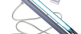
It should also be noted that there are crossover modules designed for switching digital networks: twisted pair or optical fiber. They are called optical cross-modules.
Types of cross modules
The distribution modules (blocks) are separated according to the cross-section of the wire, which is inserted into the terminal at the input. Of course, current load is also taken into account. Let's identify all the available positions, especially since there are not very many of them.
- RB-80 1P 80A. It is clear that such a device can withstand a current of 80 amperes. But we are interested in wire cross-sections. So, you can insert a wire with a cross-section of 16 mm² into this block, and output 4x6 or 2x16.
- RB-125. Input wire – 16 or 35 mm², output wire: 6x16.
- RB-160. Introductory: 16; 35 or 70 mm², output: 6x16.
- RB-250. Input: 120 mm², output: 4x10; 5x16 and 2x35.
- RB-400. Input: 185 mm², output: 4x10; 5x16 and 2x35.
- RB-500. This model has flat contacts. Input width: 15-24 mm, thickness 3-8. But the output terminals repeat the two previous positions.
Of course, such a wide range of models is required mainly for production facilities. In household electrical networks, the first position will be sufficient. Rarely is the second position used.
Design features
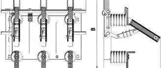
The design of the modules depends on their purpose. During electrical installation work, the following RBs are used for cross-connection:
- for the zero bus (PEN);
- phase (L);
- combined (L+PEN).
The design of the first is the simplest: a copper bus is placed in a plastic case, the fastening points are separated by partitions (made of the same material as the body), the wires are attached to the bus using screws.
Dimensions of Leg cross modules (LeGrand) for the zero bus: “A” – 2×7 and “B” – 4×7 connections
The design of phase modules is practically no different from those intended for the zero bus, with the exception of the materials used, since they must withstand a certain current load. For the same reason, the body of such structures is made of heat-resistant, self-extinguishing plastic.
Image of IEK cross-module (L-PEN stepped housing)
As for combined designs, they represent the two previous types combined in a single body. That is, with their help you can simultaneously switch both zero and phase (phases). Note that the use of such modules in electrical distribution boards with a large number of branches will be the most optimal solution.
Photo of a combined four-pole cross-module
Almost all manufacturers provide the contactor with a hinged cover to protect the contacts from foreign objects. Some make it transparent, so you can assess the condition of the contact groups without removing the cover.
It should be noted that cross-panels are used not only for branching electrical circuits. There are devices for cross-posting (switching) of a digital network using twisted pair or fiber optics.
Optical crossover module for 32 SC ports (LC duplex)
Such devices are installed in special structures - cross-connections, where there is a flat profile (strafe) for attaching plinths (modules) for a certain number of pairs.
Telephone multi-module cross-wall type
Wall-mounted dust- and moisture-proof cross-connect (CPW) for fiber optics with several APC-320SC/APC SSD VOKS-B modules
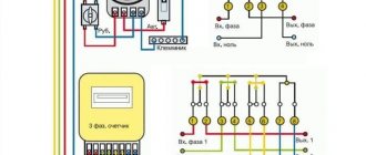
Cross module connection diagram
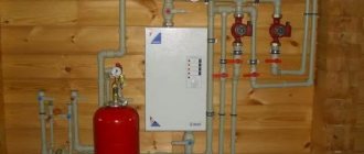
Why does the cross module make it easier to install a distribution board? Imagine a scheme in which a voltage relay is installed on every section of the building's electrical wiring. Let it be a single-phase supply network. How does it connect?
A wire is output from the meter, which is twisted and divided into several sections. A twist connects one large cross-section cable and several small ones. Not a very convenient contact. By installing a distribution block between the meter and the relay, you can make the circuit more convenient. This device will take up little space, but both the phase circuit and the neutral circuit will pass through it at once. In this case, there are no twists, no connection of large-section wires with small ones, and there is no installation through terminal distributors, where two or three wires are inserted into one terminal at the same time. In this case, like all devices, the cross module is installed on a DIN rail.
And one last thing. With such a device you can easily carry out diagnostics. It does this, you just need to disconnect the required (diagnosed) section from the electrical network in the cross module. If for some reason it is necessary to change the circuit for distributing electricity along the loops, then all this can be done in the distribution block by swapping the wires. The most important thing is that the wiring diagram itself does not change. That is, there is no need to change the location of devices and DIN rails, wires and connection points.
Mounting methods
In principle, there are only two mounting methods: on a DIN rail or with self-tapping screws. Of course, installation on a DIN rail is both modern and convenient. In addition, the fastening device can be mounted in such a way that several different types of electrical devices can be immediately attached to one element. True, in this case you will have to take into account the size of these devices and the convenience of laying the wires. But as practice shows, installation on a DIN rail is always easy. This is due to the ability to transfer its parts to different levels, cutting the element itself to a certain length. In this way, it is possible to achieve a compact installation of the switchboard itself.
Why do you need a cross module?
Standard situation: the input cable goes immediately to the input machine, after which it disperses into packets going directly to consumers. On the one hand, there are no violations in such a scheme, but further installation of electrical wiring may be slightly difficult.
Figure 3: Any cross-module consists of copper busbars
When installing a cross-module, the wires from the input machine first go to it, and then to the machines to consumers. This scheme is simple and convenient, since, firstly, the number of wires is minimized, and secondly, it becomes possible to quickly connect (disconnect) new lines.
Advice! When installing a new cross-module on a three-phase system, you must choose a product with a supply of holes, for example, a model with four busbars of 15 holes each. A small reserve will save nerve cells in the future, when you want to install a hob, install a boiler or connect a low-current line.
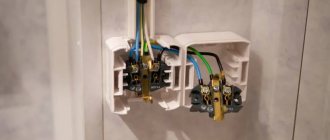
The four buses of the cross-module should be distributed between three phases and a working zero. It is best to attach the grounding separately, with appropriate markings. The entire installation of conductors to the cross-module is carried out simply and quickly: unscrew the fixing screw on the bus with a screwdriver, insert the stripped end of the wire into the hole and tighten and tighten the screw securely.
The cross-module is a convenient and safe product that will save a lot of time and effort in the future. It has an affordable price and a long service life - irreplaceable qualities for electrical products.
Characteristics of structural elements
Design features require the presence of a certain number of metal tires. All of them are isolated and do not touch each other. They are made from various materials. For this purpose, special copper is used, with certain electrical characteristics or brass. The design also includes screw terminals. Using such devices, you can quickly switch wires of different cross-sections.
The Legrand cross-modular device model 04888 is highly reliable in operation
The material for the body is plastic, which is heat-resistant and fireproof. Another structural element is a hinged lid made of transparent plastic. It protects against foreign objects entering the device body.
Advantages of distribution blocks
Some electricians have a negative attitude towards cross modules, believing that they clutter the distribution board, plus the extra costs of purchasing an additional element. Don't tell me, this block has several positive qualities.
- No one has yet canceled the aesthetic side of the matter. A cross module installed on a DIN rail in a shield is not only about the functionality of the device and the quality of the connection, it is about beauty. This was especially appreciated by electricians who offer their services for installing electrical wiring in private houses. The owners of such houses are willing to pay for beauty. And there is nothing reprehensible in this. In addition, everything inside the shield falls into place, it becomes neat.
- A monolithic contact bar is located inside the distribution block. It is usually made from tinned copper or brass. And if the shield itself is assembled by a beginner, then the possibility of shortening the zero phase through the block simply will not work. Of course, short circuit is an extreme situation, but for those whose hands grow from the wrong place, it is recommended to use cross modules.
- Reliable fixation of the wire inside the contact with a screw with a hex key, plus the thread of the screw is longer than conventional clamps - this is a high quality contact that real professionals could appreciate.
- And as mentioned above, this is a fairly wide range of wire sections that can be clamped in cross modules.
CS-CS.Net: Laboratory of the Electroshaman
ABB distribution blocks BRU and BRT series
I redid this post in 2022 and put together three posts about different types of cross-modules. Therefore, it will contain subheadings for different types of cross-modules and different eras of shield assemblies. But all the information on crosses will now be in one post, and not scattered across several.
Several times I wrote about cross-modules and distribution blocks that I use in my switchboards. Lately, none of my three-phase shields can do without them (for example, this one is indicative). You can at least look through the most recent posts to see this. What are cross-modules and why are they needed and where are they convenient to use?
A cross-module or distribution block is logically similar to a regular zero bus (a block for connecting several cables). But if by the word “busbar” we are accustomed to understand something designed for small currents (for example, up to 63A), then cross-modules or distribution blocks can be designed for large or even huge currents - 125A, 150A, 2150A, and so on. .
Here are the uses they can have:
- Separate the phases inside the three-phase shield. Cross-modules for 4 buses (4x7, 4x11, 4x15) are used here. Power phases are supplied to them, and from them they are distributed inside the shield via difautomats. Now I assemble all three-phase shields this way. This allows you to avoid loops (jumpers) from one differential to another and make it convenient to switch loads by phase: you just need to rearrange the wire from one phase to another on the cross-module.
- Make several busbars for zeros or internal wiring of the shield. A 4x7 cross-module (for example) is just 4 pieces of tires. Here you can use them to suit your needs.
- Make connections and connections for very high currents. This is convenient for assembling an ASU (for example, here’s a post), in order to make a separation unit for the TN-CS system or the main grounding bus of the main switchgear: if there are few connections, then there is no need to fence the evil copper buses.
- Make branches from the main line (like terminal blocks for large cross-sections). For example, if you need to connect several cores of a smaller cross-section to a core of a large cross-section cable (for example, switch from an underground cable to a soft flexible cable - something like this is used in powering tram and trolleybus lines).
Since the post is many years old (and I added to it and changed it), so that you do not get confused, I will tell you the chronology of events. The exact dates of where and what I used may vary, because I am finishing this piece of the post in 2022.
Important substitutions and information:
a) ABB BRU, BRT blocks have been discontinued since 2016 and replaced with DBL blocks. Here is a leaflet with information about this: ABB_BAM4-DBL-2016.pdf (398.2 Kb) .
b) In August 2022, ABB transferred the EntrElec plant, which produces terminals, clamps and cross-connections, to TE Connectivity. Everything is in order: all the article numbers of the DBL terminals and blocks remain, they will simply be called instead of “ ABB DBL160″ - “ TE (EntrElec) DBL160″. All order codes are saved. Read about it (and stay tuned) in my post with all the information .
Examples of using different cross-modules for different tasks. Chronology of events.
In 2010-2012, I had few three-phase shields - most often I worked on secondary units with single-phase inputs and therefore assembled simple shields and did not use cross-modules - I installed ordinary zero busbars of the NL-7 type. Here is a typical post of that time and a photo from it:
An example of NL-7 zero busbars in a single-phase power panel
I first came across cross-modules when I needed to assemble three-phase panels in 19″ format. Then I had to separate the phases there - so I bought some crosses in Leroy at that time - IEK ShNK. Here's what I got (photo from this post):
An example of using the IEK ShNK cross-module in a three-phase power panel
Crosses from IEK in those years were of excellent quality, and I used them with might and main in shields. Look, even in this 19″ panel I used a 2x7 cross-module for phase and zero wiring:
A 2x7 cross-module is used to distribute power to groups of switchgear circuit breakers
Gradually, crosses from IEK entered my work process, and until 2018 I was in full swing assembling shields for them. And in 2022, the IEK went bad, and I switched to LeGrand (a story about this will be in one of the parts of this post). Here is an example of a shield with IPM™ in Povarovo - my favorite:
Cross-modules for the IPM system
But all sorts of cross-blocks like BRU/DBL came to my attention only in 2013, when one of the audiophile customers asked me to assemble a shield strictly using ABB cross-overs. In the shield there were these fucking designs in order to power audio equipment like through high-quality connections:
All sorts of distribution blocks with audiophile tricks
That's when I described the crosses from ABB and tested them! The BRU/DBL blocks that have taken root with me are 80A “cubes” for zero busbars inside the shield (distributing power after phase switches, for example) and 125/160/250A for assembling VRUs on poles (look at this and this posts ):
The lower part of the ASU with connection points
Well? Begin!
Cross-modules and blocks ABB BRU, BRT (04/26/2013).
First of all, chronologically, let’s work with the first blocks that I came across - ABB BRT/BRU. Here is a link to a piece of the catalog: ABB_BRU-BRT.pdf (~350 kb) .
ABB distribution blocks BRU and BRT series
ABB (TE) had a line of crosses that are similar to IEK/LeGrand with 4 tires. They were also intended for the distribution of three phases and zero inside the shield. But I didn’t like these crosses right away, although many people asked me why I collect shields only from ABB, but don’t use their crosses.
Yes, these crosses are just stupid and muddy. This is ABB BRT80 . For the shield of that crazy audiophile in 2013, which I already mentioned (and another shield in 2016 in Izmailovo), I needed to use just such cross-modules.
An example of using ABB BRT cross-modules in a switchboard
In 2013, such a cross-module cost more than 1 ruble, but it looks the same as the cross-modules from IEK that I use, which cost 400-500 rubles. Here he is:
Distribution block (cross-module) BRT80
Here's a closer look at his tires. The brass here is French (because the blocks are produced at the EntrElec factory, the same place where the DIN rail terminal blocks are made). But I didn’t like the screws on the tires: they don’t seem so convenient and small to me, and the fact that the tires are not very firmly fixed: they have a slight play.
Tire block close up
And also for IEK cross-modules, all buses are isolated from each other. With some skill (as a last resort), you can connect to the buses without even removing the voltage from them. And here all the buses are open and they can easily be bridged with each other. I didn’t like these blocks, and I won’t use them very often, but will stay with the IEK ones.
But I liked the blocks BRU80 and BRU125 . Now I will tell you about them. This is what BRU125 blocks look like:
Distribution block BRU125 and its terminals
This is a single (one line) distribution block. You can screw some hellish core of 10..35 sq.mm, 6..16 sq.mm into it, and remove 6 pieces of cores from 2.5 to 16 sq.mm. The screws in cross-sections with a large cross-section are tightened with a hex wrench, which allows you to apply greater clamping force than with a screwdriver.
Inside the block there is a bus like this:
Internal bus of the BRU 125 unit
The block is quite expensive (1300 for BRU125 and about 550 rubles for BRU 80), but it’s very cool! A little later I will make a post about ASU and GZSh, where such blocks are very convenient to use as GZSh.
The block itself is packed in a box, which contains a sticker for marking the block with the desired line (L1, L2, L3, N, PE) and brief instructions on what to connect where.
Packaging of the BRU unit and a piece of paper with brief instructions
And in order not to worry about wiring the hellish three phases, there is a variant of such a block for three lines at once: BRT115 . Inside it there are three buses almost the same as in the BRU blocks.
Distribution block BRT115 for three groups
Its output terminals are the same as those of the BRU125, and the input terminals are single for a cable of up to 35 squares.
Main terminals of the block
You won’t be able to use such blocks directly every day: they don’t make sense everywhere. But if you need an evil tire somewhere, you can use it. The first idea is GZSh. Insert steel wire rod from the ground loop into such a block, and then remove PE and N from it with wires under 16 sq. mm. For most ordinary country ASUs, this cross-section is sufficient. There is nothing more to say about these blocks. Well, except that they are optionally attached to a DIN rail or to a mounting panel with ordinary screws. That is, they are suitable for anything.
In 2022, when I was making a panel for the boiler room in Papushevo at OWEN SPK (here is a link to parts of this post: first, second, third), I needed to make a temporary panel there (about which I joked in the style of “The blog was sold to the IEK company”) . In this shield for zero busbars after UZOs, I decided to use analogues of BRU/DBL blocks from IEK - “RB”.
Connecting zeros and PE to the panel via IEK RB blocks
In style and shape, they are similar to those blocks that I just talked about, but they have one feature: they have hex screws for all connections (even small cross-sections). I think this is crap: a small-diameter hexagon (M3/M4) has thin walls near the slots and breaks (some of mine broke), and to connect to such blocks you need not a screwdriver (which any worker could have), but hex keys (and they won’t always be at hand).
Addition from 2016 . Since 2015, BRU blocks began to be produced from tinned brass so that they can be screwed into both copper and aluminum. The article numbers and order codes remained the same, only “L” was added to the name of the block, and now it is called, for example, BRU125AL .
Distribution block BRU125AL
The instructions have also changed and allow you to shove both copper and aluminum into this block. So now it is simply ingenious and can be successfully used to connect PEN from a pole, which is usually done by SIP.
Distribution block BRU125AL
DBL distribution blocks (replacement for BRU blocks, 12/21/2016).
ABB DBL distribution blocks
In 2015-2016, ABB/TE replaced BRU blocks with DBL blocks (here is an information leaflet: ABB_BAM4-DBL-2016.pdf (398.2 Kb) ). I received a couple of samples of these units, and I decided to make a short note about them so that people know how they differ from the old BRUs and what to expect from them.
Actually, their purpose is still the same - a powerful power connector into which you can screw one thick cable and several small ones. You can branch some powerful wire in the panel into several small ones (for example, if it comes from a power circuit breaker and needs to be fed to several small circuit breakers) or make a main switch in the input panel.
The box with the block contains all the necessary information: the article number, the model of the block and the diagram of its contacts, and what can be screwed into it (indicated both in AWG for Western countries and in square millimeters). The block accepts both copper and aluminum conductors. Judging by the icons on the box, the aluminum core must be cleaned of oxides and lubricated with contact paste. It’s good that it’s spelled out this way, because, I admit, I haven’t worked with aluminum for a long time and I didn’t know that it also needs to be coated with paste.
Well! This is good. If someone convinces me to make a good ASU (and there will be no murky bureaucracy with energy networks), then I will install such blocks as a main power plant.
ABB DBL distribution blocks (label on box)
I happened to have a DBL160 unit - 160A, so I could only compare it with the machine in size. Look: it practically does not protrude beyond the lower border of the machine (which is covered by the plastron). That is, a 160A block will easily fit under the shield plastron. But here you need to be careful and attentive: in some shields (not only ABB ones) the plastron may drop too low, and such a block may not fit under it.
ABB DBL distribution blocks (overall dimensions)
Later, in 2022, I began using DBL80 for internal busbars in shields and was able to check how well these blocks fit under the shield plastron. Everything is fine! DBL80 fits perfectly on a regular DIN rail under the shield plastron (photo from the shield in Dmitrov):
ABB/TE DBL80 distribution block under the panel plastron
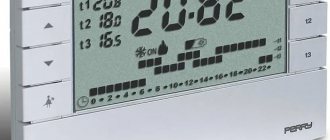
Unlike the BRU, the DBL now has a separate contact cover. This is both good and bad; I will explain this point a little further. The cover indicates almost the same thing as the box - the current, and what size holes there are on the block. Although why the hell should they be indicated in millimeters? You should still indicate the cross-sections - we are not in metalworking, but in electrical engineering. And we work with wires of known cross-sections.
ABB DBL distribution blocks (top cover)
The labeling has changed. Previously, the BRU unit came with stickers with text, but the DBL unit comes with plastic markers. Same as for SNK series terminals. This is good because we can print what we want - for example, if we collect large volumes of panels and we have a printer for printing markers on ABB terminals. And the good thing is that the marker is plastic - it’s not a sticker, whose adhesive part can get dirty or fall off over time.
ABB DBL distribution blocks (complete markings)
The cover of the unit can be opened in either direction (the latches on it are the same on both sides), or it can be removed entirely.
ABB DBL distribution blocks (cover opening)
This is both convenient and inconvenient.
Perhaps here I will describe the difference with BRU blocks. The BRU units did not have a cover, but all the contact block screws were in the back. Sometimes the contact block inside shifted, and it was difficult to get into these screws with a screwdriver. With new DBL units, the cover simply opens the entire contact plate. This is good in that all the screws are immediately accessible, but the bad thing is that it is more dangerous: if the cover is open, then the entire contact block is available for accidental contact.
For example, in a post about the bulkhead of a floor panel in a house of the P-44 series, BRU blocks would be safer than DBL blocks if it was necessary to turn something under voltage:
BRU blocks and their connection to taps for input machines
But... BUT now you can take it, modify the cover (drill holes in the side of the block body and the cover) and SEAL the DBL WHOLE! So you can safely use all sorts of tires for ASU on it. While I was writing the post, I even decided to drill out one block and take a demo photo. Here she is:
Sealing of ABB DBL distribution blocks
I liked the idea! It just turns out that two seals need to be attached so that the lid cannot be opened from either side. But this is MUCH better than shoving such blocks into idiotic boxes for sealing, as I did when I assembled an ASU shield based on the ABB Gemini series. But let the local energy networks fuck with this, since they invent their own idiotic rules.
And the lid can be placed on the block either side. This is done so that the block can be rotated in the shield as desired: either with the large contact down or up:
ABB DBL distribution blocks (any cover position)
The contact part itself is made of tinned brass (on the block on which I tested the seal, I scratched it and saw that it scratched easily, and then it was yellow). In this block, the piece of hardware is fixed with latches along the edges of the case so tightly that I could not remove it from there, and I did not dare to break the case. That is, the lid here covers the contact part, and the part itself is held in the block body. In older BRU units, the hardware was covered with a housing that had holes for screws.
ABB DBL distribution blocks (contact plate)
Actually, that's all. Hm. No =) Here people in the comments asked to also describe the screws. I do:
DBL distribution blocks (screw vs. BRU block)
The screws remain the same as in the BRU blocks, which clamp the cables at the end. That is, such blocks do not and did not have special clamps that do not damage the wire core (as in DIN rail terminals). Therefore, you need to twist either a monocore or a stranded core into the tip here, as usual.
Just in case, I got a couple of articles of these blocks and added them to my database:
- 1SNL308010R0000 ABB DBL80 Cross block 1×8 Cu / Al 80A
- 1SNL312510R0000 ABB DBL125 Cross block 1×8 Cu / Al 125A
Cross-modules: IEK ShNK (first failed since 2010) vs original LeGrand (02.10.2018)
LeGrand cross-modules in the power cabinet
I was once assembling a cabinet for the Radio Center in 2022. So it turned out that there was a lot of interesting and useful things with this cabinet, and therefore several posts are made from it, including an addition about cross-modules.
I assembled the cabinet, the customer had already called the movers... heh, and then I discovered that my favorite cross-modules from IEK had failed me for the first time since ~2010!! Before this, when I had been assembling switchboards using cross-modules from IEK since 2010 (I mentioned this at the beginning of our post), I had not had a single complaint about them for many years... until I started pulling connections in the shield to Radio Center =)
I held it out... and then suddenly I looked - OPANK! And there is a CRACK in the cross-country tire!
Crack in the IEK cross-module bus
And they asked for the shield to be delivered urgently, so we agreed with the customer that he would come, I would show him the shield, in about three hours I would tell him what and how it worked there, and then the loaders would arrive and take the shield. All I had to do was draw the connections and stick the labels on. And then there’s such an ambush!
The movers were canceled, and I began to figure out what to do. Running to the store and changing the marriage doesn’t work. It also turned out that it was the second tire that cracked, and it was on the 4×11 crosses. This means there is a risk of running into a completely defective batch of crosses: they will replace you with a cross from the same batch - and again you will be fucked.
By the way, my statistics are 302 crosses for the entire time of shield assemblies. And not a single marriage, except for this case.
Most likely, they actually received a defective batch. Yes, yes - for the shield in Chertanovo, where the customer was stupid with the purchase of materials, he brought me the same cross:
The customer recently purchased materials and encountered defective cross-modules
But damn! We have three phases in the shield. There, falling off zero is fraught with complete chaos. It means that the time has come to make a tough, fundamental decision: abandon IEC and look for other cross-modules to replace it.
What to look for? ABB is expensive, but stupid, and does not give me the features I need (insulators between buses). All sorts of Tekfor and others are the same China, like IEK. Schneider is the same IEK, only green...
And once upon a time, someone told me that IEC ripped off the design of their cross-modules from LeGrand. And even once upon a time I felt these sneakers with my hands. Well? There is a day or two to make a decision, because the customer needs to connect the cabinet on Wednesday, and at the time the crosses were rejected it was Sunday. Fuck it! We rush to Elektromontazh and start collecting sneakers from all its stores at exorbitant prices (for our own money, of course).
And now I’ll study them properly together with you. Here's what I bought:
New cross-modules from LeGrand after purchase
I'm scared! Imagine, I’ve been assembling everything on IEK for many years, and I’ve already gotten used to them with my hands and head - I know exactly what will fit into which hole, in which place of the shield the cross itself will be pushed, and in which - not. And here everything is new! Oh, creepy!
First we look at the cross from behind. In the original cross-connect everything is the same as in the IEK - it is possible to attach it to the mounting panel with screws or mount it on a DIN rail. LeGrand has much softer plastic, so snapping it onto the DIN rail is a pleasure! IEK sometimes had problems with this.
Rear part of the LeGrand cross-module mount
The second thing that LeGrand did more nicely (and it’s strange that IEK didn’t copy it) is the cross-module cover. Here she is very flexible and pleasant to look at. There are no unnecessary curves, and it closes and opens much easier than the IEK. This can be important in hard-to-reach areas of the shield.
LeGgrand cross-module cover lock
Another convenient thing is that the lid is more transparent, and you can see what’s going on inside the cross-module.
The tires of the cross itself are made of more, ahem, brass: they have a color that is more similar to the color that brass has. Well, that’s what we pay money for, because LeGrand is clear that it costs more than IEK. There are insulators between the buses, which, just like the IEK, will not allow you to insert the wire deeper than necessary and create an interphase short circuit.
LeGrand cross-module busbar screws and insulators
The LeGrand's screw splines are deeper, and the screws themselves are made of stronger steel. Look how shallow the Shurik attachment fits into the IEK screws:
The screws of IEK crosses have shallow slots and the nozzle often falls out
Now compare that to LeGrand. Crap! Well, why couldn’t the Chinese reject such little things? With LeGrand I can safely pull out all the screws with a screwdriver, but with IEK I had to tighten it with a screwdriver.
Deep slot screws for cross modules from LeGrand
LeGrand’s screws are also made so cleverly that if you screw it in, the screw begins to wedge a little from the middle (there is a notch on it for this) and it will never unscrew on its own, even if there is no wire in this hole and the screw is not screwed in all the way . IEK does not have this, and there you have to tighten all unused screws.
OK! Are you happy? Evil tires, harsh screws, can everything be pulled by Shurik?.. Agas! Now let’s add a fly in the ointment. That is, some features of crosses from LeGrand, which will be difficult if, like me, you are switching from IEK.
The first feature is that wires with NShVI lugs of 4..6 squares won’t fit into the outer holes of the farthest bus: the skirt gets in the way. There are no such problems with other tires. My solution is to try not to use these holes, and if I have to, cut off the skirt of the NSHVI.
LeGrand's extreme bus clamps do not accept wires from NShVI
The second feature is that not everywhere there is a place to sign cross-country tires. This applies primarily to 4x7 crosses. The fact is that LeGrand has its own equipment marking system: special U-shaped brackets with numbers and letters that are put on the holders. And crosses have just such holders and are made in the middle of the insulators between the tires.
And if we take a 4x7 cross, then on all tires except the first one, I can stick my inscriptions like this:
It is not very convenient to mark tires on insulators
But near the top tire there is absolutely no room for a sticker - only for a standard LeGrand marker. What should I do if I need to write “L.PEF”? I can’t even write this with standard markers!
I found this solution: stick a sticker on the white protrusion of the cross body. But the photo shows that there is an unevenness there from the casting of the body. So I trim this unevenness with a knife and glue my marker there (in the photo it is simply stuck to the edge of the cross so that it does not get lost).
There is nowhere to mark the upper bus of the 4x7 cross-module
At the same time, large size crosses (4×11 and 4×15) do not have such problems: there the tire insulator is made long, and there is space for stickers and inscriptions everywhere on it.
Large cross-module tire markings (4×11, 4×15)
It’s just these two problems that scared me and made me a little angry. But I successfully solved them and changed the standard for gluing the markings: now I will glue it vertically on all sneakers, edgewise, as you saw in the photos.
Well, now we are facing hellish hell! Replace ALL crosses in the shield with new ones. Why all? Yes, because why do I need inconsistency in a beautiful shield? Since the crosses are all in a row, then we change the entire row.
I marked all the crosses and their tires and made clear inscriptions on the outside:
All cross-modules from LeGrand are ready to replace IEK
And he began to cry, appreciating the scope of work. Here he is:
Cross-modules from IEK in the power cabinet
The shield was already completely assembled, so all the ends of the wires were properly laid and removed. The first cross was difficult - my hands were getting used to the new thing. The second one is easier, the third one is already a blast. It's not so scary: you disconnected all the wires, carefully bent them, removed the cross-connect, put on a new one - and connect again.
We are gradually changing IEC to LeGrand
And this is what I ended up with:
All cross-modules have been replaced with harsh ones from LeGrand and the shield is working successfully
The most evil was the 4x15 cross-module (second from right). There were a LOT of ends there and we had to tinker. But then this fuss paid off in the fact that I easily pulled out all the crosses with a screwdriver, and not manually with a screwdriver!
I was very pleased and quickly, without thinking, in all the calculated panels I changed the crosses to LeGrand's ones in order to completely abandon the IEK crosses. I don’t know if this is true or not, but that’s it. There is no turning back. Now I will use these cross-modules and get used to them. And - I'm used to it! I REALLY liked these crosses!!
Safe cross-module on DIN rail
The use of various twists and screws when distributing wires on the panel is gradually becoming a thing of the past due to its unsafety and inconvenience of work.
Today, a cross-module can be installed in two main ways:
- On DIN rail;
- Using self-tapping screws on the boards.
If it is not possible to install the RB on the mounting rail, you can fasten it with self-tapping screws.
The distribution block is installed between the voltage relay and the meter. If you need to change the distribution of energy among the branches, this can be easily done by changing the arrangement of the cables in the device. The wiring diagram will remain unchanged.