The operation of various modern means of communication is impossible without such devices for receiving and transmitting radio waves as short-wave antennas (abbreviated as HF antennas). The demand and popularity of these devices is due to the wide variety of their types, as well as the possibility of self-production. They are especially common in amateur radio communications with the permitted broadcast range from 1.81 to 29.7 MHz.
Classic HF antenna
Helix antennas
DIY Mimo 4g lte antenna
The classic device of this type (“Tesla Spiral”) consists of two spirals located on crosspieces connected to each other by a jumper (traverse).
Tesla Spiral
Antenna power
Such a device is connected to a transceiver (receiving and transmitting equipment) with a thick coaxial cable with a characteristic impedance of 50-75 Ohms.
Antenna assembly
A small device of this type is assembled by winding two flat spirals with a diameter of 90 cm onto a frame made of polypropylene pipe, consisting of two crosses and a 90-92 cm crossbar connecting them. Single-core insulated copper wire with a diameter of 1.5 mm is used as the material for the spirals.
Transformer
For this device, an air transformer is used with an operating wave range from 10 to 100-160 meters. It is made by winding 16 turns of double wire 1.5 mm thick onto a hollow 140 mm frame with a diameter of 25 mm. The length of the wire winding should be 95-100 mm.
Antenna setup
The setup process includes the following operations:
- Setting the SWR (standing wave ratio) is done using a special device or alligator clips fixed on the vibrator spirals and moved along them, which leads to a change in the position of the power point. The VSC value obtained during tuning at the found frequency should be within 1.0-1.2.
- Adjusting the resonance frequency is done by changing the length of the vibrator wires using the same clamps as in the previous paragraph. The adjustment is made by moving the clamps along the insulated wire of the spirals.
Antenna gain, bandwidth and beam angle
The helical transmitting antenna is placed horizontally at a height equal to 1/8 of the wavelength it emits.
Radio as a hobby
We make an active loop antenna for simple short-wave radio receivers.
Is it possible to listen to the broadcast for people who do not have space to install large, full-size antennas? One of the outputs is an active frame antenna installed directly on the table, near the radio receiver.
The practical production of such an antenna will be discussed in this article...
So, a small-sized active loop antenna is an antenna consisting of one or several turns of copper wire (tube) or even coaxial cable. There are plenty of examples of such antennas on the Internet.
I made my antenna in the form of a vertical structure, which is installed on the table near the radio. An active loop antenna is a sort of large inductor, made of copper wire with a diameter of 1.2 mm and contains four turns. The number of turns was chosen at random)). The diameter of the manufactured loop antenna is approximately 23 cm:
To reduce its own capacitance, the antenna turns are wound in increments of 10 mm. To maintain a constant winding pitch, as well as to give the entire structure the necessary rigidity, intermediate spacers made of 2 mm thick fiberglass laminate are used. A sketch of the spacers is given below:
This is what the intermediate spacer in the antenna looks like:
To give stability to this entire structure, support posts are used, also made of fiberglass, and which serve as antenna legs:
The copper wire is threaded into the corresponding holes in the spacers and posts, and fixed in them with a drop of cyanoacrylate glue.
This is what the stand looks like in a manufactured antenna:
General view of the manufactured antenna:
Just for fun, I connected the manufactured loop antenna to the AA-54 antenna analyzer.
The antenna's own resonance was discovered at a frequency of 14.4 MHz.
In the photo below is the display of the AA-54 antenna analyzer at the moment of measuring the parameters of the loop antenna at the resonance frequency:
As you can see, the antenna impedance at a frequency of 14.4 MHz is 13.5 Ohms, the active resistance is 7.3 Ohms, the reactance is relatively small - minus 11.4 Ohms and is capacitive in nature.
The inductance of the loop antenna (which, in fact, is an inductor) was 7.2 μH.
This is all about the manufacture and parameters of the loop antenna itself.
But, since the antenna is active, it also contains an antenna amplifier.
When choosing an antenna amplifier circuit, I was guided by the principle of choosing something that is not too abstruse and complex, and easy to manufacture.
Google, as always, dumped a mountain of schemes)) Without hesitation, I chose one of them, which seemed interesting to me.
The circuit of this antenna amplifier was published somewhere in the early 2000s in one of the foreign magazines. This amplifier seemed interesting to me from the point of view that it has a balanced input - just suitable for my loop antenna.
Schematic diagram of the antenna amplifier:
In the original, this amplifier used transistors of the BF series - something like BF4**.
There were no such things in stock, so I assembled an amplifier from what was at hand - 2N3904, 2N3906, S9013.
Actually, the amplifier stage is assembled using VT1VT2 transistors. An emitter follower is assembled on transistor VT3 to match the high output impedance of the amplifier with the relatively low input impedance of radio receivers.
The amplifier is powered by a voltage of 6 V. The operating modes of the transistors are set by selecting resistor R3. The voltages at the electrodes of the transistors are indicated in the diagram.
The amplifier started working almost immediately. I tried to install transistors KT315, Kt361 in this amplifier, but its operating efficiency immediately noticeably deteriorated, so I abandoned this option. I assembled the antenna amplifier on a circuit board, but I also prepared a printed circuit board for it:
A direct conversion receiver on a 2TS613B microassembly was chosen as a receiver for full-scale testing of an active loop antenna with an amplifier.
Having connected the output of the antenna amplifier to the input of the receiver and turned on the power, I immediately noticed an increase in the noise level. This is not surprising - the antenna amplifier makes its contribution...
The last stage of testing was to connect the loop antenna itself to the input of the antenna amplifier and try to receive any signals from the air.
And it was a success! Many stations operating with single-sideband modulation on the 40 m range are clearly audible. It is clear that the stations are not heard as loudly as with a full-size antenna. And you cannot compare a normal antenna with a loop antenna located next to the receiver. Also, when operating an active loop antenna, a slightly increased noise level is observed. You have to put up with this - this is the price for small size. It is also advisable to place such an antenna away from all kinds of sources of interference - charging, energy-saving light bulbs, network equipment, etc.
Conclusions : such an antenna has a right to life; it receives quite a lot of stations. For those who do not have the opportunity to hang a large, long antenna, this may be a way out.
Video demonstrating the operation of a loop active antenna on the 7 MHz band:
Magnetic antennas
DIY digital TV antenna
The most common HF antenna design is a magnetic loop , consisting of:
- Duralumin or copper radiating ring with a diameter of 25-80 cm;
- Communication loops, the diameter of which is 5 times smaller than that of the radiating ring;
- Supply cable (feeder) with a characteristic impedance of 50 Ohms;
- A powerful capacitor adjusts the resonant frequency.
Magnetic frame loop
Such simple homemade transmitting devices are installed both on high masts, roofs of high-rise buildings, and on balconies or window sills of apartments. Thanks to a tuning capacitor capable of operating at a power of up to 100 W, such amateur radio shortwave antennas operate in the range from 1.8 to 27 MHz.
SIMPLE HF ANTENNAS
V. BASHKATOV, USOIZ, Gorlovka, Donetsk region.
Multi-band dipole The design of this antenna was told to me over the air about 10...15 years ago by radio amateur V. Voliy (UA6DL), for which I am very grateful to him. The antenna still works, and I am, in principle, satisfied with its performance as a backup antenna. The measured SWR values for a frequency of 1.9 MHz are 1.9; for 3.6 MHz - 1.3; for 7.05 MHz-1.2; for 14.1 MHz -1.4; for 21.2 MHz -1.7; for 28.6 MHz - 1.6. The antenna design is shown in Fig. 1. The antenna is an ordinary dipole with a beam length of 20.5 m. The antenna is powered by a coaxial cable with a characteristic impedance of 50...75 Ohms. For matching, a broadband matching device on a ferrite ring and a two-wire line with a characteristic impedance of 300 Ohms are used. The two-wire line is made of a 17.7 m long CATV television cable, open at the end. The broadband transformer is made on a ferrite ring of grade 30...50 HF with an outer diameter of 24...32 mm - depending on the transmitted power (1 cm of the cross-section of the ring core is capable of transmitting about 500 W without damage). If one ring is not enough, take two or three rings folded together. The ring(s) are pre-wrapped with fluoroplastic tape. At maximum power, the ring can heat up to 70°C. The transformation ratio of the broadband transformer is 1:4. To make a transformer, a PEV 00.8...1.0 wire folded in parallel or a stranded wire in vinyl or fluoroplastic insulation (not afraid of heating) is wound around the ring. The number of turns is 9…10. After winding, the end of one wire is connected to the beginning of the other, forming a midpoint. The broadband transformer is mounted at a distance of 5.9 m from the point where the dipole is connected to the two-wire line. The transformer is protected from moisture by wrapping it with insulating material and varnishing it. The antenna fabric is made of galvanized wire dia. 2 mm, and, apparently, that’s the only reason it stood for such a long time in the acid rain conditions of Donbass.Rice. 1
In principle, the antenna arms can be made from 5...8 twisted copper wires of PEV grade 0.8 mm. Tested - good strength. Horizontal wire wave channel. As amateur radio wisdom says, the best high-frequency amplifier in a transceiver (receiver) is an antenna. And this is 100% true! Having a good antenna, you can even work with a homemade transceiver with DX, and vice versa, you cannot “pull out” the same high-frequency correspondents with “weak” correspondents with an expensive imported transceiver and a bad antenna. Directional antennas are widely used for these purposes, since they make it possible to concentrate most of the emitted electromagnetic energy in a certain direction, thereby increasing the field strength at the receiving location and reducing interference in other directions, as well as receiving a higher signal level when receiving from this direction. Of course, the best option is to install a rotating directional antenna, but not all shortwave operators can afford to purchase and install such an antenna.
Fig.2
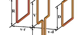
I propose the design of a compromise version of a single-band two-element “Wave Channel” antenna (Fig. 2) with a fixed radiation pattern. The antenna is located in a horizontal plane and has clearly defined directional properties. The design of the antenna is clear from the figure. In this antenna, one active vibrator is a half-wave dipole, the second passive vibrator is the director. The current in a passive vibrator is created due to electromagnetic induction by the field of the active vibrator. By changing the length of the passive vibrator and its distance from the active vibrator, you can change the relative phase of the current in it. This is the basis of the principle of concentration of electromagnetic energy in a certain direction. If the phase of the current in a passive vibrator is such that the resulting field in the direction of this vibrator increases, and in the opposite direction it decreases, the passive vibrator works as a director. Such an antenna provides a power gain of about 5 dB. The attenuation of interference from radio stations located perpendicularly and behind the direction towards the correspondent is also significant, which for this antenna is approximately 15 dB. An antenna made according to the given dimensions, as a rule, does not need to adjust the length of the elements and the distance between them. The antenna fabric is made of copper rope, copper, galvanized or bimmetallic wire, dia. 2 mm. If such wire is not available, you can make a homemade copper rope from 6...8 PEV-I or PEV-II 0.7...0.8 mm wires twisted in increments of 2-3 turns per 1 cm. The ends of the rope should be well soldered. This homemade wire rope is quite durable. Naturally, before installing this antenna, the radio amateur must determine for himself the most interesting direction of radiation (reception). The design dimensions of the antenna for each range are given in Table 1.
Range, m Director length (D),M Vibrator length (W),M Distance WD, m 20 9,73 10,34 2.13 17 7.56 8,08 1,65 15 6,48 6,87 1.42 12 5,49 5,87 1,20 10 4,80 5,11 1.06 The antenna fabric itself is attached to stationary supports using a nylon (synthetic) cord, which can be buildings, residential buildings, tall trees, etc. Porcelain nut insulators are used as insulators. However, if such insulators cannot be purchased, they can be successfully replaced by homemade insulators made from textolite or getinax. To make them, take an insulating block (parallelepiped made of textolite, getinax, etc.) of suitable dimensions, and two holes are drilled in it along the diameter of the wire at an angle of 90°. Homemade insulators must work in compression. Insulation strips made of bamboo (pine, getinax or textolite) serve as distance clamps (spacers) between the director and the active element. All cord connections are made only with viscous knots. To protect against moisture, insulators and spacers are coated with insulating varnish. The design of these insulators is shown in Fig. 3.
Rice. 3
Simple effective antenna G3XAP for 160 and 80 m Long-distance communication on short waves is carried out due to the so-called sky wave, which is reflected by the ionosphere and can have both vertical and horizontal polarization.
When operating on the 160 and 80 m bands, shortwave radio amateurs use both ground waves and sky waves. That is why it is desirable for this range to have an antenna with vertical radiation. Since a vertical quarter-wave vibrator for the 160 m range is difficult to imagine even in the imagination (its height should be about 40 m!), the antenna for low-frequency ranges has to be made as a compromise. Its emitter consists of horizontal and vertical conductors (Fig. 4), or the emitter is placed at an angle to the horizon.
Rice. 4
Naturally, the greater the height of the vertical part of the antenna, the higher its efficiency. In addition, the efficiency of a vertical U4 antenna largely depends on the quality of the grounding. It is best to use special grounding - a pin driven into damp ground, a buried sheet of galvanized iron, etc. As a last resort, you can use metal structures fixed in the ground. It is unacceptable to use water supply and heating pipes as such grounding, because In addition to the poor quality of such grounding, severe interference with radio and television reception is possible, as well as burns from high-frequency currents for people who touch the pipelines. The proposed antenna was repeated by Yuri in the late 80s, US31VZ, ex RB41VZ. Actively operating SSB on the 160m band, in one year he received QSL from 150 regions of the former USSR. US3IVZ uses this antenna without counterweights. For more efficient operation, it must have counterweights. A 2-inch diameter steel pipe is mounted on a small support insulator, which can be used as porcelain insulator used in electrical installations, or simply by placing a sheet of insulating material under the vertical pipe. To tune the antenna, use a variable capacitor C^^=500 pF, which has a gap between the plates of at least 1...2 mm (depending on the power of the PA). The quality of matching is judged by the readings of the SWR meter. The input impedance of such an antenna is approximately 60 Ohms (depending on the quality of the ground), so it is advisable to power it with a coaxial cable with a characteristic impedance of 50 Ohms. With careful tuning of the antenna, we can achieve SWR = 1.1...1.2. The antenna dimensions are given in Table 2.
Range, m L1, m L2, m 160 14,6 37,5 80 7.3 19,8 Literature
1. S.G.Bunin, L.P.Yaylenko. Shortwave Radio Amateur's Handbook. - Kyiv, “Technology”, 1984.
Radiomir. HF VHF. 10/2001, pp.33-35.
Capacitive antennas
Multiband antenna
A multi-band antenna is a device that allows broadcasting in all short wave bands permitted for amateurs. Thanks to this property, multi-bands have become very popular and widespread.
One of the UA1DZ type multi-bands has the following design:
- Vibrator 9.3 m long
- 3-meter stand;
- 4-5 quickdraws;
- 10-14 additional flexible counterweights, 9.4 m long.
The connection of such antennas and transmitters is made using a 50 Ohm coaxial cable.
The main disadvantages of such multi-band structures are their bulkiness, high windage and the risk of lightning when installed on the roof of a high-rise building or other multi-story building.
Vertical Antenna (Ground Plane)
Vertical Ground Plane antennas are devices designed for broadcasting in the ranges from 14 to 24-28 MHz. The main components of such vertical HF antennas are a 2-meter mast, a duralumin vibrator 2 to 5 meters long, 4-5 counterweights 2.5-3 meters long and a 50-ohm coaxial supply cable.
They are installed both on the roofs of high-rise buildings and on the gables of private houses.
Short dipole antenna
The simplest device of this type at 7 MHz is a structure consisting of the following parts:
- A wire vibrator divided into two 3-meter arms with insulators and guys at the ends. Small pieces of textolite are used as insulators; durable nylon linen cord is used for guy ropes.
- Two extension 140-turn coils made of copper wire 0.5-0.6 mm thick;
- Central unit with transformer (balun);
- Feeder – 50 Ohm supply coaxial cable.
Short dipole
Such a shortened dipole is used both in stationary and field conditions, fixing it at a height of 3 to 4 meters.
On a note. In order to tune such a device for resonance, it is necessary to uniformly shorten the length of the horizontal or angled arms of the vibrator. After changing the length of the arm, the guy that shortens it is attached to the nearest tree or other stable support.
Notes from a programmer
After working on the air for a while, and reading about propagation, antennas, matching devices and such, I had a better idea of what I needed from an antenna. It was decided, taking into account the accumulated knowledge and experience, to make a new antenna that would better suit my current limitations and interests. I also wanted to get the cheapest and simplest antenna possible so that other beginning radio amateurs could replicate it.
Formulation of the problem
Lately I've been using a multi-band delta. The antenna served me faithfully for more than a year, providing access to all HF bands from 10 to 40 meters, and, with a noticeable loss of efficiency, even to 80 meters. Many QSOs were made across a variety of modes, including a number of intercontinental ones, all with good reports. Overall, it turned out to be a normal antenna.
So what are her problems:
- The lower part of the antenna sheet is at the level of human height. That is, relatives or neighbors may be located almost close to the antenna. In the daytime, you have to either constantly look out the window or work on a transmission with reduced power;
- The antenna is located close to the house, and therefore has a high noise level and collects sudden impulse noise. The difference compared to a dipole located 10 meters from the same house is noticeable to the naked eye;
- The radiation pattern and polarization of the antenna on each band is not very clear. The simulation results disagree with the observed data, the same input resistance. I would like to have a rough idea of which direction the signal is going and with what amplification;
- Unknown losses in the matching device and 1:4 balun. The video How much power is your QRP antenna coupler losing by Peter Parker, VK3YE, clearly demonstrates that typical losses in a matching device can be on the order of 1 dB, or 20% of the power;
- To change the range you have to turn the knobs. This problem can be solved using the mAT-30 autotuner. But then the antenna will be tied to a limited number of transceivers compatible with it, which I would like to avoid. In addition, the auto tuner is extra wires. Also, let me remind you that when using this autotuner, the Yaesu FT-891 reduces the output power in proportion to the SWR;
- The antenna bandwidth could be wider. In winter, the antenna can bend under the weight of snow, causing the input impedance to change. As a result, a newly matched antenna may become unmatched after ten minutes. Appears only during snowfall;
- The antenna was made of P-274M wire. This is a fairly thick black wire. I would like the antenna to be less conspicuous. So, just in case;
- It feels like I've worked with almost everyone I could with this antenna. It is quite rare to find new correspondents. It is worth saying that now I am most interested in working in the telegraph office, and sometimes in SSB. There are enough new correspondents in FT8, but I’m not very interested in working there;
According to the magazine, 75% of radio communications during my entire time on the air were carried out in the ranges of 20 and 40 meters. I was ready to sacrifice the rest of the ranges, leaving only the two most often used by me in practice. To access other bands, I can always deploy some kind of temporary antenna.
Preparatory work
There are not so many simple and at the same time effective antennas - these are a dipole, a vertical and a loop antenna. I don’t have space for two independent antennas, so I need one antenna for two bands. It is possible to make a multi-band frame, but it is quite troublesome. The vertical, so that people don’t walk near it, needs to be placed on the roof. The roof of the house is metal, which is good for vertical. But I don't want to climb onto the roof in the middle of winter in case something happens to the antenna. Thus, a dipole remains.
A multi-band dipole can be made using either two pairs of arms, ladders, or a 1:4 balun. I settled on the first option because it is the simplest. It was decided to power the antenna using an RG-213 cable, since this produces small and known losses, and the cable can be used of any convenient length. Thus, it was necessary to make a 1:1 current balun.
The last time I made a balun it was heavy and expensive because I used a FT240-31 ferrite ring. It was decided to wind the balun on a cheaper and lighter ring with a similar initial magnetic permeability, and see what happens. For the ring I chose M1500NM3, 45x28x12. The ring is large enough to wrap an RG-58 cable around it. But I wanted to use bifilar winding, simply because I had never used it in baluns before.
The following photo shows the balun itself and how the dependence of the winding impedance on frequency was measured:
The impedance, as well as the SWR at an equivalent load of 50 Ohms, turned out to be as follows:
A graph similar to the first one, only for the FT240-31 ring, was previously presented in the post Antenna Analyzer FAA-450 (EU1KY). It can be seen that the M1500NM3 copes worse. However, at frequencies from 1 MHz to 14 MHz we see an active resistance of more than 500 ohms, which means the balun does a good job of suppressing common mode currents. I note that if you use RG-58 cable instead of a bifilar winding, the graph will be the same.
I was much more worried about the SWR. It can be seen that at 14 MHz the balun begins to introduce significant reactivity. The working version was that this reactivity would be compensated by the length of the arms of the antenna itself. The balun was also tested at an equivalent load when delivering a carrier power of 100 W. Nothing in the balun overheats anywhere. This indicates that the balun is working correctly.
The final look of the balloon turned out like this:
I noticed that a PVC pipe with a diameter of 20 mm is ideally inserted into the wound ring. I used it as a frame. An SO-239 connector is inserted into the tube from below, and a loop is attached to the top. The loop was cut from the grill grate using tin snips. The grate was bought new and turned out to be too small for the grill, so it lay idle. With the same success, you can use thick copper wire or any other available materials. Everything is held on with epoxy glue.
As an experiment, an inverted-V antenna was made for the most difficult range for a balun, 20 meters. The antenna was raised on a telescopic rod to a height of 7 meters. I made the lengths of the arms exactly 5 meters, and on the first attempt I got almost where I needed them:
It looks as if the theory of reactivity compensation is being confirmed. Several test radio communications were carried out on both CW and SSB. They all went through without problems. This way I made sure that the balun works as it should even in the 20 meter range.
Final decision
This is what a two-band antenna looks like:
SWR charts:
The results are similar to those obtained when making a fan dipole from a two-wire line. This time the arms were located almost in the same plane, which did not greatly affect the properties of the antenna. Interestingly, the SWR graph on the 20 meter band can be manipulated by adjusting the distance between the arms from the ground. The closer the arms are to each other, the lower the frequency the resonance will be at 20 meters. This time it was not possible to get “bonus” ranges. On bands other than 20 and 40 meters, the SWR does not fall below 5.
Unlike the previous version of the antenna, here we have significantly lower losses in the power line. In addition, the line can be of any length. The wires and fishing line used were the same as last time. This makes the antenna not very noticeable against the sky. Closer to the ground, the fishing line was covered with electrical tape. This is done to prevent anyone from accidentally bumping into it. Insulating tape also gives the fishing line additional protection from friction against the fence in case of strong winds.
I made a little mistake with the choice of mast. A 20 meter long telescopic fishing rod was purchased on eBay. I hoped that I could use 15 meters for the mast. But it turned out that in this case you need at least two tiers of guys, otherwise the mast bends too much in the wind. And my relatives are not enthusiastic about the idea of stringing ropes all over the yard. As a result, the height had to be limited to 10 meters, and the fishing rod had to be secured only at the base, tied to the fence. From past experience, I know that this design can withstand any strong wind, even when using much thinner rods.
To prevent the rod sections from collapsing in the wind, I secured them with reinforced tape. To prevent the tape from peeling off over time and to prevent water from flowing under it, it was coated with Plastik 71 varnish on top. The insulation of the junction of the coaxial cable with the balun is made according to the same principle, only instead of reinforced tape, several layers of electrical tape are used.
Important! Do not use spray varnish. If the wind blows unfavorably, the varnish will get into your eyes or people passing nearby.
Ten meters is a very good height for inverted-V on the 20 meter range. The antenna is well suited for long-distance communications. For the 40 meter range the height is λ/4. The radiation pattern leaves much to be desired. Many radio amateurs will say that such an antenna is not good for anything at all, since it “radiates to the zenith.” But I'll venture to argue.
Firstly, even if so, we already have an antenna for long-distance communications. Why not configure the second one to be better suited for short-range communications? Secondly, in fact, even at this height, the antenna can compete in gain at angles of 20-30 degrees with the vertical:
The real problem is not the amplification itself, but the fact that signals from distant stations can be blocked by signals from nearby ones. But if we are talking about the telegraph, then two stations simultaneously using the same frequency is a rare phenomenon. The telephone is still not the best type of communication for DX.
Thirdly, the book Propagation and Radio Science by Eric Nichols, KL7AJ convincingly shows that radio waves do not literally reflect from the surface of the earth. In fact, radio waves penetrate underground, and much deeper than is commonly thought. Thus the “reflection” occurs underground. As a result, the low-hanging inverted-V performs better than it should because its effective height from the ground is greater.
Important! Be sure to use an ESD choke with this antenna. The inductor must be properly grounded.
Test results using WSPR at 5 W are encouraging:
Here we see that my signal was received basically all over the world, both on 20 meters and 40 meters.
Indeed, it is often possible to make long-distance communications with this antenna. Japan (7500 km) and the USA (8600 km) are still leading in the range of 20 meters in distance. In the 40 meter range, I was able to make QSOs with radio amateurs from Brazil (12,100 km), Australia (12,500 km), and also New Zealand (16,150 km). It happened during the context of CQ WPX CW 2022. All radio communications are in the telegraph.
This is an interesting result. Although it would seem that the antenna pattern at 20 meters is better and the noise level in this range is much lower. UPD: Later, no less long-distance communications were carried out in the range of 20 meters than in the range of 40 meters.
Conclusion
The result was just a normal antenna, devoid of all the shortcomings mentioned at the beginning of the article. I've been using it for one month. The mast holds up, the fishing line doesn’t break, and the neighbors don’t complain. The antenna is recommended for repetition and use by beginner shortwave operators.
If after reading the article you still have questions, do not hesitate to ask them in the comments. It would also be interesting to know in which amateur radio bands you usually work, what antenna you use as your main one, and what kind of radio communications you can make.
Addition: Refinement of the antenna is described in the posts Experiments with ladders of various designs and Ladder dipole for 10/20/40/80 meters.
Tags: Antennas, Wireless, Ham Radio.
DIY vertical HF antenna
The most popular for DIY production are short-wave transmitting devices such as vertical antennas.
The simplest and most effective of them is done as follows:
- A wooden column 2.5-3 meters high is dug into the ground;
- The distribution box is secured to the buried post using self-tapping screws;
- A high-frequency choke is placed in a fixed box - a coil with turns of insulated coaxial cable wound on it;
- A two-core stranded copper cable with a cross-section of 2 mm is connected to the inductor output;
- The wire is threaded through the guide rings of a cheap 6-meter carbon fiber rod;
- The end of the wire is secured to the tip of the rod using a regular plastic tie;
- A round platform with guy wires is fixed in the middle of the rod;
- On the top of the post, 2 clips and one clamp holder (KTR) for polypropylene pipes with a diameter of 32 mm are attached;
- Using clips and a holder, the rod with the emitter (wire threaded through the guide rings) is secured to the pole;
- Using guys, the mast with the emitter is leveled and securely fixed. Guys are secured to stable, nearby poles, trees, and hooks screwed into the supporting structures of buildings and permanent structures.
The supply wire for HF antennas of this type is used with a characteristic impedance of 50 Ohms.
Maintenance of such a device comes down to periodically checking the integrity of the emitter by testing it with a multimeter, replacing mast knees broken by the wind, and adjusting the tension of the guys.
Dipole antenna on CB
What could be simpler than a dipole? Probably nothing. This is the easiest antenna to manufacture available to most radio amateurs. It's easy to calculate, easy to manufacture, easy to configure and even easier to use. It turned out that I didn’t have any antenna in the magazine’s laboratory for about a year, and recently I decided that I had enough of putting up with it!
In this article I will tell you how to calculate, from what and how to make a simple 27 MHz dipole antenna. I will show you the entire process of building the antenna, from the idea to the finished product. The antenna was designed with the expectation of long-term maintenance-free operation and therefore much attention was paid to protection from the harmful effects of the atmosphere. In addition, the correct dipole must be powered through a balun. What it is and what it is eaten with, read below.
Technical task
The conditions in which the antenna is supposed to be used are not the most favorable. Roof of a two-story building. Not a dominant height. There are not many high-rise buildings around, but they exist. Soft roof. We are limited in our maneuver from the point of view that it is problematic to get onto the roof without authorization, fixing antennas above the roof level is also quite difficult, there are no structures for this, and no one will allow new ones to be built. The only thing they allowed was to drive a hook into the wall above the window, and thank you for that. In general, one cannot count on a great range of such an antenna, just based on the placement conditions. In addition, the antenna should not interfere with anyone’s use of the roof. All sorts of organizations often come to the roof to monitor the condition of the roof and air conditioners and other equipment. In short, the conditions suck, but I still want an antenna. Therefore, the simplest option was chosen - a dipole.
What is a dipole
A dipole is a symmetrical vibrator, the simplest and most common antenna in practice. In its simplest form, it is a straight conductor half a wavelength long and fed in the middle from a generator with high-frequency currents. In other words, these are two identical pieces of wire stretched in space in series, one after the other. But in the center of this structure, the point of their connection, a cable is connected to them, through which the signal will go from the dipole to the transceiver and from the transceiver to the dipole. It's simple. The dipole can be either vertical or horizontal. In this case, the polarization of the waves received and emitted by such an antenna will change according to the orientation of the dipole. Vertical dipole – vertical polarization (suitable for local communications), horizontal dipole (suitable for long-distance communications). A dipole stretched at an angle has both components.
Project and calculation
Before picking up tools and starting to do something, it would be a good idea to calculate what size dipole we need, in addition, this will help us calculate the amount of wire that we will use for the dipole beams. You need to understand that the actual (geometric) length of the dipole is somewhat less than that calculated by the formula. This is due to the fact that a capacitive current appears at the ends of the antenna, which is equivalent to an increase in its length. The required length of the dipole, taking into account the corresponding shortening coefficient, can be calculated using all sorts of clever formulas, which I will not give, but we can use more technologically advanced means and involve the MMANA modeler program in our creativity. And if you, being a radio amateur, for some reason still have not mastered it, I strongly recommend that you do so. For the design and calculation of simple antennas, this is an absolutely indispensable tool.
So our project looks like this. Antenna dipole. The top point of suspension is at a height of 3 m, the center is at 2.5 m, the bottom point is at 2 m. Not a lot, taking into account the fact that the SWR and operating parameters of a dipole-type antenna in general depend quite strongly on the height of the suspension, but there is not much to choose from. The length of the antenna arms is approximately 2.57 m, the wire diameter is 2 mm (R = 1 mm).
We enter this data into the modeler and get the following.
We calculate the parameters for the frequency 27.200 MHz. Center frequency of the central grid.
This seems to be true, given that the dipole in free space has a resistance of about 75 Ohms, which corresponds to SWR = 1.5. I'm quite happy with this.
SWR, as well as the active and reactive components of the impedance. The parameters for our antenna are quite suitable.
Directional pattern. The antenna with this placement will mostly receive anti-aircraft radiation. This is a consequence of the low suspension, but nothing can be done about it.
We will power the antenna not just through a coaxial cable, but through a balancing device (balun). A balun is a balun transformer. It is called so because of the use of abbreviated Anglicisms in the name. Balanced-Unbalanced. Or Balun. (BalUn). It is necessary to power a symmetrical antenna. The dipole is just a symmetrical antenna, but it will be powered by an unsymmetrical line, which is a coaxial cable. But more about the balun below. So, having approximately estimated what awaits us, we can begin production.
Constructive
For the lazy and those who just want to try to make such an antenna, there is an easier option. I’ll immediately give you a picture borrowed from EU4DGC. I won’t comment separately, everything is clear on it. Repeat and it will work.
But since the reliability of the design was not the least important thing for me, I decided to approach the matter more thoroughly. To make a dipole, we first need to make a blank for a dipole-type antenna. This thing is necessary for the full implementation of the balun. You, of course, can buy a ready-made balloon, but, in my opinion, making it yourself is easier, cheaper and more interesting.
For construction we will need.
1. Plumbing plastic coupling with a diameter of 50-55mm. Sold in plumbing stores. 2. Plumbing plugs of the same diameter. Sold there. 3. Connector type SO-239 4. Ring screw 3 pieces (M6). 5. 6 washers and 3 nuts.
Let's start preparing. We drill holes in the plug caps and coupling.
In the coupling of one of the plugs there is a diameter of 6mm, for fastening, and 16mm in the other, for the connector. We drill holes under the fastenings and for the output of wires with which we will feed the antenna beams.
We install the fasteners. When assembled, the structure looks like this.
Now let's start making the balun.
Balun
As I wrote above, a balun is a balancing device that allows you to get rid of the antenna effect of the feeder. If this is not done, our down cable will become a full part of the antenna and, when receiving, will work as part of the antenna, collect signals, interference and noise, and radiate when transmitting. We don’t need this at all, so we will make a balancing device on a ferrite ring. As we remember, our dipole resistance is about 75 Ohm, which means that for proper matching of the antenna, our balun should not transform the resistance, but should simply transmit the signal 1 to 1. The simplest version of the balun is shown in the figure below. It is made on a ferrite ring with a trifilar winding.
To make such a balun, we need a ferrite ring, I found one with a permeability of 600, a piece of wire with a cross-section of 0.5-1 mm, and in the bins I found a piece of MGTF with a cross-section of 1 mm and a length of 2.5 m.
We fold the wire in three and begin to wind it around the ring. In the end we should end up with something like this.
We fix the winding on the ring using clamps or electrical tape and begin connecting the windings in the required sequence. Ready option.
We mount the balun into our blank. And solder the connector.
We put everything together and in the end we should have a design like this.
Almost done. Now we need to measure the required amount of wire for the antenna beams and attach them to our, now blank, balun. For the beams, you can use almost any wire of sufficient thickness; I usually use a regular PV with a cross-section of 1.5 mm^2. We measure out 3 meters, despite the fact that MMANA calculated us 2.57 m, it is better to take it with a reserve and then cut off the excess than to frantically figure out how to build up what is missing. Plus, part of the wire will be used to attach the beams to the balun and guys. We screw the beams to the ears of the balun and connect the leads of our balun to the beams.
After this, we solder everything well. Actually, the antenna itself is ready.
All that remains is to figure out what to make the guy wires out of. Personally, I prefer to use regular paracord for these purposes. It is strong, reliable and does not stretch much under load.
It's time to climb onto the roof and install the antenna. I won’t post the whole process, but I’ll go through the main points.
Upper antenna mounting point. There is a hook anchor screwed into the wall.
The antenna itself and the reduction cable. The cable is a regular RG-58 C/U with a length from the power point to the radio station of approximately 15 m. The cable length does not affect the antenna tuning.
Antenna setup
Since the dipole is a symmetrical antenna, the length of the antenna arms must be the same! I recommend starting with the length that MMANA gave us; as a rule, starting with this we can with a high probability get exactly where we need. There is no need to cut off the antenna sheet; just bend the excess part parallel to the antenna sheet and wrap it with electrical tape or secure it with a cable tie. To fine-tune, you may have to remove and re-tension the antenna several times, adjusting the length of the arms to the frequency you need. This is what I ended up with.
At SWR=3, the dipole has a bandwidth of almost 5 MHz, at SWR=2 almost 2.5 MHz.
Active and reactive components.
In my opinion, everything is not bad.
Bottom line
The result was a fairly universal and, most importantly, simple antenna for the CB range. In my case, it is not located in the best way, but, nevertheless, it is quite functional. The receiving and transmitting may not be as long as a 5/8 vertical, but, in my opinion, it is much better than nothing at all. This structure can be assembled with all the necessary parts in an hour and a half, very quickly. This antenna has been hanging outside the window for only a few days, testing continues, so far I am quite happy with the result, if there are any additions, I will definitely write about them. Well, or if someone decides to repeat my feat, I would be glad to have fresh opinions and comments.
Good luck to everyone, 55, 73!
Selecting the first HF transceiver
When choosing the first transmitting device (transceiver), novice radio amateurs need to consider:
- Dimensions and weight - the radio station must have such dimensions and weight that it can be easily carried in hands or in a backpack.
- Functionality - for a beginning radio amateur, a transceiver with a small number of basic settings (resonant frequency, power, SWR) is sufficient;
- Reliability and warranty - like any other equipment, a shortwave radio station must have a warranty period;
- Possibility of programming equipment using a personal computer.
Transceiver
Beginner radio amateurs are not recommended to purchase expensive shortwave radio stations that are very difficult to operate and maintain. It will be very difficult for a beginner who is interested in amateur radio to understand such equipment; if they lose interest in this matter, selling such an expensive radio station for the same amount as it was purchased will be very difficult.
About the antenna asymmetrical dipole from UB9JAF
About the antenna asymmetrical dipole from
UB 9 JAF .
Every radio amateur faces the problem of choosing an antenna.
The question of choosing an antenna is multifaceted, since various factors are intertwined in it, the main ones being economic, technical and geographical. A radio amateur has to work hard to bring these factors together on one plane.
The problem is that an antenna with high technical parameters is usually large in size and requires significant material costs, as well as space for its location.
Great difficulties arise when choosing antennas for low-frequency ranges, since in these ranges the antennas are large in size and corresponding costs are required to create an effective antenna.
It takes radio amateurs many years to create an effective antenna system.
It is especially difficult for radio amateurs who have changed their place of residence and are temporarily left without an antenna, as well as for those who are just starting to work on the air.
In this case, you can pay attention to multi-band simple antennas that do not require large material costs, but allow you to start working on the air in a short time.
One such multi-band antenna is a single-ended dipole.
The antenna received multi-band properties as a result of the displacement of the feed point, which allowed it to be called asymmetrical.
You can consider the features of the method of feeding the antenna using the graph presented in Fig. 1.
The graph shows the dependence of the input impedance of an antenna 21 meters long on various amateur radio bands.
At point “A” the value of the input impedance for the ranges 7 MHz, 14 MHz, and 28 MHz has the same value and is 240 ohms.
By connecting a 1:4 matching transformer and a 50 ohm feed line to this point, you can get a simple tri-band antenna.
For the 21 MHz range, point “A” corresponds to a resistance value of 3000 ohms, so on this range the option with a 1:4 transformer will not work.
On the 3.5 MHz band, the antenna at point “A” has a resistance value of 240 ohms, and at a length of 21 meters, that is, at the end of the antenna its resistance is 60 ohms, but should be 3000 ohms, so the antenna will not work on this range either .
However, if the antenna width is increased to 42 meters, then you can get a four-band version of an asymmetrical dipole, 3.5 MHz, 7 MHz, 14 MHz, 28 MHz.
Next, we will talk about the design of a four-band asymmetrical dipole from the Nizhnevartovsk radio amateur UB9JAF.
A photograph of the antenna is shown in Fig. 2.
Fig.2.
The antenna is made of two pieces of insulated copper wire with a diameter of 2.3 mm.
The insulators are made of fiberglass. The insulator has a thickness of 8 mm, length of 10 cm, width of 5 cm.
The central insulator has dimensions of 10 by 8 cm; a matching transformer is attached to the central insulator.
A photograph of the matching transformer is shown in Fig. 3.
Fig.3.
The matching transformer is made on the HF 65-40-9 ring.
The transformer windings are made of insulated single-core wire with a diameter of 1.78 mm and contain 17 turns. The transformer was wound in two wires. The winding connection diagram is classic, the end of one winding is connected to the beginning of the other.
After manufacturing the transformer, it was configured using the MFJ-269 device. The setup was carried out according to the standard method presented in the technical description of the device.
During the setup process, the transformer was loaded to an active resistance of 200 ohms, then the SWR value was measured on all amateur bands, then the number of transformer turns was changed, depending on the SWR value, the number of transformer turns was changed up or down.
After setting the SWR of the transformer was:
3.5 - 10 MHz SWR 1.1;
10 – 20 MHz SWR 1.3;
20 - 30 MHz SWR 2.2.
After setting up, the transformer was placed in a polyethylene cup (Fig. 4). and filled with epoxy resin. The threaded connection intended for attaching the transformer to the central insulator is made of polyethylene.
Fig.4.
During the design of the antenna, the length of its arms was adjusted. The adjustment was made according to the minimum SWR values,
using the MFJ-269 device.
During the setup process, the antenna was raised onto the masts using blocks, the SWR was measured, then the antenna was lowered, then the antenna arms were lengthened or shortened and the SWR was measured again.
The results of the experiments are presented in tables 1-4.
Table 1.
| Shoulder length 13.3 +27.7 meters | |||
| Range | R | X | SWR |
| 3,550 | 60 | 0 | 1,3 |
| 3,650 | 49 | 0 | 1,1 |
| 7,1 | 63 | 18 | 1,7 |
| 14,15 | 44 | 17 | 1,5 |
| 28,5 | 36 | 13 | 1,5 |
Table 2.
| Arm length 13.3+27.55 meters | |||
| Range | R | X | SWR |
| 3,550 | 62 | 0 | 1,5 |
| 3,650 | 100 | 0 | 1,9 |
| 7,1 | 81 | 13 | 1,7 |
| 14,15 | 58 | 33 | 1,9 |
| 28,5 | 31 | 15 | 1,8 |
Table 3.
| Shoulder length 13.3+27.75 meters | |||
| Range | R | X | SWR |
| 3,550 | 80 | 0 | 1,5 |
| 3,650 | 100 | 11 | 1,9 |
| 7,1 | 58 | 0 | 1,1 |
| 14,15 | 49 | 0 | 1,1 |
| 28,5 | 38 | 0 | 1,3 |
Table 4.
| Arm length 13.2+27.75 meters | |||
| Range | R | X | SWR |
| 3,550 | 50 | 0 | 1,0 |
| 3,650 | 63 | 0 | 1,3 |
| 7,1 | 65 | 0 | 1,1 |
| 14,15 | 55 | 0 | 1,0 |
| 28,5 | 49 | 0 | 1,3 |
As a result of the adjustment, the option of arm lengths presented in Table 4 was selected.
Then the experiments were continued, and a broadband transformer was manufactured according to the recommendations proposed in the Radiodesign magazine,
The transformer circuit is shown in Fig. 5.
Fig.5.
The measurement data of the SWR of the transformer, made according to the circuit in Fig. 5, is presented in Table 6.
Table 6.
| Frequency, MHz | 1,76-6,8 | 6,8-11,3 | 11,3-13,75 | 13,75-14,76 | 28,0-30,0 |
| SWR | 1,0 | 1,1 | 1,3 | 1,4 | 1,3 |
Photo of the transformer Fig. 6.
Fig.6.
As a result of using this transformer, the following antenna SWR values were obtained, Table 7.
Table 7.
| Length 13.3 +27.7 meters | |||
| Range | R | X | SWR |
| 3,579-3,797 | 57 | 0 | 1,7 |
| 7,04 – 7,2 | 49 | 0 | 1,5-1,4 |
| 14,100 – 14,350 | 61 | 0 | 1,3-1,1 |
| 28,010 -28,595 | 41 | 3 | 1,1-1,5 |
Photo of the antenna Fig.7.
Fig.7.
Nizhnevartovsk 2010
Get text
Other antenna designs
Among other HF antenna designs, the vertical spiral half-wave vibrator for waves 80 meters long, consisting of:
- 120-centimeter spiral made of insulated copper wire with a diameter of 1-1.5 mm;
- Traverse height 150 cm;
- Counterweight with a length of at least 80 cm;
- Matching device;
- High frequency autotransformer;
- The supply line is made of coaxial cable with a characteristic impedance of 50 Ohms.
Such vertical antennas are used in conditions of limited space in small garden plots, on the roofs of multi-storey buildings and other high-rise buildings.
Building a HF Antenna A Guide for Beginner Radio Amateurs
Transcript
1 Building a HF Antenna A manual for beginner radio amateurs Introduction. An antenna is a radio device that converts the energy of radio waves into an electrical signal and vice versa. Antennas vary in type, purpose, frequency range, radiation pattern, etc. In this article we will look at the construction of the most common amateur radio antennas.!!important!! 1. The best amplifier is an antenna! Remember this phrase like a multiplication table!! A good, tuned antenna will allow you to listen and make radio communications with very weak and distant stations. A bad antenna will negate all your efforts to purchase or build a receiver/transceiver. 2. Building good antennas involves working at heights (masts, roofs). Therefore, exercise all safety measures and caution. 3. It is strictly forbidden to approach or touch the antenna or descent cables during a thunderstorm!! Now let's look at the antennas themselves. Let's start with the simplest and up to the highest quality. Slant Beam Antenna This is a piece of copper wire that is attached at one end to a tree, lamppost, or the roof of a neighboring house, and the other end is connected to the receiver/transceiver. Advantages: — simplicity of design. Disadvantages: - weak gain, highly susceptible to city noise, requires coordination with the transceiver/receiver. Manufacturing. Any type of wire is copper. Single-core, multi-core, you can even use a computer “twisted pair” cable. Any thickness, but “so as not to tear” from its weight, tension and wind. On average, the cross section is sq.mm. Length. If only for the receiver, then any, from 15 to 40m. If for a transceiver, then the length should be approximately L/2 of the range on which you will work. For example, for the 80m range = L/2 = 40m. But, always take with a margin of 5-7m.
2 The antenna wire cannot be tied directly. It is necessary to install several insulators at the end of the antenna web. Ideal “nut-type” insulators: What these insulators are needed for should be clear from their very name. They isolate the antenna sheet electrically from the tree, pole and other structures where you will mount the antenna. If nut insulators are not found, you can make homemade ones from any durable dielectric material: plastic, textolite, plexiglass, PVC tubes, etc. Wood and derivatives (chipboard, fiberboard, etc.) cannot be used. There should be 3-4 insulators at the ends of the antenna, with a distance of 30-50cm from each other. Typical Slant Beam Antenna Installation Schemes
3 The input impedance of the receiver or transceiver is usually standard and equal to 50 Ohms. The Slant Beam antenna has significantly higher resistance, so you can’t just connect it to a receiver or transceiver. You need to connect through a matching device. Here is the diagram: Matching the antenna is very simple. 1. Place the biscuit switch in the extreme right position so that all turns of the coil are turned on. 2. Turn capacitors C1 and C2, achieving the loudest possible reception of stations or broadcast noise. 3. If it doesn’t work, switch the biscuit switch further and repeat the setup procedure. When the antenna is matched, you will hear a sharp increase in the volume of stations or air noise. Conclusion. This antenna is good for beginner radio amateurs who mostly just listen to the airwaves. Yes, it is very noisy, picks up household and city noise, etc. But, as they say, for lack of anything better, it will do. We also want to warn you right away. If you have a low-power transceiver, 1-5W, then with such an antenna you will be very poorly heard, or you will not be heard at all. Keep this in mind when building or purchasing a low-power transceiver. Ps Mounting height of the “Inclined beam” antenna. For such an antenna there is a simple rule: the lower, the worse. And vice versa. If, for example, you string it over a fence, at a height of 3 m, you will only be able to hear local radio amateurs, and that’s not a fact. Therefore, raise the antenna as high as possible. An ideal solution between the roofs of multi-storey and high-rise buildings. The real solution is not lower than meters from ground level.
4 Antenna “Dipole” Introduction. We immediately pay attention to the little things, but they are important)), the emphasis in the word on the letter I, dipole. This is already a more serious antenna than an inclined beam. A dipole is two wires in the center of which the coaxial cable of reduction is connected to the transceiver. The length of the dipole is L/2. That is, for a section of 80m range, the length is 40m. Or 20m of wire in each arm of the dipole. For more accurate calculations, use formulas. 1. Exact formula: Dipole length = 468/F x, where F is the frequency in MHz of the middle of the range for which you are making the dipole. Example for the 80m range: - frequency 3.65 MHz. 468/3.65 x = meters. Please note this is the total length of the dipole. This means that each shoulder will be 2 times smaller, that is, a meter. The error when constructing dipole arms should be kept to a minimum, no more than 2-3 cm. The most important thing is that the shoulders are the same length. 2. On the Internet there are also online “calculators” for calculating dipoles and other antennas: etc. Dipole manufacturing. To make the antenna, we need copper wire in the same way as for the inclined beam. Section 2.5-6 sq. mm. You can use insulated wire; in low-frequency ranges, PVC insulation introduces insignificant losses. Dipole placement is similar to slant beam placement. But here the height of the suspension plays a more noticeable role. A low-hanging dipole will not work! For normal operation, the height of the dipole suspension must be at least L/4. That is, for the 80m range it should be no lower than 17-20m. If you do not have such a height nearby, then the dipole can be made on the mast so that it takes the shape of an inverted letter V. Here are pictures of how to hang the dipole correctly:
5 The last option for installing a dipole is called “Inverted-V”, that is, the shape of an inverted letter V. The center of the dipole must be at least L/4, that is, for the 80m range 20m. But, in real conditions, it is allowed to hang the center of the dipole on small masts, trees, 11-17 m high. A dipole at such a height will work, however, noticeably worse. The dipole is connected with a coaxial cable with a characteristic impedance of 50 Ohms. This is either a domestic cable of the RK-50 series, or an imported RG series and similar ones. The length of the cable does not play a special role, but the longer it is, the greater the signal attenuation will be in it. It’s the same with cable thickness; the thinner, the more signal attenuation. The normal cable thickness for a dipole (measured by the outer diameter) is 7-10mm.
6 Options for connecting the cable to the dipole. At this point we ask you to be very careful, because now you will learn the many years of experience of the “experienced” ;). The modern world is a world of household radio interference - powerful, fat, whistling, chirping, growling, pulsating and other bad things. The reason for the interference is our modern life: - TVs, computers, LED and energy-saving lamps, microwave ovens, air conditioners, Wi-Fi routers, computer networks, washing machines, etc. and so on. This whole set of “life” creates hellish noise on the radio, which sometimes makes receiving amateur radio stations completely impossible. Therefore, it is no longer possible to connect a dipole as before in Soviet times. Now more details. 1. Standard cable connection to the dipole. The dipole arms are screwed onto any durable dielectric plate. The central core of the cable is soldered to one arm, the cable braid to the second arm. You cannot screw the cable, only solder it. This connection was standard in Soviet times, when there was no domestic interference on the air. Now such a connection can be used only in one case: - you live in a country house or in the forest, you have a very high receiver sensitivity and high transmitter power (100W and above). But this rarely happens, so we move on to modern connection options.
7 2. Connection option for the city, when using a powerful transceiver transmitter. The connection of the cable to the dipole itself is the same, but before soldering we put ferrite rings on the cable, the more the better. The main thing is that these rings are as close as possible to the place where the cable is soldered, almost right next to each other. Here, according to this principle: It is advisable to use rings with a magnetic permeability of 1000NM. But, any that you find and that will fit tightly on your cable will do. You can use rings from TVs and monitors: After installing the rings on the cable, put heat shrink tubing on them and crimp them with a hairdryer so that they fit tightly. If there are no such technologies, then in our native style, wrap it tightly with electrical tape ;). This method will slightly reduce the noise level during reception. For example, if your noise level was 8 points, it will become 7. Not much, of course, but better than nothing. The essence of this method is ferrite rings that reduce the reception of interference by the cable itself.
8 3. Connection option for the city, as well as for low-power transmitters. The best option. There are two connection methods. 1. Take a ferrite ring of the required diameter, with a permeability of 1000NM, wrap it with electrical tape (so as not to damage the cable), and thread 6-8 turns of cable through it. Then we solder the cable to the dipole in the usual way. We have a transformer. It also needs to be connected as close as possible to the dipole soldering points. 2. If you don't have a large ferrite ring to push the thick, stiff coaxial cable through, then you'll have to solder it. We take a smaller ring and wrap 7-9 turns of wire with a diameter of 2-4mm around it. You need to wind two wires at once, and also wrap the ring with electrical tape so as not to damage the wire. How to connect is shown in the figure: That is, we solder the arms of the dipole to the two upper wires of the transformer, and the central core and cable braid to the two lower ones.
9 Connecting the cable to the dipole in this way kills two birds with one stone: 1. reduces the noise level that the cable itself receives. 2. matches a symmetrical dipole with an asymmetrical cable. And this, in turn, increases the chance that you, with a weak transmitter (1-5W), will be heard. Conclusion. The Dipole antenna is a good antenna, it already has a small radiation pattern and receives and amplifies better than the Slant Beam antenna. A dipole, especially with the 3rd connection option, is an ideal solution if you go into the forests and hikes to work on the air from there. And at the same time you have a low-power transceiver with an output power of 1-5W. Also, a dipole is an ideal solution for the city and for beginner radio amateurs, because it's easy to string between roofs, doesn't contain any expensive parts, and doesn't require any adjustments as long as you get the length right in the first place. Delta or Triangle Antenna Introduction. The Triangle is the best low-frequency HF antenna that can be built in an urban environment. This antenna is a triangular frame made of copper wire, stretched between the roofs of 3 houses; a reduction cable is connected to the gap at any corner.
10 The antenna is a closed circuit, so household noise is canceled out in phase. The noise level of the Delta is several times lower than that of the Dipole. Also, Delta has more gain than Dipole. To work at long-distance stations (over 2000 km), one of the antenna corners must be raised, or vice versa, lowered. That is, so that the plane of the triangle is at an angle to the horizon. Illustrative examples (approximately): Oblique beam noise level 9 points. Dipole with simple connection noise level 8 points. Dipole with transformer connection noise level 6.5 points. Triangle noise level 3-4 points. Here is a video comparing a dipole with a triangle (delta). Did you watch it?) Compare?) If you don’t understand what the reception noise level is, then you can check it right now. Listen to online receivers and compare the noise level on them. It is shown here: This is the S-meter scale, which shows the level of the received signal. When there is no signal, it shows the noise level. Remember how radio amateurs say “I hear you 5:9”? 5 is the signal quality, and 9 is the volume level according to the S-meter. Now, listen to the receivers and compare the noise levels: As you can see, on one receiver the noise level is S5, on the second S8. The difference is very noticeable to the ear. And the whole reason is in the antennas. Do you understand now how important it is to make a good, high-quality antenna?
11 Making a triangle. The triangle is made from copper wire. Stretches between the roofs of neighboring houses. If the triangle is strictly horizontal to the ground, then it will radiate upward. With this arrangement, only short-range communications up to 2000 km will be possible. To make long-distance connections possible, the plane of the triangle must be rotated at an angle to the horizon. The length of the delta wire is calculated by the formula: L (m) = 304.8/F (MHz) Or you can use the online calculator on the website: For the 80m range, the length of the triangle should be 83.42m, or 27.8m on each side. The height of the suspension is not lower than 15m. Ideally 25-35m. Connecting the cable to the triangle. You can’t just connect a 50-ohm cable to a triangle, because the characteristic impedance of the triangle is Ohm. It must be matched with the cable. For these purposes, matching transformers are created. They are also called baluns. We need a 1:4 balun. It is possible to make a balun in a high-quality and correct manner only with the help of instruments that measure the parameters of the antenna. Therefore, we will not provide a description of its manufacture. For beginner radio amateurs, the only option is to either buy a balun, or go to your neighbors who are more experienced radio amateurs, for example, to a local radio circle and ask for their help. For a sample, what kind of balun is needed: Conclusion. In conclusion, we once again draw your attention to the fact that the Antenna is the most important element for a radio amateur. The best!! Having built a good antenna, you will be heard loudly, even if you have a homemade transceiver with 1-5W output power. And vice versa: - you can buy a Japanese transceiver for 2 thousand American rubles, but the antenna was made poorly, in the end no one will hear you). Therefore, measure 1000 times and make a good antenna once. Take your time, don’t rush, calculate, think through and measure everything. Let us give you some advice: if you don’t know the distance between your houses, take a look at Yandex maps, they have a ruler function + the maps were updated in 2015. You can calculate the antenna using them.
12 Important points about where and how antennas should not be placed. Some people place HF antennas in the low frequency bands on masts, right on the roofs of residential buildings. This is absolutely impossible to do and here's why: 1. The dimensions of the antennas are always calculated taking into account the height to the ground. If you place it on the roof, then the height will be calculated not from the ground, but from the roof. Therefore, if you have an 18-story building, and you placed the antenna on the roof, consider that you placed it at a height of 2-3 m from the ground. It won't work for you. 2. A residential building is a hellish swarm of household clutter. An antenna installed on the roof will catch them all, and even ferrite rings and transformation will not help!! Therefore, if you are making wire antennas for low-frequency HF bands (80m, 40m), then: - place them as far as possible from the walls of houses. — hang antennas between roofs, not above roofs. - Raise them as high as possible. - Always use ferrite rings or matching baluns and transformers. That's all, good luck in building a good and low-noise antenna! 73!
A few words about shortwaves
Shortwave
Shortwave operators are radio amateurs who broadcast in the shortwave range. People involved in the design, manufacture and repair of transmitting devices conduct communication sessions from different parts of the planet. In this case, for each of them, the achievement is considered to be the farthest point from which a radio communication session was conducted.
On a note. According to the current legislation of the Russian Federation, broadcasting is available for shortwave radio amateurs on 10 shortwave bands with the following wavelengths: 2200 m, 160 m, 80 m, 40 m, 30 m, 20 m, 16 m, 15 m, 12 m, 10 m. The use of high frequency bands is prohibited.
What types of antennas are there?
Radio antennas are divided by purpose:
- for home detector receivers and music centers;
- automobile;
- aviation;
- special (satellite communications, military).
Trapping devices vary in range - from ELF (extremely low frequencies) with a wavelength of 10,000 km or more) to HHF (hyperhigh frequencies) with an oscillation size of 0.1-1 mm.
Frequencies used for broadcasting are 148.5 kHz - 108 MHz.
FM radio stations cover 88-108 MHz (ultra-short 3-meter waves).
The following designs are used in everyday life:
- devices with a reversal - aperture antenna;
- products with traveling wave;
- linear devices.
Antennas are classified according to shape and material into:
- telescopic;
- frame;
- pin;
- wire;
- rod;
- foil;
- coaxial.
According to the directional pattern, structures can be narrowly directed and circular. Based on the bandwidth, narrow- and broadband devices are distinguished.
Mobile phone antennas
Not so long ago, many mobile phone models used directional antennas that were quite large for these devices. However, as telecommunications technologies developed, the operation of mobile communications gradually moved from shortwave to HF bands up to 2500 MHz. This operating frequency corresponds to a wavelength of only 12 cm, so for effective communication sessions a small transmitting device built into the phone is sufficient.
Thus, a correctly assembled, installed and tuned short-wave antenna is the key to stable and high-quality communication with radio amateurs living in the most remote corners of the planet. Thanks to the wide variety of designs and models, such a transmitting device, assembled from scrap materials, can be installed in almost any accessible place: on the roof, balcony and even inside a living space.
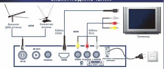
The simplest antenna option
Figure 1 shows the simplest zero-cost antenna design. It is made from a piece of mounting wire 60 cm long.
Connector X1 in the figure is shown conditionally, because I simply plugged the cut and twisted end of the wire into the antenna socket of the set-top box (in the central hole). At the second end there is a ring that can be hung on a nail on the wall or on the handle of a window frame, for example.
Rice. 1. The simplest version of the T2 antenna with zero cost.
All channels started working. The image quality is excellent, although the signal level shows only 15-20%. I would like to note that in the same apartment, reception on the collective antenna, which normally received analogue channels, turned out to be impossible.
But this piece of wire is fine. Although the signal level, judging by the readings of the set-top box, is very small.
Video
Coffee capsule Nescafe Dolce Gusto Cafe O Le Coffee with milk, 3 packs of 16 capsules each
1305 ₽ More details
Coffee capsules Nescafe Dolce Gusto Café Au Lait, 16 pcs.
435 ₽ More details
Shockproof smartphones
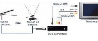
Antenna connection
Even a properly designed and well-made antenna will perform poorly if there are errors in the connection.
The following conditions must be met:
- Use shielded cable.
- Securely solder contacts and connectors.
- Make sure that the core and screen are tightly connected to the radio input group.
- Ground the antenna.
- If there is interference when powering the radio from the network, when there is no ground wire in the socket, it is better to connect the radio or transistor to ground. For this purpose, most devices have a special socket or terminal.
If the reception quality is not satisfactory, and changing the location and direction of the antenna does not help, you will have to install an amplifier.
A simple and low-cost circuit of such a device is assembled, for example, on an RFMD SPF5043Z microcircuit. The advantage of the design is that the board can be made without chemicals on a 2-sided PCB measuring 15-20 mm and placed in a shielded case.
Simple 160 meter antennas
A simple and effective antenna for the 160 m range is the dream of almost every radio amateur, especially an inveterate “DX hunter”. How can you start working in this range without large technical and material costs? After all, the 160 m range places increased demands on both the radio amateur’s on-air skills and the design of antennas. If antennas for the 10, 15 or 20-meter range are still small in size, then making an antenna for the 160-meter range is not at all easy. There are a hundred or two happy radio amateurs who have managed to install full-size verticals in this range. You can, of course, use a 10-15 meter metal mast as a 160-meter antenna with antennas for short-wave HF bands, which will act as a capacitive load. And again the question arises: “How many radio amateurs are able to afford such luxury?”
As a result, after much thought and accompanying doubts, the “average” radio amateur still comes to the need to use a wire antenna - the most adequate design that can be implemented in practice. Typically, this is a full-size λ/4 or λ/2 driver powered by 50 ohm coaxial cable. If such an antenna is correctly installed and tuned to resonance, then in the selected frequency band there is no need for an antenna tuner or other matching device.
If you fix a horizontal 160-meter dipole at a height of 15 m above the ground, then it will be at a height of less than 0.1λ. It would seem to be quite a sufficient height. However, drawing an analogy with a 20 m range dipole, which, with a suspension height of 0.1λ, is located only 2 m from the ground (such a comparison is acceptable, since both antennas behave almost identically), it can be argued that such an installation is completely ineffective. Both antennas will emit radio waves at large angles to the horizon, almost to the zenith, which makes them practically unsuitable for long-range HF radio communications. A low-mounted dipole is only good for short-range radio communications. The 160-meter dipole, which emits at small angles to the horizon, must be located more than 40 m (0.25λ) above the ground.
However, the capabilities of the “average radio amateur” most often do not allow the use of a height of more than 20-30 m. The optimal radiation angle of a 160-meter antenna is in the range from 30 to 35 °, although at higher frequency ranges it is significantly lower - 5-10 °. The main determining factor for choosing the optimal radiation angle on certain paths is the state of the ionosphere. It sets, depending on the direction towards the correspondent, the solar cycle, the time of year and the corresponding time of day, the corresponding optimal angle of incidence (entry) for the radio wave. Due to these factors, the angle of incidence of the radio wave is subject to constant changes, and this explains the fact that DX signals are briefly received louder by a low-hanging antenna compared to an antenna with a low radiation angle. This phenomenon, however, always manifests itself only momentarily and does not say anything about the actual relationships, i.e. that for DX radio communications, an antenna with a low radiation angle is, of course, preferable to a low-hanging dipole. One of the American radio amateurs once very correctly noted: “The optimal angle of signal emission is determined not by the radio antenna, but by the ionosphere, located significantly higher.”
When considering the design of any antenna, one of the important points is the distribution of current in it. The emission of electromagnetic energy by an antenna occurs where current flows. Moreover, the stronger the current, the greater the strength of the electromagnetic field, which means that the higher the current-carrying parts of the antenna are located, the better it will ultimately function.
If we consider the radiation characteristics of a horizontal dipole, we can see that the maximum radiation occurs in the area in which the antenna is powered. The outer (end) parts of the dipole almost do not emit electromagnetic energy and are required by the antenna, roughly speaking, to achieve resonance. This fact can be used when designing a 160-meter antenna without noticeable loss of its positive radiating properties.
A vertical quarter-wave emitter, in principle, is nothing more than a “half-dipole”, so the mentioned properties fully apply to this antenna, which is very popular among many radio amateurs. Here, the radiation maximum is also located near the feed point.
A resonant dipole that has a fairly low radiation angle is the Inverted V antenna.
Inverted Vee
The inverted V-shaped design requires only one support mast. Both wire emitters are located at an angle to the ground and should end approximately 3 m from it in order to prevent touching them, because When the transmitter is operating, high RF voltage is present at the ends of the emitters. The angle between the emitters is at least 60°, the total length of both emitters for the central frequency of 1.85 MHz is 76.7 m, for the central frequency of 1.9 MHz - 74.68 m.
As you know, a high-mounted horizontal dipole has an input impedance of 72 Ohms, but it decreases the more the closer the antenna is located to the surface of the earth. Therefore, according to experimental data, the total impedance of an Inverted V antenna is about 50 Ohms, and such an antenna can be powered with a 50 Ohm coaxial cable through a 1:1 balun.
Many publications on the Inverted V antenna claim that it works successfully without a balun and can be powered directly with a 50-ohm cable. However, in practice, this simplification often leads to the appearance of current on the outer side of the cable braid, and it becomes an unnecessary part of the antenna system. The Inverted V antenna is absolutely symmetrical, therefore, when feeding it with a coaxial cable, it is strongly recommended to use a balancing device.
It was already indicated earlier that the maximum radiation from the antenna occurs in those places where a large current flows. For some antennas (for example, for a quarter-wave vertical) this is the lower part, i.e. directly at the food point. At the top of the antenna the current is weaker and therefore this part of the antenna does not play a large role in the radiation. If you make the upper part of the antenna from wire and place it horizontally, then the radiating properties of the antenna will not deteriorate significantly.
Inverted L
Such an antenna was called Inverted L (in Russian-language literature another name is widely used - L-shaped antenna). The Inverted L antenna radiates predominantly at low angles to the horizon. The rule for this antenna is:
“The higher the vertical portion of the antenna, the better its DX properties.”
Therefore, you should always try to place the vertical part of the antenna as high as possible. The approximate total length of such an antenna is 39 m. If there are tall trees in the area, then they can be used when installing the Inverted L antenna. In addition, modern fiberglass poles are a very suitable support material for such an antenna.
For the Inverted L antenna, as for any other quarter-wave emitter, counterweights with a length of 38-41 m are required, depending on the antenna tuning frequency and the conditions for placing the counterweights. If they are buried in the ground, then the more counterweights, the better. But the number of counterweights isolated from the ground (and even more so, located above it) can be significantly less—two to four wires will be quite enough. A metal rod(s) buried in the ground to a depth of 2-3 m can somewhat improve the operation of the counterweight system.
The total impedance of this antenna system under ideal conditions is 38 ohms. In reality it is slightly higher, so it is possible to power the Inverted L antenna with 50 ohm coaxial cable. If you increase the length of the quarter-wave vertical or Inverted L antenna to 50 m, then its active resistance at the feed point will increase (to approximately 50 Ohms). True, this will lead to the fact that the antenna will no longer be resonant, and the reactive component of the total input impedance will be inductive. To compensate for this reactivity, it is enough to install a variable capacitor with a maximum capacitance of about 500-600 pF at the power point. Even a capacitor from old tube receivers, which may not have a high dielectric strength, is quite suitable here, because it serves to electrically shorten the antenna in order to obtain system resonance in the range of 160 m. By adjusting the capacitance of the variable capacitor, the antenna is tuned to resonance in the selected part of the range.
Another popular 160 m antenna is the sloper. The name “sloper” (from the English slope) characterizes both the form of installation of the antenna (at an angle to the ground) and the type of its radiation (at an angle to the horizon). On low-frequency HF bands, the sloper is an effective, relatively small-sized DX antenna that is successfully used by many radio amateurs. The current-carrying part of the system is located high and away from interfering objects on the ground, and the polarization of the radiation is predominantly vertical.
It is necessary to distinguish between quarter-wave
Four-wave sloper
and half-wave sloper.
Half-wave sloper
To install any of these antennas, one mast is enough. In this case, the lower end of the antenna, according to safety requirements, must end at a height of 2-3 meters above the ground. In the direction of the stretched wire, the sloper has a slight gain (according to some data it is 2-3 dB), while from the rear side there is a weakening of the signal. Therefore, it is recommended to install the sloper in the preferred direction.
The quarter-wave sloper has a length of about 40 m (38.51 m for a frequency of 1.85 MHz, 37.5 m for 1.9 MHz). The grounded mast acts as a counterweight. This antenna is powered by a 50 ohm coaxial cable. The inner conductor of the cable is connected to the wire emitter, and the cable braid is connected to the mast.
Based on experience, setting up a quarter-wave sloper is not that easy. Often, tuning a system to the required frequency and achieving an input impedance of about 50 ohms requires a significant investment of time and effort. The fact is that the resonance of the antenna depends on the size of the mast, soil conductivity, length of the emitter, its angle of inclination to the ground, etc. Based on this, the angle of inclination of the emitter and its height above the ground are decisive factors in determining the total input impedance of the antenna.
However, many quarter-wave slopers start working right out of the box, so don't be afraid to take on this antenna. Keep in mind that it is built to last, and once it's set up, you can enjoy its performance.
The half-wave sloper is actually a classic half-wave dipole mounted at an angle to the ground. Such an antenna compares favorably with a quarter-wave sloper by its consistently predictable parameters, so painstaking tuning, as is the case with a quarter-wave sloper, is not required.
The total length of the half-wave sloper is about 77 m for a frequency of 1.85 MHz (75 m for a frequency of 1.9 MHz). In a half-wave sloper, they deliberately refuse to use a balun, because it would most likely neutralize the positive properties of this antenna. The fact is that with an asymmetrical supply, the directional pattern of the dipole is slightly “skewed”; the radiation characteristic is distorted in the direction of the “hot” shoulder, which is connected to the internal conductor of the coaxial cable. This effect can be used to additionally “press” the radiation toward the ground. Another advantage of the half-wave sloper is that it can be optimally “tailored” to existing local conditions. To do this, the “cold” end of the antenna is passed through a guide roller and pulled vertically down (usually at a distance of 1-2 m from the building or mast).
The roller is fixed at the highest point. Thus, you can change the length of the antenna and optimally “fit” it into local conditions. When installing the described antennas, it should be borne in mind that very rarely the antenna resonates at the design frequency, therefore, as a rule, the antenna needs fine tuning. In this regard, it is useful to know that the length of the quarter-wave driver should be changed to 208 cm in order to achieve a resonance shift of 100 kHz. In a half-wave dipole, this will require changing the length by 416 cm, and in the Delta Loop antenna by 832 cm.
RELATED ARTICLES ON THE TOPIC:
- Available antennas for the 160 m range A simple and effective antenna for the 160 m range is the dream of almost every radio amateur, especially an inveterate “DX hunter”. How can you start working in this range without large technical and material costs? After all, the 160 m range places increased demands on both the skills of a radio amateur on the air,...
- Wideband sloper 80 m range This antenna operates in the range of 3500...4000 kHz while maintaining good SWR. The Inverted V antennas and half-wave inclined dipoles I had previously used did not give the desired results over a wide frequency range. The antenna is an inclined radiator with two (or more) counterweights located in a plane at an angle...
- Design of a dual-band antenna (3.5 and 7 MHz) with a switchable radiation pattern The design of a dual-band antenna (3.5 and 7 MHz) with a switchable radiation pattern was proposed by Gerd Bellenhaus, DJ6IG and Carl Hills, DL1VU. The antenna is based on four identical slopers suspended on a mast 18 m high for rotating antennas for the HF ranges, fed from the upper end by 50-ohm cables, the braid of which...
- Dual-band sloper The SLOPER antenna shown in the figure can be installed in a minimal area and can be successfully used in the 40 and 160 m bands. The antenna is manufactured by ALPHA DELTA in the USA….
- All-wave antenna of the “poor” radio amateur When designing and operating your “antenna field”, you have to constantly maneuver on a tiny patch of roof between elevator boxes, ventilation shafts, all kinds of television, satellite and other antennas, various cable communications, open radio broadcasting wiring... In addition, you should take into account the very detrimental all-season “harvest season”