Correct connection of the welding inverter prevents emergency situations and ensures the convenience of performing work operations. The instructions in the accompanying documentation provide a general procedure. To avoid problems, you should carefully study the rules for handling equipment, consider the use of extension cords and autonomous power supplies.
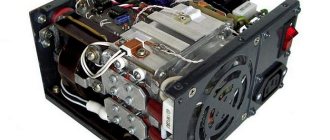
Inverter welding machine.
Welding inverter and its operating principle
To connect metal parts, high heating of the working area is used. The molten parts, after lowering the temperature, form a strong seam with a uniform internal structure. This mount is different:
- durability;
- strength;
- resistance to mechanical and other external influences.
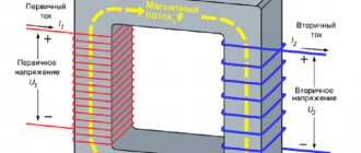
The melt zone (welding pool) is created using an electric arc. An inverter is a device that generates the output signal necessary to ignite it. Equipment in this category is connected to a 220 V or 380 V network. After rectification, the current is converted to alternating current.
Increasing the frequency allows you to reduce the size and weight of the transformer. The final stage is the reverse conversion to high direct current (20-260 A) with a corresponding reduction in voltage.
A typical household inverter device is designed to connect to a standard 220V network. The equipment is equipped with:
- digital indicator of operating parameters;
- current regulator;
- LED overheat alarm.
Principle of operation.
The automation unit provides:
- “hot” (quick) start;
- correction of the output signal to prevent sticking of the electrodes.
Connecting cables are supplied as standard. Protective devices and technological accessories along with consumables are purchased separately.
Equipment check
Before connecting the power source, the integrity of the housing and regulator handles is checked by external inspection. Organize the workplace as follows:
- clear a flat area (metal table);
- set a minimum distance of 2 m from the device to the walls;
- connect the protective grounding circuit;
- eliminate explosive (flammable) objects.
Effective ventilation of the room during welding is recommended to prevent harm to health from the polluted atmosphere. You need to prepare a mask, leggings, and electrodes in advance. Free passage of unauthorized people into the work area should be prevented. Remove foreign objects that interfere with individual operations.
We recommend reading Welding inverter Resanta SAI-250
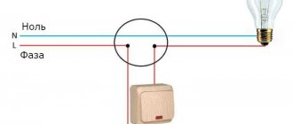
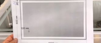
Electrical connection diagram
Welding of thick (16-17 mm) sheets of metal is performed with 6 mm electrodes at a set output current of 240±20A. In this mode, the load on the power supply increases, which is accompanied by a voltage drop. If the corresponding value is less than the permissible operating parameters, the automation will turn off the inverter.
Another problem is limited wiring options. Aluminum (copper) conductors of the household network are designed for 10 (16) A. It is recommended to check the compliance of the power consumption of the device with the operating parameters of the circuit breakers and fuses.
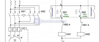
The figure shows a connection diagram for a welding machine, which minimizes the influence of powerful equipment on other equipment:
Welding machine connection diagram.
It is recommended to straighten the network cable. A bent conductor creates inductive reactance, which increases the load on the power supply. The areas that form the coils overheat until the protective shell is destroyed.
Subtleties of connection
For inverter semi-automatic devices, “phase” or two “phase” wires are used in combination with “zero”, as well as green or yellow conductors for grounding. Power is supplied via a plug that meets thermal throughput standards. The return cable is connected to the ground terminal. To improve contact and avoid voltage losses, special tips are soldered to the latter.
In devices operated from a three-phase network, the first wire goes to the “phase” of the power supply, the second to the neutral output, and the third to the protective “zero”. Before connecting a household welding machine to a three-phase 380 V network, determine where the thin input ends are and where the thick output ends are. Then connect two of them to any two “phases”, the third to the protective “neutral” wire.
Other DIY connection methods
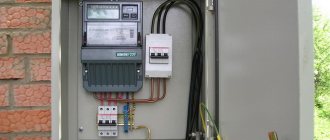
In an older home, the protective devices, wiring, and outlets are not designed to withstand heavy loads. High current causes a short circuit. Voltage surges can damage household appliances in your own apartment and those of your neighbors. To eliminate connection problems, you should consider solving this and other typical problems.
Using a current generator
To organize autonomous power supply, a compact power plant with a gasoline (diesel) engine is used. Such a generator can be purchased or rented for the duration of work operations. When choosing equipment, check:
- power;
- voltage stabilization;
- compliance with working conditions.
Calculation of output parameters for the considered example with welding of thick sheets:
- current – 240 A;
- voltage – 40 V;
- power – 9600 W = 240*40.
A 10 kW generator in this mode will operate at the limit of its capabilities. This reduces the life of functional units and increases the risk of overheating and breakdowns. To eliminate negative factors, choose a source with a power reserve of 25±5%.
Using extension cords
The length of the serial network cable does not exceed 4 m. To expand the working area, a “carrying” is used. If the welding current is not more than 150 A, a 20-meter extension cord with a conductor cross-sectional area of 2.5 mm square is suitable. The power line is installed without bends to eliminate the parasitic influence of inductive reactance.
We recommend reading How an inverter welding machine works
Selecting cable parameters
To transmit high current, a conductor with a large cross-section in a thick protective sheath is used. Fixed terminals are used to connect to the welding machine. When choosing a cable, pay attention to the following details:
- copper conductor provides low resistivity;
- the use of aluminum reduces the cost of the product;
- the multi-core design maintains the integrity of the core after repeated twisting/straightening cycles;
- The shell with special additives is resistant to high and low temperatures.
Important parameters of cable products are determined by special markings in the name:
- HL (T) – the product is intended for use in cold climates down to -60°C (tropical);
- N – non-combustible insulation;
- KG – flexible cable;
- PES is a modification for a semi-automatic device.
A suitable cross section is selected taking into account the current strength (maximum):
- 6 mm sq. – 100 A;
- 10 – 120;
- 25 – 200;
- 35 – 290;
- 50 – 300.
| Conductor cross-sectional area, mm sq. | |||
| Current (I), A | Cable length, m | ||
| 0-15 | 15-30 | 30-60 | |
| 30-100 | 25 | 25 | 50 |
| 100-200 | 35 | 50 | 70 |
| 200-300 | 50 | 70 | 90 |
For an accurate calculation, use the formula D=S/K, where:
- D – permissible length;
- C – cross-sectional area;
- K – correction factor (K=I/100).
When checking the package, in addition to the cable, you should select the correct holder and clamp for connecting the ground.
When choosing a cable, you need to pay attention to a number of details.
How to find out the cross section
The main technical characteristics of conductors: cross-section, diameter and other important properties are indicated in catalogs or corresponding descriptions. However, if the contractor does not have the opportunity to familiarize himself with this data, and the question of how to determine the cross-section of the welding cable needs to be answered, then you should remember some recommendations.
There are several ways to determine the cross-section of a conductor. They all boil down to the fact that first you need to calculate the diameter of the core. This can be done using a micrometer or caliper. However, the simplest method, which does not require special accessories, is to use the following method.
The contractor will need to remove the insulation from the conductive core. Then you need to wind the core around a cylindrical object (screwdriver) and use a ruler to measure the total length of the turns, the number of which for accurate calculations should exceed 10. In conclusion: the total length in mm. must be divided by the number of turns. The resulting value will be the diameter of the wire, from which the cross-sectional value can be found.
The contractor can find complete information about the cross-sections of cables of various brands in articles devoted to this topic:
Basics of using a welding inverter
At the preparation stage, the features of the technological process are clarified. A 2.5 mm electrode is used at a current of 90±10A for welding workpieces of the following thickness (mm):
- cast iron – 3 or more;
- stainless steel – 1.5;
- “soft” steel grades - from 2 to 5.
To find out how to connect a welding inverter under other initial conditions, use the reference data. Based on the results of the test seam, the operating parameters are adjusted.
As the current increases:
- the seam is deeper;
- you can move the electrode faster without compromising the reliability of the connection.
We recommend reading Schematic diagram of the inverter
Before welding, thoroughly clean the surfaces. Remove rust, grease, paint. To create a high-quality seam, both workpieces are heated with equal intensity.
Distribute the melt evenly on the sides. The reduction in electrode length and the corresponding change in arc parameters should be taken into account.
Training improves work skills. For beginners, markings highlight the connection line to improve visibility. The electrode is moved at an angle of 30-60°. Maintain a constant arc length of 2-3 mm.
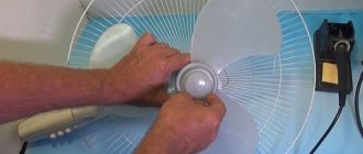
How to extend the cable on an inverter
Typically, the inverter is equipped with a wire no more than two meters long. Working with such a cable is quite problematic and inconvenient. Therefore, performers often have a question: how to extend the cable on a welding machine ?
Previously, we considered that connecting welding cables should be done in several ways, each of which is used depending on the skills of the performer, the presence or absence of specialized equipment and additional accessories.
It is important to know how to extend a welding cable. The connection of welding cables during extension can be performed using the following methods: welding; soldering; crimping.
It is also worth noting the opinion of some professionals who are against lengthening the conductors . Cables that are too long may adversely affect the performance of the device. In addition, the longer the wire, the greater the current loss, which can negatively affect the quality of welding.
Connection with different polarity
Electrons move in a conductor from minus to plus. Therefore, the seam parameters depend on how to connect the clamp and ground cables, taking into account polarity.
The direct method is to connect the minus to the electrode. In this case, the heating of the workpiece improves. The technology is used to join thick sheets.
Reverse polarity is used to perform accurate work operations. The comparatively lower temperature effect prevents through-burning of thin products.
Precautionary measures
To safely reproduce technological operations, the following rules apply:
- check the integrity of the device and insulation;
- measure voltage (in idle mode U=0);
- check the compliance of the power supply network with the connected load;
- remove foreign objects from the work area;
- install protective grounding;
- create good ventilation and illumination;
- use shoes with rubber soles (mat, wooden flooring) to prevent electric shock;
- Use protective clothing, gaiters, and a mask.
Before creating a connection, check the voltage sag in the network by test welding at maximum current. It is recommended to place sand or other means to quickly extinguish a fire at a short distance from the work area.
Returning the stabilizer to the service center
Next, I must note the integrity of the seller of Resanta, I will call him Alexey here.
Alexey felt the complexity of my situation, showed a deep understanding of the situation and suggested that I deliver the stabilizer to the service center, although he himself, in Moscow. Fortunately, I’m from Podolsk myself, so it’s not far.
I won’t describe my road adventures before the service.
I had to go twice. For the first time, I took a three-phase monoblock to service and received a ticket to request an inspection of the device.
Three days later, Alexey got in touch.
During this time, I was thinking about getting a refund for a faulty device that had not passed field tests and did not live up to expectations. I also thought about replacing it with three single-phase ten kilowatt stubs.
I studied reviews about Resant. There was a lot of negativity, but there was also positivity.
Resanta has made a quantum leap in equipment assembly. Previously, there was some ugly soldering inside. The wires simply fell off.
Now everything is assembled without soldering on the connectors. And the places where the soldering has been preserved are soldered to a very high quality.
The electronic line of stabilizers is implemented on a relay. The relays click noisily and provide low accuracy and stabilization speed.
The electromechanical modification stabilizes quite accurately and smoothly. It buzzes a little, as mentioned earlier. But what will Russian people not get used to for the sake of significant savings?
I settled on replacing the three-phase device with three, ten kilowatt, electromechanical ones.
The exchange was made politely, at the service center on Nagatinskaya.
And here I am the happy owner of three block devices, assembled in the Baltics, securely installed in the trunk of my car, heading south from Moscow, observing the speed limit, of course.