Measuring voltage and current with a multimeter - what not to do.
A portable digital combined measuring instrument, or multimeter for short, is available in almost every home today.
Fortunately, the price of the simplest models (RUR 350-RUR 1000), which is enough for household use, allows you to purchase it without seriously cutting the family budget.
At the same time, it is not at all necessary to be a radio amateur to learn how to use this box.
However, amateurs, unlike radio technicians, often make such stupid mistakes that can lead not only to the failure of the device, but also result in the fire of this little thing.
How to avoid this, let's figure it out in this article.
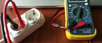
How to measure the current in an outlet and find out if it really corresponds to its declared characteristics (6A or 16A)? Like you stuck the probes in, and the device shows you Amperes.
The answer is no. The only thing that can be measured in an outlet with a multimeter is the alternating voltage.
Yes, sometimes a multimeter is used to check the continuity of the circuit in the socket or the presence of a short circuit in the electrical wiring, by testing and checking the resistance of the incoming cable.
But for this, not only the automatic sockets, but also the input switch must be turned off in the electrical panel.
In all other cases, “how much current is in the outlet” you will not know. Just check how well the protection works in your electrical panel.
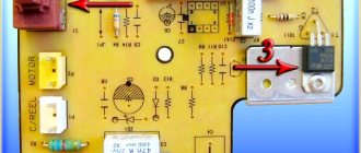
Here are the visual consequences of such measurements on the tips of the probes that were inserted into the socket to check the current strength. The current turned out to be stronger
And these are the consequences inside the multimeter itself.
Pay special attention - most cheap Chinese multimeters do not measure alternating current at all! This is indicated by the inscriptions on the case.
Near the connectors for the probes, where 200mA and 10A are written, a straight (-) or broken dotted (...) line icon is drawn. It means that this multimeter can only measure DC OR PULSATING CURRENT (from a battery, accumulator, power supply, etc.)
Sockets and household appliances are out of the question here! "Change" is indicated by a wavy line (
All modern multimeters have a battery inside the case, no matter which one - a 9V crown, AA batteries or round “tablets”.
It is important for you to know that if this same battery is severely discharged, the device will begin to lie shamelessly and its error will be tens of percent down or up.
Therefore, if the readings on the display give you doubts, there is no need to blame the tester and scold cheap Chinese products, just try replacing the battery.
There are devices that directly display the charge level of the built-in battery.
The capacity of finger or little finger batteries can be checked without a multimeter using a jumping test.
Round tablets are checked by LEDs.
But for the crown you will need a different multimeter.
Before taking any measurements with a multimeter, check whether you have disconnected the equipment being measured from the 220V network (with the exception of checking circuits in voltmeter mode).
The same applies to devices powered from a 12/24V constant voltage source. It would seem like a completely logical rule and everyone follows it
However, there is a catch. Please note that in this case you always need to pull the plug out of the socket, and not just click the built-in switch on the carrying case or the device itself.
The fact is that such a switch often breaks not two wires (phase and zero), but only one. This applies to extension cords with two-pole (they are narrower) rather than four-pole switches.
And here everything will depend on how you inserted the plug from the carrier or surge protector into the outlet. In one position the phase will be broken, and in the other - zero!
As you understand, in the second case, the phase will still be present on the device, regardless of whether you flicked the switch on the extension cord or not.
What happens if you mix it up and measure the voltage in current mode with a multimeter? As mentioned above, nothing good.
We explain the physics of the process. The fact is that when you insert the probes into the socket, you are actually connecting phase to zero through a multimeter.
In order not to provoke a short circuit, the tester must have a large internal resistance. This is precisely achieved by switching the device to the “voltage measurement” position and installing the probes in the correct sockets.
In practice, the R-multimeter in this position can be tens of megaohms. When measuring current, everything is quite the opposite. In this case, the multimeter is connected in series with the load.
The current that begins to flow through the tester should not be distorted and remain the same as it would be without the multimeter. Therefore, in current measurement mode, the internal resistance of the multimeter is very small.
If you try to measure the voltage in this position, it is the same as short-circuiting a phase wire with a neutral wire.
When the probes are in the COM and mA connectors, the built-in fuse will trip.
But if the second probe is in the 10A connector, everything will end much worse. In the cheapest Chinese models, such as the DT830B, the multimeter has no protection at all in this position. There is a shunt between the COM and 10A sockets!
Also be careful when measuring alternating voltage (ACV) and direct voltage (DCV). Many people seem to set the switch to volts, but do not notice that it is constant voltage (DCV).
Then they put the probes into the socket.
Therefore, before any measurements, double-check the position of the mode wheel and where the probes themselves are inserted.
Even experienced craftsmen advise additionally marking this risk immediately after purchasing the device.
It is because of this that some manufacturers began to make switches with a mirror scale in order to 100% eliminate this error.
Devices with auto-selection and a minimal set of buttons don’t always help either.
In more expensive models of multimeters, the probe sockets are automatically closed with protective shutters if the switch is selected incorrectly. For example, HoldPeak HP890CN.
If the probes are already placed where they are not needed, then you simply will not be able to turn the wheel into the wrong modes (foolproof). More details
Is it possible to measure motor current with a multimeter? It is possible, but you need to know certain nuances.
First, the multimeter must support AC current measurement mode. Check this by looking at the inscriptions on the device body.
There should be a wavy line near the Ampere icon, and the inscription AC should be displayed on the display.
Secondly, any asynchronous motor at the moment of starting consumes a current 5-7 times more than its rated values. Therefore, you should never be guided only by the data on the engine tag.
The measured current at the moment of starting will be much greater than the maximum limit of the multimeter (usually max 10A). It’s good if the device shows the value OL (Over Limit) or 1. (one with a dot).
This means exceeding the limit. In the worst situations, the device may fail.
You can use a single-pole circuit breaker built in series with one of the phases in the power circuit. The multimeter is connected in parallel to it.
At the moment of starting, all the current will initially flow through the machine. When the engine accelerates and reaches the specified mode, the machine turns off (de-shunting is performed).
The rated current changes its path and begins to flow through the multimeter, on which the true readings are recorded.
You can also use additional devices. They are called clamp adapters.
Connect such an external connector through the probes and turn your multimeter into a full-fledged current clamp with the ability to measure current up to 600A!
More details
Both variable and constant.
All multimeters for measuring current have two probe positions:
General purpose
This is a multifunctional device designed to measure a number of electrical current parameters. A modern multimeter, even a semi-professional one intended for household needs, is capable of measuring:
- alternating and direct voltage;
- alternating and direct current (current strength);
- resistance.
This is a minimum list of functions that even the simplest device has. More complex ones have functions for testing diodes and transistors, checking cable integrity, etc. There are models that even allow you to measure temperature.
An ordinary household appliance is used in networks whose voltage is not higher than 1000 volts DC or 750 volts AC. To measure high voltage, only a professional high-voltage multimeter is used.
Multimeter DT-830C does not display voltage correctly
- Author
- Message
Multimeter DT-830C does not display voltage correctly
Re: Simple human weaknesses
Re: Simple human weaknesses
Re: DT-830C multimeter displays incorrect voltage
It is useful to start any repair by measuring the voltages in the sensitive components of the circuit. According to the specification for the ICL7106 "drop" on which all these multimeters are built, here it is the reference voltage VREF HI, which should be 100 mV at the REF HI pin.
The specification for the ICL7106 suggests that the measured voltage is displayed using the formula:
DISPLAY COUNT = 1000 (VIN/VREF), where VIN is the voltage after the input divider and VREF is the 100 mV reference voltage at the REF HI pin.
Re: DT-830C multimeter displays incorrect voltage
Yes, that's right. Reference voltage 100 mV.
I set the reference to 100 mV + -0.8%, naturally, the device lies a little, but it’s tolerable. In place of R there should be 2 MΩ, but there was 1 MΩ. I installed an assembly of 3 resistors (1.98 MOhm). I replaced R21(900) with 100 Ohm, soldered a 1 MOhm resistor in parallel with R22.
These might be useful: diagrams, boards.
PS here they say that the “drop” is over.
Re: DT-830C multimeter displays incorrect voltage
Re: DT-830C multimeter displays incorrect voltage
Re: DT-830C multimeter displays incorrect voltage
Deep repairs of such multimeters are not cost-effective. But sometimes, there is no way to live, but we need to restore it, regardless of the cost. There was a big discussion about replacing the ICL7106 microcontroller on the https://pro-radio.ru/ forum, but after some disturbances it got lost. Thank you, user AK collected everything on the topic: Selection on Dropbox Replacing the ICL7106 blot in a multimeter.pdf Replacing the ICL7106 blot in a MASTECH MY64 multimeter.
Re: DT-830C multimeter displays incorrect voltage
Re: DT-830C multimeter displays incorrect voltage
Will they come in handy? Not sure. When I burned the first “cartoon” by mistake, I was very worried. And now there are already several of them in the desk drawer. It would be a shame to throw everything away.
Your DT-830C has a beeper, but a timer based on HCF4013 (K561TM2) is useful for saving batteries. Especially if the damaged “drop” consumes more than normal. The article contains a diagram and drawing of the add-on printed circuit board, as well as a diagram of the M-830B device. Source: Repair of electronic equipment, 2002, No. 04, p. 36.
DOMOSTROYPlumbing and construction
- home
- Connect with us
- Thursday, December 12, 2022 1:08
- Author: Sereg985
- Comment
- Category: Construction
- Link to post
- https://firmmy.ru/
Organizing and repairing a multimeter independently is within the capabilities of every user who is well acquainted with the basics of electronics and electrical engineering. But before you begin such repairs, you need to try to understand the nature of the damage that has occurred.
Visually detectable defects (manufacturing defects)
It is most convenient to check the serviceability of the device at the initial stage of repair by examining its electronic circuit. For this case, the following troubleshooting rules have been developed:
- it is necessary to carefully examine the printed circuit board of the multimeter, which may have clearly visible factory defects and errors;
- Particular attention should be paid to the presence of unwanted short circuits and poor-quality soldering, as well as defects on the pins along the edges of the board (in the area where the display is connected). For repairs you will have to use soldering;
- Factory errors most often manifest themselves in the fact that the multimeter does not show what it should according to the instructions, and therefore its display is examined first.
If the multimeter gives incorrect readings in all modes and the IC1 chip heats up, then you need to inspect the connectors to check the transistors. If the long leads are shorted, then the repair will simply consist of opening them.
In total, there can be a sufficient number of visually detectable faults. You can familiarize yourself with some of them in the table and then eliminate them yourself. (at: https://myfta.ru/articles/remont-multimetrov.) Before repairs, you need to study the multimeter diagrams, which are usually given in the passport.
What else to pay attention to
NCV function. When this option is activated, the device signals with sound/light that a “dangerous” voltage is nearby. This multimeter can be used as a hidden wiring detector. Literally, this function is called non-contact voltage detection.
True RMS function. Designed for more accurate measurements of alternating current with an imperfect sine wave.
Memory and freezing of readings. If you press the HOLD button, the readings on the display will be frozen, which is convenient in difficult-to-read measurement conditions. The ability to record data in memory with the ability to view and upload is an option on expensive devices.
Uploading data. Advanced multimeters are capable of transmitting data to a PC via cable. There are devices with a Bluetooth module that transfer data to a smartphone and then to the cloud.
Nutritional features. Multimeters with a 9-volt Krona element and several AAA batteries are available to choose from. Industrial grade multimeters are equipped with a Li-ion battery. It is worth giving preference to a device with a low battery charge alarm or with a charge level indication.
Checking the display
If they want to check the serviceability and repair the multimeter indicator, they usually resort to the help of an additional device that produces a signal of a suitable frequency and amplitude (50-60 Hz and units of volts). If it is not available, you can use a multimeter type M832 with the function of generating rectangular pulses (meander).
To diagnose and repair the multimeter display, you need to remove the working board from the device body and select a position convenient for checking the indicator contacts (screen up).
After this, you should connect the end of one probe to the common terminal of the indicator under study (it is located in the bottom row, far left), and with the other end, alternately touch the signal terminals of the display.
In this case, all its segments should light up one after another according to the wiring of the signal buses, which should be read separately. Normal “activation” of the tested segments in all modes indicates that the display is working properly.
Additional Information. This malfunction most often manifests itself during the operation of a digital multimeter, in which its measuring part fails and requires repair extremely rarely (provided that the requirements of the instructions are met).
The last remark concerns only constant quantities, when measuring which the multimeter is well protected against overloads. Serious difficulties in identifying the causes of device failure most often occur when determining the resistance of a circuit section and in testing mode.
Testing the wire with a multimeter
1. Install the probes into the multimeter connectors:
— Red probe into the V Ω mA
— Black probe into COM
2. We switch the control wheel to the dialing mode, which is marked accordingly (diode and buzzer icon). One should appear on the screen.
3. We check the correct operation of the multimeter by connecting the contacts of the probes by shorting them.
If the device is working correctly, you will hear a buzzer sound and a value close to zero will appear on the screen.
4. We call the wire. By applying the multimeter probes to its wires on both sides, as shown in the image below. If the conductor is intact, then you will immediately hear a buzzer sound, and the readings on the screen will be close to “0”, for example 0.001.
If the wire core is damaged and one of its ends does not have an electrical connection with the other, then the multimeter readings will not change, “1” will be displayed and there will be no sound signal.
As you can see, everything is quite simple, and if you have a multimeter at hand, you can try to ring something yourself. I’ll just remind you once again - don’t call back under tension, even if it’s low voltage.
Problems related to resistance testing
In this mode, characteristic faults, as a rule, appear in measuring ranges up to 200 and up to 2000 Ohms. When extraneous voltage comes into contact with the input, as a rule, resistors designated R5, R6, R10, R18, as well as transistor Q1, burn out. In addition, capacitor C6 often breaks through. The consequences of exposure to extraneous potential are manifested as follows:
- when triode Q1 is completely “burnt out”, when determining the resistance, the multimeter shows only zeros;
- in case of incomplete breakdown of the transistor, the device with open ends should show the resistance of its transition.
Note! In other measurement modes, this transistor is short-circuited and therefore does not affect the display readings.
In the event of a breakdown of C6, the multimeter will not work at the measuring limits of 20, 200 and 1000 Volts (the possibility of a strong underestimation of readings is not excluded).
If the multimeter constantly beeps when dialing or is silent, then the cause may be poor-quality soldering of the pins of the IC2 microcircuit. Repair involves careful soldering.
How to use a multimeter. Part 2
Good afternoon friends!
In the first part of the article, we learned how to measure voltage. Now you can show off your erudition among friends and acquaintances)) Today we will increase our intellectual knowledge and learn how to measure the second important quantity - electric current.
Current measurement
To begin with, let us remember that electric current is the directional movement of electric charges. And the old school joke - “electric current is like a lazy person - it goes where it’s easier for it.” “Easy” means that the electrical circuit has little resistance. The lower the resistance of the circuit at the same voltage, the greater the current in it. You and I remembered Ohm's law.
Now let's look at our UT2001 multimeter.
The following switch positions, below the voltage measurement area, are responsible for measuring direct and alternating currents .
The letter A (Amper, ampere, a unit of measurement of current) is marked on the multimeter body in this area.
Current strength can be measured in the ranges 0 - 2 mA (milliamps), 0 - 20 mA, 0 - 200 mA, 0 - 10 A.
Please note that when measuring current, one probe (black) must be connected to the common wire of the device (black socket), and the second (red) to one of the two inputs, under which it is written “A” or “10A”.
Problems with the ADC
It is recommended to begin the inspection and repair of a non-working multimeter, the malfunction of which is not related to the cases already considered, by checking the 3 Volt voltage on the ADC supply bus. In this case, first of all, you need to make sure that there is no breakdown between the supply terminal and the common terminal of the converter.
The disappearance of indication elements on the display screen in the presence of a supply voltage to the converter most likely indicates damage to its circuit. The same conclusion can be drawn if a significant number of circuit elements located near the ADC burn out.
In practice, this unit “burns out” only when a sufficiently high voltage (more than 220 Volts) is applied to its input, which manifests itself visually in the form of cracks in the module’s compound.
ADC testing
Before we talk about repairs, it is necessary to carry out an inspection. A simple way to test an ADC for suitability for further operation is to test its outputs using a known-good multimeter of the same class. Note that the case when the second multimeter incorrectly displays measurement results is not suitable for such a test.
When preparing for operation, the device is switched to the diode “testing” mode, and the measuring end of the wire in red insulation is connected to the “minus power” terminal of the microcircuit. Following this, each of its signal legs is successively touched with a black probe.
Since the circuit inputs have protective diodes connected in the reverse direction, they should open after applying forward voltage from a third-party multimeter.
The fact of their opening is recorded on the display in the form of a voltage drop across the junction of the semiconductor element. The circuit is checked in the same way by connecting a probe in black insulation to pin 1 (+ ADC power supply) and then touching all other pins. In this case, the readings on the display screen should be the same as in the first case.
When changing the polarity of the connection of the second measuring device, its indicator always shows a break, since the input resistance of the working microcircuit is quite high.
In this case, the terminals that in both cases show the final resistance value will be considered faulty. If, with any of the described connection options, the multimeter shows a break, this most likely indicates an internal break in the circuit.
Scheme and operation of the device
Rice. 1. Block diagram of ADC 7106
The basis of the multimeter is the ADC IC1 type 7106 (the closest domestic analogue is the 572PV5 microcircuit). Its block diagram is shown in Fig. 1, and the pinout for execution in the DIP-40 housing is shown in Fig. 2. The 7106 core may have different prefixes depending on the manufacturer: ICL7106, TC7106, etc. Recently, DIE chips have been increasingly used, the crystal of which is soldered directly onto the printed circuit board.
Rice. 2. Pinout of ADC 7106 in DIP-40 package
Let's consider the circuit of the M832 multimeter from Mastech (Fig. 3). Pin 1 of IC1 is supplied with a positive 9 V battery supply voltage, and pin 26 is supplied with a negative voltage. Inside the ADC there is a source of stabilized voltage of 3 V, its input is connected to pin 1 of IC1, and the output is connected to pin 32. Pin 32 is connected to the common pin of the multimeter and is galvanically connected to the COM input of the device. The voltage difference between pins 1 and 32 is approximately 3 V in a wide range of supply voltages - from nominal to 6.5 V. This stabilized voltage is supplied to the adjustable divider R11, VR1, R13, and its output is fed to the input of microcircuit 36 (in measurement mode currents and voltages). The divider sets the potential U eg at pin 36, equal to 100 mV. Resistors R12, R25 and R26 perform protective functions. Transistor Q102 and resistors R109, R110nR111 are responsible for indicating low battery power. Capacitors C7, C8 and resistors R19, R20 are responsible for displaying the decimal points of the display.
Rice. 3. Schematic diagram of the M832 multimeter
The range of operating input voltages Umax directly depends on the level of the adjustable reference voltage at pins 36 and 35 and is:
The stability and accuracy of the display readings depends on the stability of this reference voltage. The display readings N depend on the UBX input voltage and are expressed as a number:
Let's consider the operation of the device in the main modes.
Voltage measurement
A simplified diagram of a multimeter in voltage measurement mode is shown in Fig. 4. When measuring DC voltage, the input signal is applied to R1. R6, the output of which is fed through a switch (according to scheme 1-8/1. 1-8/2) to the protective resistor R17. This resistor, in addition, when measuring alternating voltage, together with the capacitor SZ, forms a low-pass filter. Next, the signal is supplied to the direct input of the ADC chip, pin 31. The common pin potential generated by a stabilized voltage source of 3 V, pin 32, is supplied to the inverse input of the chip.
Rice. 4. Simplified circuit of a multimeter in voltage measurement mode
When measuring alternating voltage, it is rectified by a half-wave rectifier using diode D1. Resistors R1 and R2 are selected in such a way that when measuring a sinusoidal voltage, the device shows the correct value. ADC protection is provided by divider R1. R6 and resistor R17.
Current measurement
Rice. 5. Simplified circuit of a multimeter in current measurement mode
A simplified circuit of a multimeter in current measurement mode is shown in Fig. 5. In the DC current measurement mode, the latter flows through resistors RO, R8, R7 and R6, switched depending on the measurement range. The voltage drop across these resistors is fed through R17 to the input of the ADC, and the result is displayed. ADC protection is provided by diodes D2, D3 (may not be installed in some models) and fuse F.
Resistance measurement
Rice. 6. Simplified circuit of a multimeter in resistance measurement mode
Problems with the rotary switch
Repair will be required if problems arise due to loss of contact in the circular biscuit switch. This manifests itself not only in the fact that the multimeter does not turn on, but also in the inability to obtain a normal connection without pressing hard on the biscuit. This is explained by the fact that in cheap Chinese multimeters, the contact tracks are rarely covered with high-quality lubricant, which leads to their rapid oxidation.
When used in dusty conditions, for example, after some time they become dirty and lose contact with the switch bar. To repair this multimeter assembly, it is enough to remove the printed circuit board from its body and wipe the contact tracks with a cotton swab dipped in alcohol. Then a thin layer of high-quality technical Vaseline should be applied to them.
In conclusion, we note that if contacts are detected or shorted in the multimeter, these shortcomings should be eliminated by using a low-voltage soldering iron with a well-sharpened tip. If you are not completely sure of the cause of the device failure, you should contact a specialist in the repair of measuring equipment.
Typical malfunctions of MASTECH multimeters
Before diagnosing, make sure the battery is working properly. Replace the battery if necessary. Never leave the probe in socket “10A” after finishing measurements! A short circuit will burn the circuit board tracks under the switch or the chip. This is not recoverable!
Error – Switching at the moment of measurement
It is strictly prohibited to switch the measurement range wheel directly during measurements.
It is because of such switching that the tracks in the switch area most often burn.
To move the device to another position, the probes (or at least one probe) must be disconnected from the object being measured.
Most often, this error is observed when there are “crocodiles” on the probes.
Repair of multimeter DT-838
Repair of multimeter S-Line DT-838
I checked the transistors with a tester and they turned out to be all faulty, I almost threw them out. But it turned out that the multimeter was faulty. (ha ha)
And so the multimeter was buggy when measuring resistance and when making a call, but it beeped. The voltage showed normal.
When I searched for a diagram I couldn’t find exactly this one, I came across this one:
Having disassembled the board, I noticed that R3 (the marking on the board is different on the diagram) there is a small point (152 is written on the resistor) 1.5 kOhm, measuring it with another multimeter (I have a generally glitchy one, but you can navigate it) showed more than 2 kOhm.
After the replacement everything worked. I took the resistor from the old computer motherboard, desoldered it and soldered it with a hairdryer on a homemade soldering station.
Share link:
Similar
on “Repair of multimeter DT-838”
please tell me the value of the resistor R16 is very necessary or the diagram if you have it, thanks in advance!
On my resistor R16 it says 561, which is 560 Ohms.
This photo is really hard to see
Same thing ((Where is this cut on the mother? I didn’t see it((tell me, or what to replace it with (where to remove it from)?
Found it... soldered it in... didn’t work ((or rather, it’s still buggy.
Repairing the dead is good. What about eliminating the factory (Chinese) defect? Now they sell DT-838 (allegedly) from different brands (Ermak, Resanta, TEK), but with the same defect, which appears ONLY when measuring temperature. Temperatures above 100-150 C are overestimated, and the higher they are, the more they are overestimated (see graph).
By heating the thermocouple from the multimeter kit in the flame of a lighter, it is easy to get 1999 C and even overload. In reality, it is quite difficult to get even 1000 C on a lighter, and at 1500 C the thermocouple conductors should have already melted.
The point, of course, is not in the thermocouple, but in the multimeters themselves: during the next Chinese “optimization” an error crept in, which has since been successfully replicated. Reviews mentioning a defect by Russian sellers are simply not published (I didn’t check all of them - one was enough)
I just found the error (in the board layout) (after a lot of sweat). It's easy to fix. The temperature becomes correct, and the correction does not affect other modes in any way. I'll probably post this somewhere more appropriate.
Repairing the dead is good. What about eliminating the factory (Chinese) defect? Now they sell DT-838 (allegedly) from different brands (Ermak, Resanta, TEK), but with the same defect, which appears ONLY when measuring temperature. Temperatures above 100-150 C are overestimated, and the higher they are, the more they are overestimated (see graph).
By heating the thermocouple from the multimeter kit in the flame of a lighter, it is easy to get 1999 C and even overload. In reality, it is quite difficult to get even 1000 C on a lighter, and at 1500 C the thermocouple conductors should have already melted.
The point, of course, is not in the thermocouple, but in the multimeters themselves: during the next Chinese “optimization” an error crept in, which has since been successfully replicated. Reviews mentioning a defect by Russian sellers are simply not published (I didn’t check all of them - one was enough)
I just found the error (in the board layout) (after a fair amount of sweat) and fixed it. It's easy to fix. The temperature becomes correct, and the correction does not affect other modes in any way. I'll probably post this somewhere more appropriate.
Why does my multimeter show the wrong voltage over the large resistor?
It's difficult for me to answer one specific question about our experiment. In our experiment, R1 and R2 were set to 1Meg each and then to 10k. I understand the need for R1 and R2 a bit. Without R1 and R2, the voltage distribution will not be exactly 50-50 for both D1 and D2 because the two diodes are not completely identical. D1 and D2 will have the same leakage currents (without R1 and R2) since they are just in series. However, they will likely have non-identical IV curves, so this particular leakage current will result in V@D1 /= V@D2.
The question I'm having trouble with is why V@R1 + V@R2 /= 10v when R1 = R2 = 1Meg? . On the other hand, these two voltages add up (to 10v) when R1 = R2 = 10k. I've included the 60 ohm source impedance in the diagram for completeness. However, as I see it, both D1 and D2 are reverse biased and hence they offer a very large (reverse resistance) which should be much greater than 60 ohms. Even with the parallel combination of 1Meg and D1 return resistance it should be much larger than 60 ohms. I tried to think of the answer in terms of RD1reverse //R1 = Req1 and RD2reverse //R2 = Req2. Req1 + Req2 (series) should still be much greater than 60 ohms, and I thought 10v would still show up at the D1 cathode node. However, in our experiment, V@R1 + V@R1 19 votes | asked by user139731 February 20, 2022 05:27:58 PM