What is the emf of the power source?
The electromotive force of the source is numerically equal to the potential difference at the ends of the element if it is open, which makes it possible to measure the EMF by voltage.
Interesting materials:
How to shoot video in the Bandicam game? How to reduce game power consumption? How to save the game in Metro 2033? How to save GTA 5 game saves? How to save in the game Detroit? How to save in the Far Edge game? How to save in the game Stalker Shadow of Chernobyl? How to save in Valheim? How to create a clan in Minecraft? How to create a new account in the game Durak online?
Electromotive force (EMF) of the energy source
To maintain an electric current in a conductor, an external energy source is required, which constantly creates a potential difference between the ends of this conductor. Such energy sources are called electrical energy sources (or current sources).
Sources of electrical energy have a certain electromotive force (abbreviated EMF ), which creates and maintains a potential difference between the ends of the conductor for a long time. It is sometimes said that emf creates an electric current in a circuit. We must remember that this definition is conventional, since we have already established above that the reason for the emergence and existence of electric current is the electric field.
A source of electrical energy produces a certain amount of work by moving electrical charges throughout a closed circuit.
Definition: The work done by a source of electrical energy when transferring a unit of positive charge throughout a closed circuit is called the emf of the source
The unit of measurement of electromotive force is the volt (abbreviated volt is denoted by the letter B or V - “ve” in Latin).
The emf of a source of electrical energy is equal to one volt if, when moving one coulomb of electricity throughout a closed circuit, the source of electrical energy does work equal to one joule:
In practice, both larger and smaller units are used to measure EMF, namely:
1 kilovolt (kV, kV), equal to 1000 V;
1 millivolt (mV, mV), equal to one thousandth of a volt (10-3 V),
1 microvolt (μV, μV), equal to one millionth of a volt (10-6 V).
Obviously, 1 kV = 1000 V; 1 V = 1000 mV = 1,000,000 μV; 1 mV = 1000 µV.
Currently, there are several types of electrical energy sources. For the first time, a galvanic battery was used as a source of electrical energy, consisting of several zinc and copper circles, between which skin soaked in acidified water was laid. In a galvanic battery, chemical energy was converted into electrical energy (this will be discussed in more detail in Chapter XVI). The galvanic battery got its name from the Italian physiologist Luigi Galvani (1737-1798), one of the founders of the doctrine of electricity.
Numerous experiments on the improvement and practical use of galvanic batteries were carried out by the Russian scientist Vasily Vladimirovich Petrov. At the beginning of the last century, he created the world's largest galvanic battery and used it for a number of brilliant experiments.
Sources of electrical energy that work on the principle of converting chemical energy into electrical energy are called chemical sources of electrical energy.
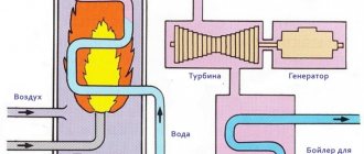
Another main source of electrical energy, widely used in electrical and radio engineering, is the generator. In generators, mechanical energy is converted into electrical energy.
On electrical diagrams, sources of electrical energy and generators are designated as shown in Fig. 1.
Figure 1. Symbols for sources of electrical energy: a - EMF source, general designation, b - current source, general designation; c - chemical source of electrical energy; g - battery of chemical sources; d - constant voltage source; e - source of variable intensity; g - generator.
In chemical sources of electrical energy and in generators, the electromotive force manifests itself in the same way, creating a potential difference at the source terminals and maintaining it for a long time. These terminals are called poles of the electrical energy source . One pole of an electrical energy source has a positive potential (lack of electrons), is indicated by a plus sign (+) and is called the positive pole. The other pole has a negative potential (excess electrons), is indicated by a minus sign (—) and is called the negative pole.
From sources of electrical energy, electrical energy is transmitted through wires to its consumers (electric lamps, electric motors, electric arcs, electric heating devices, etc.).
Definition: The combination of a source of electrical energy, its consumer and connecting wires is called an electrical circuit.
The simplest electrical circuit is shown in Fig. 2.
Figure 2. The simplest electrical circuit: B - source of electrical energy; SA - switch; EL—consumer of electrical energy (lamp).
In order for electric current to pass through a circuit, it must be closed. Current continuously flows through a closed electrical circuit, since there is a certain potential difference between the poles of the source of electrical energy. This potential difference is called the source voltage and is denoted by the letter U. The unit of measurement for voltage is the volt. Like EMF, voltage can be measured in kilovolts, millivolts and microvolts.
To measure the magnitude of the EMF and voltage, a device called a voltmeter is used. If a voltmeter is connected directly to the poles of an electrical energy source, then when the electrical circuit is open, it will show the EMF of the electrical energy source, and when closed, the voltage at its terminals: (Fig. 3).
Figure 3. Measurement of EMF and voltage of an electrical energy source: a—measurement of EMF of an electrical energy source; b - measuring the voltage at the terminals of the electrical energy source.
Note that the voltage at the terminals of the electrical energy source is always less than its emf.
DID YOU LIKE THE ARTICLE? SHARE WITH YOUR FRIENDS ON SOCIAL NETWORKS!
Related materials:
- Current flow
- Electric current in metal conductors
- Direction and magnitude of electric current. Amount of electricity
- Electrical resistance of a conductor. Electrical conductivity
- Electric current in electrolytes
- Bias current in dielectric
- Electric current in semiconductors
- Electric current in gases
Add a comment
Examples of problems using Ohm's law for a closed circuit
A rheostat with a resistance of 4 Ohms is connected to an EMF source of 10 V and an internal resistance of 1 Ohm. Find the current in the circuit and the voltage at the source terminals.
| Given: | Solution: |
|
|
When a resistor with a resistance of 20 Ohms was connected to a battery of galvanic cells, the current in the circuit was 1 A, and when a resistor with a resistance of 10 Ohms was connected, the current became 1.5 A. Find the emf and internal resistance of the battery.
What is the difference between EMF and voltage?
Physics and mathematics - excellent
(+375-29) 550-91-53
What is the difference between EMF (electromotive force) and voltage ? Let's take a look at a specific example. We take a battery that says 1.5 volts. We connect a voltmeter to it, as shown in Figure 1, to check whether the battery is really working.
Picture 1
The voltmeter shows 1.5 V. This means the battery is working. We connect it to a small light bulb. The light is on. Now we connect a voltmeter in parallel with the light bulb to check whether the light bulb really has 1.5 V. The result is the circuit shown in Figure 2.
Figure 2
And then it turns out that the voltmeter shows, for example, 1 V. Where was 0.5 V spent (which is the difference between 1.5 V and 1 V)?
The fact is that any real power source has internal resistance (denoted by the letter r). In many cases, it reduces the characteristics of power supplies, but it is impossible to make a power supply without internal resistance at all. Therefore, our battery can be represented as an ideal power source and a resistor whose resistance corresponds to the internal resistance of the battery (Figure 3).
Figure 3
So, the EMF in this example is 1.5 V, the power supply voltage is 1 V, and the difference of 0.5 V was dissipated in the internal resistance of the power supply.
EMF is the maximum number of volts that a power source can deliver into a circuit. This is a constant value for a working power source. And the voltage of the power supply depends on what is connected to it. (Here we are talking only about those types of power sources that are studied as part of the school curriculum).
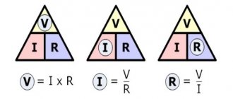
In our example, a light bulb with resistance R and a resistor are connected in series, so the current in the circuit can be found using the formula
And then the voltage across the light bulb is
It turns out that the greater the resistance of the light bulb, the more volts it receives, and the less volts are uselessly lost in the battery. This applies not only to the light bulb and battery, but also to any circuit consisting of a power source and load. The greater the load resistance, the smaller the difference between voltage and emf . If the load resistance is very large, then the voltage is almost equal to the EMF . The resistance of a voltmeter is always very high, so in the circuit in Figure 1 it showed a value of 1.5 V.
Understanding the meaning of EMF is hindered by the fact that we practically do not use this term in everyday life. We say in the store: “Give me a battery with a voltage of 1.5 volts,” although it is correct to say: “Give me a battery with an emf of 1.5 volts.” But that’s how it happened...
Related article: What is the difference between voltage and potential.
—
Did you like the article? Post a link to the site on social networks
Physical meaning of the law
Consumers of electric current together with the current source form a closed electrical circuit. The current passing through the consumer also passes through the current source, which means that in addition to the resistance of the conductor, the current has resistance from the source itself. Thus, the total resistance of the closed circuit will be the sum of the consumer resistance and the source resistance.
The physical meaning of the dependence of the current on the emf of the source and the resistance of the circuit is that the greater the emf, the greater the energy of charge carriers, and therefore the greater the speed of their ordered movement. As the resistance of the circuit increases, the energy and speed of movement of charge carriers, and therefore the magnitude of the current, decrease.
Dependence can be demonstrated experimentally. Consider a circuit consisting of a source, a rheostat and an ammeter. After switching on, a current flows in the circuit, observed on the ammeter; by moving the rheostat slider, we will see that when the external resistance changes, the current will change.
Current and voltage sources
A source is an element that supplies a circuit with electromagnetic energy. This energy is consumed by passive elements of the circuit - it is stored in inductances and capacitances and spent in active resistance. Examples of real sources of electromagnetic energy include generators of constant, sinusoidal and pulse signals of various shapes, signals received from various sensors, antennas of radio receiving devices, power supplies, signals coming from the outputs of electronic devices, etc.
To analyze circuits, it is convenient to introduce idealized sources of two types: a voltage source and a current source, which take into account the main properties of real sources. With the appropriate addition of idealized sources with passive elements, it is possible to convey all the properties of real sources in relation to their external outputs.
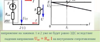
Voltage source. A voltage subsource is understood to be such an element with two terminals (poles), the voltage between which is specified as a certain function of time, regardless of the current supplied to the external circuit. The dependence of voltage on current of an ideal voltage source is shown in Fig. 1.3. Such an idealized source is capable of delivering unlimited power. The most commonly used conventional graphic images of the voltage source are shown in the same figure, where the accepted positive polarity of the source voltage is indicated either by an arrow inside a circle, or by the signs “+”, “-”.
Real signal sources have internal resistances. The internal resistance is connected in series to the voltage source. In Fig. Figure 1.4 shows the current-voltage characteristic and circuit of a real voltage source. For a real source, the output voltage will be equal to
Un = U0 – URin = U0 – In Rin.
From the formula it is clear that the output voltage of a real current source depends on the load current In. The greater the load current, the more the voltage drops across the internal resistance of the source, and a smaller part of the voltage U0 is supplied to the load (output). On the other hand, the greater the internal resistance Rin at a constant load current, the more the voltage drops across it, which leads to a decrease in the voltage at the source output. In electronic circuits, the internal source resistance is often called the output resistance.
In the case of an ideal voltage source, its internal resistance is 0 and the voltage across the load does not depend on the load current. In this case, the load current can increase to infinity if the load resistance tends to 0. In fact, it is impossible to construct an ideal voltage source over the entire range of output current changes. However, in many cases, for a limited range of output current variations, some sources can be considered ideal.
For example, a power supply in the range of operating currents has very low internal resistance, which can be neglected, compared to the load resistance. Or another example, the output impedance of an operational amplifier covered by negative feedback can reach several hundredths of an ohm. This internal resistance can be neglected and the op amp output can be treated as an ideal voltage source within the range of permissible output currents.
Current source. An ideal current source is understood as a circuit element through whose terminals a current flows with a given law of change over time, regardless of the voltage between the terminals. The current-voltage characteristic and conventional graphic images of an ideal current source are shown in Fig. 1.5. The independence of current from voltage means that the internal conductivity of the source into which the current can branch is equal to 0, and the internal resistance is equal to infinity. Current-voltage characteristic and
the circuit of a real current source is shown in Fig. 6. As the voltage across the load increases due to the increase in load resistance, the internal current of the current source increases. In this case, a smaller part of the current I0 flows into the load. The output current In will be equal to
In = I0 – Iin = I0 – Un / Rin.
From the formula it is clear that the greater the internal resistance of the current source, the lower the internal current Iin and the greater part of the current I0 is given to the load. In the limit at Rin = ∞, the entire current I0 is supplied to the load, and the load current will not depend on the voltage across the load. In this case, we are dealing with an ideal current source. So, in an ideal current source, the internal resistance is equal to infinity. In an ideal current source, with an infinite load resistance (open load circuit), there will be an infinite voltage at its terminals.
This is, of course, an idealization - it is impossible to build a current source whose internal resistance is infinite. However, in practice, current sources are used, built on transistors, with internal resistance reaching values of many megohms or more, operating in a limited range of output voltages. Such current sources are widely used in differential and operational amplifier circuits, in the construction of digital-to-analog converters, in transmitting signals through a current loop, etc.
Real voltage and current sources are equivalent. This means that the circuits behave in the same way relative to their terminals, i.e. When analyzing a circuit, the same source can be considered as a real voltage source or a real current source. The equivalence conditions can be obtained from the expression for the voltage of a real voltage source
Un = U0 – In Rin.
Divide the right and left sides of the equation by Rin, we get
Un /Rin = U0 /Rin – In .
Let us introduce the notation U0 /Rin = I0 = const; U0 /Rin = Iin and write the equation in the following form
Iin = I0 - In or I0 = Iin + In.
Moreover, the same voltage Un drops across resistances Rin and Rn, i.e. they are connected in parallel
I0 = Un /Rin + Un /Rn .
From here we come to the circuit of a real current source, shown in Fig. 1.6.
Since the circuits of real voltage and current sources are equivalent, the question arises: when to use one or another source when analyzing a circuit? The answer is simple. Use the type of source that makes it easier to analyze the operation of the circuit. In practice, they often do the following. If the internal resistance of the source is much less than the load resistance, then it is advisable to consider such a source as a voltage source. And to a first approximation, the value of internal resistance can be neglected. If the internal resistance is much greater than the load resistance, then such a source is considered as a current source. And upon initial analysis, it is considered ideal. A more detailed analysis of the circuit takes into account the non-ideality of the current source.
Direct current: 2 current sources
Calculation of voltage drops between different points, determination of currents and voltages in a circuit, including using Kirchhoff’s laws - that’s what awaits us in this article.
Problem 1. In the battery shown in the figure, V, Ohm, V‚ Ohm‚ V, Ohm; Om‚ Om. Find the emf and internal resistance of this battery.
To task 1
We simply add up the internal resistances (connected in series):
To find the EMF, note that the sources are turned on “wrongly”, so the EMF will be equal to
Answer: Om, V.
Task 2. Calculate the emf and internal resistance of a battery consisting of three emf sources (Fig.), if the emf of the sources is 10 V, 20 V, 30 V, respectively, and their internal resistances are the same and equal to 1 Ohm. When connecting sources in parallel, they can be converted into one using the following formulas:
To task 2
Then
Now let's recalculate the series connection of two sources:
Answer: Ohm, V. Problem 3. In a certain circuit there is a section shown in the figure, Ohm, Ohm‚ Ohm, V, V‚ V. Find the current strength in each resistance and potential.
To problem 3
According to Kirchhoff's first law.
Let
Then:
Then the current strength in the branches:
Task 4. Determine the potential difference between the terminals in the circuit shown in the figure, if V, Ohm, Ohm.
To problem 4
The branch resistances are equal
Since the resistances of the branches are equal, the total resistance of both branches
And the current in the unbranched part of the circuit is equal to
This current will be divided exactly in half at a point - again due to the equality of the resistances of the branches. Thus, the currents in the branches are 1 A.
These currents will create voltage drops V, V.
From the figure we can write according to Kirchhoff’s second law:
Answer: B.
Task 5. Find the potential difference at the terminals of each current source, if Ohm, Ohm, Ohm, V.
To problem 5
Let's determine the current in the circuit; to do this, we first determine the total EMF:
The current in the circuit is:
This current will create a voltage drop of:
On :
Then at the terminals of the first source
At the terminals of the second source
Answer: B, B.
Problem 6. The circuit includes three sources of EMF and two resistors (Fig.) Determine the EMF and internal resistance of the equivalent source acting in the circuit, as well as the potential difference between points A and B, if B, B, V, Ohm, Ohm, Ohm , Ohm, Ohm.
To problem 6
We simply add up all the resistances (connected in series):
To find the EMF, note that the sources are turned on “wrongly”, so the EMF will be equal to
The current in the circuit will be equal to:
This current will create a voltage drop:
According to Kirchhoff’s second law, we write:
Answer: B.
Problem 7. The circuit includes three batteries (Fig. 12.62) V, V, V, Ohm, Ohm, Ohm. Find the voltage at the terminals of the first battery.
To problem 7
We simply add up all the resistances (connected in series):
To find the EMF, note that the sources are turned on “wrongly”, so the EMF will be equal to
The current in the circuit will be equal to:
This current will create a voltage drop:
The required voltage is
Answer: B.