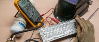
This skill is not useful every day, but it is better to find out in advance how to check the voltage in an outlet with a multimeter and what it should show. In addition to voltage, the electronic tester is capable of measuring current strength and resistance of wires, for which the connection of the plugs on the device must be swapped. Their correct connection must be carefully monitored - if measurements are taken incorrectly, a short circuit will occur.
Why do you need to know the voltage in the outlet?
A modern home is filled with many electrical appliances - kettles, irons, washing machines, refrigerators, TVs, etc. For them to work well and for a long time, they require high-quality electricity, the parameters of which are stable. If the voltage does not correspond to the nominal value, the equipment will overheat and quickly fail. Problems can also occur if there are frequent strong fluctuations in the network.
When a problem arises - the device stops functioning - the first step to eliminating it is to determine the voltage in the outlets. If it is normal, the cause of the breakdown may lie elsewhere - wear, manufacturing defects or improper operation. Therefore, before going to a repair shop, it is worth finding out if everything is in order with the electrical outlet.
Voltage in the outlet - what is it?
In the home networks of all objects in Russia, alternating current flows. Unlike a constant, the direction and magnitude of which do not depend on time, its parameters change with a frequency of 50 Hz (50 oscillations per second). One of the directions of the current is conventionally assumed to be positive, the other - negative.
The voltage at the outlet is AC voltage, which is supplied through street power lines. If the initial potential at substations reaches several thousand volts, then after passing through step-down transformers, the value is reduced to a nominal 220 V, accepted for most networks.
In some cases, a three-phase network system with a voltage of 380 V is installed. This is advisable when there are many points at the site that consume electric current, or powerful equipment is installed. For example, in a house heated by an electric boiler, with a workshop, a heated pool, and a sauna. But in this case, 380 V will only be at the input. And then the branches with different energy consumption are divided into phases - the garage and bathhouse into one, living rooms into another, kitchen with laundry room into a third. This allows you to optimally distribute the voltage between points. Accordingly, the sockets in different rooms will have different potentials - 380 or 220 V.
As a result of lightning strikes, equipment failure, electromagnetic interference, or when connecting a large load, deviations, dips, and overvoltages are observed in the network. They are compensated by appropriate devices along the entire current path, including the tripping of home network protection. Then the internal wiring and household appliances are not exposed to these destructive factors, and the voltage in the outlet remains stable.
In America, Japan and some European countries, current standards differ from Russian ones. Most of their electrical appliances are designed for a voltage of 100-127 V and a frequency of 60 Hz. Manufacturers of multimeters, trying to increase sales of their products, produce universal devices that can be used at various nominal current values. Therefore, modern testers for measuring the characteristics of electrical networks have an expanded scale.
Safety precautions
The multitester is a fairly reliable device from a safety point of view. However, its use still requires compliance with certain rules. The tester has internal protection against excessive loads. However, if the device is not handled correctly, it can quickly fail.
When measuring input AC voltage, it is recommended to adhere to the following rules:
- If the approximate value of the measured voltage is unknown, the switch must be set to the maximum range.
- Do not apply voltage exceeding 750 volts to the input. Otherwise, there is a high probability of destruction of the internal circuit.
Important! Do not touch electrical components without wearing dielectric gloves.
When measuring input DC and AC current, the following rules should be observed:
- If preliminary data on the value of the measured current are not predetermined, the switch is set to the maximum possible range.
- If the LCD display is set to one, the trigger should be placed on the adjacent range in the direction of the higher value.
- Test time when working with the 20-amp range should be no more than 15 seconds. The fact is that there is no fuse for this mode.
When measuring the internal resistance of a circuit, make sure that the power supply is turned off and the capacitors are completely discharged.
You should also adhere to the rules for storing and caring for equipment. Do not apply voltage to the input when the rotary switch is in the Ohm position. It is not recommended to operate the device with the lid open or partially closed.
There is one more rule regarding the proper use of a multimeter. It is not permissible to replace the galvanic element and fuse while the device is running. It is necessary to turn off the multimeter and disconnect all probes.
Permissible voltages in the home network
According to GOST 29322-2014, the standard voltage can reach values of 230 V ± 10%, that is, 207-253 V. The old GOST 13109-97 limited it to lower numbers - 220 V ± 10% = 198-242 V. In this case, it is considered normally acceptable deviation is 5%, and the maximum permissible is 10%.
According to these two standards, the consumer network must provide conditions under which the voltage is not higher than 253 and not lower than 198 V. Within this interval, the potential is normal, that is, the outlet can be either 200 or 250 V.
However, sensitive electrical appliances react negatively to such deviations. A freezer, light bulb, or water pump operates in an unusual manner and its service life may be significantly reduced. Asynchronous motors are even more capricious; when the voltage differs by only 5% from the nominal value, they overheat and quickly fail.
If you notice frequent power surges, you need to complain to local organizations: the electric grid company, the housing and communal services department, Rospotrebnadzor or the housing inspection. You can submit your application online from the comfort of your home. In addition to the fact that measures must be taken to eliminate network deficiencies, electricity charges may be revised downward. The law prescribes a 0.15% discount for each hour of supply of a low-quality resource, and in some cases it is allowed to reduce the payment for electricity to 0.
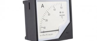
Multimeter scale markings
Analog instruments with arrows have scales, which are divided into named and conditional. Named scales are graded with measurable indicators. Conventional scales are used in instruments that are capable of measuring many parameters.
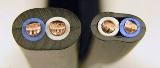
Which wires are best to use for wiring in an apartment. Great comparison article here.
To find a numerical indicator that is measured by a device with a conventional scale, it is necessary to multiply the value of one scale division by the number of divisions on a given scale up to the interval where the arrow appears.
In addition, to determine the value of one division, it is necessary to establish the difference between the indicators of nearby divisions with numbers and divide by the number of divisions between them.
Multimeter markings
The positions of the linear or angular intervals between the surrounding scale marks, and the measured indicators, are distinguished by devices of uniform and non-uniform types.
What to do if a person is electrocuted? Everyone should know this, everyone should read it!
For accurate results, a model with a uniform scale is preferred. This scale will be uniform if the ratio of the largest number to the smallest does not exceed the reading of 1.3 with a constant division value.
Near the scale on the front panel of the measuring device, the existing marking parameters are listed:
- measure of value;
- GOST, according to which the multimeter is manufactured;
- tester device; degree of protection of the device from the influence of external magnetically active and electrical environments;
- accuracy class.
In addition, it is indicated:
- tool category according to operating requirements;
- functional location of the multimeter;
- number of phases and type of current;
- experimental voltage for the reliability of electrical insulation of current-carrying elements of the invention;
- the location of the tester in comparison with the earth's magnetic field;
- the year of publishing;
- view;
- code;
- factory number and other indicators.
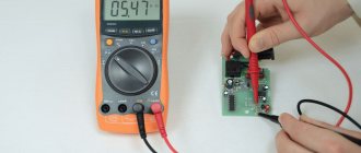
How to check the voltage with a multimeter in a 220 volt outlet: step-by-step instructions
One of the most affordable and common devices for examining a circuit is a mobile multimeter. It measures not only voltage, but also other quantities - current, resistance, capacitance of capacitors. Some models can determine temperature, transistor gain, alternating current frequency, conduct diode tests, and continuity tests.
Mode selection
To set the desired mode and range, special icons are applied to the device body. The AC voltage measurement is carried out with the switch position in the sector marked V˜ (it is important not to confuse it with direct current, which is determined in another segment marked V-).
Now you need to select the desired measurement limit. For all Russian networks, it is recommended to set the range to 750 V, since the voltage exceeds 200 V. If you set the lever to a lower level, the voltage will appear on the display as one.
For current measurements, a connection error can become critical. The fuses will fail and the device will have to be repaired. Therefore, you need to choose a range with a margin, especially if you are not sure of the upper limits of the current parameters.
Connecting probes
Electrical appliances or sections of the circuit are connected to the multimeter using 2 red and black conductors. The ends of the probes with plugs are inserted into the holes on the tester, and those with pointed rods are thrown onto the contacts.
There can be from 2 to 4 connectors depending on the set of capabilities and functions:
- The output marked COM is “base”, “zero”, “ground”. A black probe is always attached to it.
- VΩmA - connector for measuring voltage, resistance and current up to 200 mA, red probe.
- 10A - hole for measuring current up to 10 A, red probe.
The voltage in the outlet is determined when the circuit is closed, but, unlike the current, without a load. To carry out measurements, the probes must be inserted into the appropriate connectors - black in COM, red in VΩmA.
Voltage measurement
All work on electrical equipment carries potential danger. Simple rules will help you avoid it:
- do not touch open conductors;
- do not hold the probes with both hands, so that if the circuit is accidentally closed, the current does not pass through the entire body;
- If the tips are close together, use an alligator clip during measurement.
You need to take the probes in one hand, insert the ends into the holes in the socket and wait until the readings stabilize. Moreover, it does not matter which of them will be in phase and which will be at zero. The multimeter will show the absolute value of the potential in volts.
Types of device
A multimeter (multitester) is a device for measuring a variety of parameters of the electrical network, as well as other elements powered from it.
The device allows you to accurately determine network characteristics such as voltage, current, resistance and a number of other data. The multitester also makes it possible to test transistors, test cables and wires, test diodes, etc.
From the point of view of the design of the device itself, analogue and digital multimeters are distinguished. The devices differ in functional characteristics, accuracy of operation, workmanship, and configuration.
Analog testers are often called voltmeters or ammeters, since such devices are usually configured to perform 2-3 functions and nothing more. Analog devices show measurement results with a regular arrow on a scale. This technique is quite difficult to operate and requires some experience. A beginner will not immediately understand all the available scales in order to determine the final value of electrical data. In addition, analog equipment is not able to fix the arrow in position, which makes it difficult to work with.
The digital device displays measurement results in electronic form (on a liquid crystal monitor). The device is easy to operate and dramatically reduces the participation of the human factor, and therefore errors in measurements. The simplicity and accuracy of readings have made digital devices the most popular on the market.
Screwdriver indicator
To determine the phase in the socket, you can use a tester screwdriver. This is a small device in the form of a regular screwdriver with a transparent handle, which has a built-in LED light bulb. When the operating circuit is closed, it lights up, indicating the presence of voltage. At the end of the handle there is a contact plate for determining 0.
Test rules:
- Holding the screwdriver carefully in your hand, insert the tip into the socket of the socket.
- If there is phase, the LED indicator inside the transparent handle will light up. If there is no light, then this is a neutral conductor.
- To check if there is current in the circuit, place your finger on the end. The circuit will close and the indicator will work.
Using such an indicator screwdriver it is impossible to set the numerical value of the potential, but it is quite enough to determine a break. A screwdriver with advanced functionality has much more capabilities. This miniature device has a switch with 3 modes:
- O - for contact determination of voltage, if present, the red diode lights up;
- L - for contactless operation, when approaching a phase the green light is on;
- N - for working using a non-contact method with high sensitivity, in addition to the green diode, the signal is generated by an audible buzzer.
The choice of mode is determined by the possibility of open contact with conductors, as well as the circuit resistance. For O it should be no more than 5 mOhm, for L and H - 50 and 100 mOhm, respectively.
There is a metal plate on the side of the indicator screwdriver body. During contact work, you do not need to touch it to determine the phase. If a continuity test is performed, then in the O mode the sting touches the contacts, and the finger is placed on the plate, forming a jumper in the circuit. If the circuit is intact, the red indicator lights up. In this way, not only sockets are checked, but also incandescent lamps, heating elements, switches and other devices.
Measuring AC current with a voltmeter
If you need to measure the strength of alternating current, but you only have a budget multimeter at hand, which does not have such functionality, then you can get out of the situation by using the measurement method using a shunt. Its meaning is reflected by the formula I = U / R, Where I is the current strength that needs to be found, U is the voltage in the local section of the conductor, and R is the resistance of this section. From the formula it is clear that if R is equal to one, then the current strength in the circuit section will be equal to the voltage.
To measure, you need to find a conductor with a resistance of 1 ohm - this can be a fairly long wire from a transformer or a piece of spiral from an electric stove. Wire resistance, i.e. its length is adjusted by the tester in the appropriate test mode.
The result is the following circuit (incandescent lamp as a load):
- From the first connector of the socket, the wire goes to the beginning of the shunt, and one of the multimeter probes is connected here.
- The second probe of the multimeter is connected to the end of the shunt and from this point the wire goes to the first contact of the lamp base.
- From the second contact of the lamp base, the wire goes to the second connector of the socket.
The multimeter is set to AC VOLTAGE MEASUREMENT MODE. It is connected in parallel to the shunt, so all the rules are followed. When the power is turned on, it will show a voltage equal to the current passing through the shunt, which in turn is the same as the load.
This measurement method is clearly shown in the video:
Determining the location of the break
An indicator screwdriver will help you quickly determine a break even without contact with the circuit. To do this, just bring a screwdriver to the wires. It responds to the magnetic field that is present around the conductor carrying alternating current. If the indicator lights up, there is no break; otherwise, damage is detected.
Another situation is possible when there should be no current in this conductor. But if the LED and buzzer are triggered, then the electrical wiring has been installed incorrectly. This happens, for example, when connecting chandeliers. In this case, the lamp does not light, but is energized due to errors by the electrician. To replace a burnt-out light bulb and avoid electric shock, you need to turn off this branch through the circuit breaker.
Wire resistance measurement
This is the simplest mode of operation - essentially you need to take a wire, for which you need to measure the resistance and touch the ends of the multimeter with the probes.
Resistance measurement occurs thanks to the power source that is inside the multimeter - the device measures its voltage and current in the circuit, and then calculates the resistance using Ohm's law.
There are two nuances when measuring resistance:
- The multimeter shows the sum of the resistances of the wire being measured along with the probes that touch it. If exact values are needed, then the probe wires must initially be measured and then the result obtained should be subtracted from the total.
- It is difficult to estimate in advance the approximate resistance of the wire, so it is advisable to make measurements by reducing the sensitivity of the device.
If the device stops working
Sometimes it happens that a drill or light connected through an extension cord suddenly stops working. How to determine what was the cause - a malfunction of the socket, extension cord or the device itself?
Carrying out a check with an indicator screwdriver at hand is very simple:
- First, the outlet is inspected. The presence of voltage and the location of the sockets with 0 and phase are determined. This eliminates problems with the socket.
- Then the screwdriver is brought in turn to each section of the circuit - the extension cord and the non-working device.
- In case of integrity of the conductor connected to the phase, an indicator signal will follow.
- The next step is to turn the extension cord plug over and insert it back into the socket, while 0 and phase are swapped.
- The wires are tested again.
- If there is no signal, it will be clear which area is damaged.
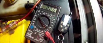
If a break is not detected, it means that there is not enough voltage in the network itself. You can find out using a multimeter, which will show the exact numerical value.
Connecting probes to a multitester
Probes are connectors for measuring the parameters of electrical components and sections of an electrical circuit. The devices help to combine the multimeter connectors with other outputs. The probes look like a metal rod insulated with plastic. At one end of the probe there is a wire with a connector for connecting to connectors (20A, A, VΩ, COM).
Note! To use all the capabilities of the multitester, you need to have an additional arsenal of probes, where toothed clamps are used instead of a rod.
Most of the measuring equipment comes from China. Some products are quite high quality, but there are also low-quality products. As a rule, manufacturers of cheap products skimp on materials for probes, as a result of which they quickly become unusable.
If desired, you can make the probes yourself. The parts you need are easy to find at your local radio market or radio supply store. As insulation, you can use available materials, for example, empty plastic ampoules or shells from ballpoint pens.
How to measure three-phase voltage
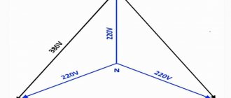
A three-phase outlet is different from a single-phase outlet. It contains not 2 connectors, but 4 or 5 - A, B, C for each phase, N for neutral and in some models PE for grounding. If connected correctly, the voltage between the phases and the working zero will be 220 V (it is called phase voltage), and between pairs of phases - 380 V (linear voltage).
To check the serviceability of the outlet, you will have to perform 6 measurements:
- A-N;
- B-N;
- C-N;
- A-B;
- A-C;
- S-V.
You should get 3 results of 220 V and 3 of 380 V. If you need to check the voltage between zero and ground, another N-PE measurement is made. In a healthy system it is equal to or very close to 0.
As a result
Even a budget universal measuring device - a multimeter - allows you to take measurements within a fairly wide range, sufficient for home use. But when buying a device, you need to at least have a general idea of what purposes it will be used for - it may be better to overpay a little, but as a result, have a tester on hand that can perform any task assigned to it. Also, before using it, it would not hurt to at least in general refresh your memory of the basics of constructing electrical circuits and using electrical measuring instruments in them.