- home
- >Manufacture of generators
The main indicator of a generator is voltage, and knowing the voltage, you can calculate all other parameters, such as the battery charging current and the power of the generator as a whole. A generator is usually built to charge batteries, and for this we will try to calculate the generator. The voltage of the generator coils depends on the number of turns in the coils, on the magnetic induction of the magnets, and on the speed at which the magnetic field changes. Simply put, the faster the magnets move past the coils, the higher the voltage.
To calculate the generator voltage we will use a simple formula, it is very simple and should not cause problems. You can read more details with an example here - Calculation of the EMF of a generator. The phases and connections of the coils will be discussed below, but for now let’s look at the generator voltage.
Formula E=B V L
where: E is the generator voltage (V). B-magnetic induction of magnets (T). V-speed of movement of magnets (m/s). L-active conductor length (m).
With the letter E is the voltage of the generator, which we need to calculate, and then the letter B - which is not known, since we do not know what the magnetic induction of the magnets is. But if you search the search engine and read the forums, you can find out that the magnetic induction of neodymium magnets is about 1.25 T, of course it is different for different brands of magnets, but this is the average value. It is also known that the further away from the magnet, the less magnetic induction. In general, if, in the case of manufacturing a disk generator, the distance between the magnets on opposite disks is equal to the thickness of the magnets, then the magnetic induction will be approximately 1.0 T; if the distance is greater, then naturally the magnetic field will be weaker. If, for example, you have magnets 10 mm thick, and you make the distance between the magnets 10 mm, then the induction will be somewhere around 1.0 T, and the stator in this case will be no more than 8 mm thick, and 1 mm for the gaps. If the distance is, say, 12-14 mm, then the magnetic induction will drop to 0.8-0.7 T and below.
For generators with iron, the principle is the same, but the thickness of the magnets can be different, some use magnets with a thickness of 10-15mm, although for a magnetic induction of 1.0T a magnet thickness of 3-4mm is sufficient. Another important thing is the thickness - the magnetic transmittance of the stator, on the teeth of which the coils are wound. If you go too far with the thickness of the magnets, the stator will not be able to close the entire magnetic field and it will come out, and iron will be magnetized to the stator from the outside. That is, this is a loss of the magnetic field and there is no point in using too powerful magnets since part of the magnetic field will not be used. Everything, of course, depends on specific conditions, but if the magnetic induction is not known, then it is better to take it as 0.8-1 T.
Let's return to the formula, V is the speed of movement of the magnets, it is very simple to calculate. For example, if the diameter of the rotor with magnets is 20 cm, then 20 * 3.14 = 62.8 cm. That is, it turns out that in one revolution the magnets travel a distance of 62.8 cm or 0.62 meters. If the rotor diameter is 8cm, then similarly 8*3.14=25.12cm or 0.25m.
L is the active length of the conductor, that is, this is the length of the copper wire that falls under the magnets, because it is only that section of the wire that generates electricity that falls under the magnetic field of the magnets. For disk axial generators, the length of the active conductor is equal to the length of the magnets. For example, if you have round magnets measuring 30*10mm, then L=30mm, but if rectangular magnets measuring 50*30*10mm, then L=50mm. For generators with an iron stator, the active length of the conductor is equal to the width of the stator.
Active conductor length
Active conductor length, calculation of generator coils
Now let's try to calculate the generator voltage, but first we'll deal with the generator coils
Generators come in both single-phase and three-phase. As a rule, beginners make single-phase generators considering them simpler, but single-phase ones hum during operation, since the number of magnets and coils in such generators is the same. And it turns out that when the magnets run into the coils, the coils resist this and repel the magnets. As a result, there seems to be a peak in resistance and a decline, which causes buzzing and vibration. Three-phase ones are designed differently, there is a 2/3 displacement of the coils relative to the magnets, and due to this the load is evenly distributed, which makes the vibration much lower. Also, the power characteristics are somewhat better, and the circuit is not much complicated.
Below is a connection diagram for a single-phase generator
Security measures
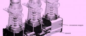
When diagnosing a module, it is recommended to adhere to the following rules:
- do not close contacts;
- do not allow water to enter;
- store the battery separately;
- monitor the tightness of the structure;
- check the voltage level.
When removing the generator, the components are checked. Attention is paid to the operating rules according to the instructions. The installations operate in certain modes, and the main characteristics are assessed. Modules are afraid of salt and liquids. Installation of the generator must be carried out by a specialist.
If you connect the generator to a car, you need to check the power rectifier. It is necessary to remove the exciter windings, as well as the phase. The voltage regulator is checked separately. During installation, it is prohibited to check until fully connected.
The concept of a voltage generator is described in detail above. The basic operating principle and characteristics are described. The amperage, rotation speed and connection diagram are taken into account.
Coil connection
connection of coils of a single-phase generator Coils of a single-phase generator are connected like this
, the beginning of the first to the output (diode bridge), and the end is connected to the end of the second coil, the beginning of the second to the beginning of the third, the end of the third to the end of the fourth, the beginning of the fourth to the beginning of the fifth coil, and so on until last reel.
Connection of three-phase generator coils
Device Description
The simplest current generator is a setup with a wire coil. The branches intersect with each other and during movement the electrons begin to move. The action of the elements is carried out relative to the poles of the magnets. The main task is to indicate electric current. If we look at history, the following varieties previously existed:
- Jedlik dynamo;
- Faraday disk;
- Dynamo machine;
- electrical modules with rotation.
Dynamo machine
Coil connection
connection of the coils of a three-phase generator, in the figure there is a stator consisting of 15 coils. The coils of a three-phase generator are connected like this
: The beginning of the first coil with the end of the fourth, and the beginning of the fourth with the end of the seventh, the beginning of the seventh with the end of the tenth, the beginning of the tenth with the end of the thirteenth, and the beginning of the thirteenth with exit along with the end of the first. The remaining two phases are similar starting from the second coil, and the third phase from the third. In the figure, the stator consists of 15 coils, and the disks should have 10 magnets. If the stator consists of 9 coils, then there are three coils per phase, and the disks can have either six pairs of magnets or 12 pairs.
Let's return to the formula E=B·V·L
. For example, it is planned to wind 18 coils with 1.0 mm wire, and 80 turns are placed in the coil, which means that in total we have 18 * 80 = 1440 turns. If the generator is single-phase, then we calculate this for all coils, and if it is three-phase, then we will take coils of one phase, in this case six coils in a phase, and then we will calculate the data for a star or triangle connection. I will consider three-phase, so I take six coils 80 * 6 = 480 turns.
Our magnets, for example, are 30*10mm (12 pieces per disk), which means the active length of the conductor is 0.03m; if the stator is iron, then the width of the stator is taken. For example, we have disks with magnets with a diameter of 20 cm, but we need to take the diameter at the center of the magnets, which means minus 1.5 cm in a circle and that’s 20-3 cm = 17 * 3.14 = 53.38 cm or 0.53 m. I would like to remind you that the thickness of the iron disks must be no less than the thickness of the magnets, otherwise the magnetic field will go beyond the iron and will not participate in the generation of electricity and the magnetic induction will be lower, and if you have, for example, the rotor of an asynchronous motor, then after grooving it is advisable to put on a metal sleeve and glue magnets onto it, or grind out an all-metal rotor, this way the magnets will be used more efficiently and you can either get more power or save on the thickness of the magnets.
And so now we have the necessary data to calculate the generator voltage, for example, at 60 rpm. Let's take the magnetic induction equal to 1 T. The speed of movement of the magnets per revolution is 0.53 m, which means that at 60 rpm there will be 1 rpm, that is, 0.53 m/s is the speed of movement of the magnets. The active length of the conductor is also known to us and is equal to 0.03 m. Then 0.03m needs to be multiplied by the number of turns in the coil (80) and the number of coils (6), and you get 0.03*480=14.4m.
Now we represent the values in the formula E=B(1T)*V(0.53m)*L(14.4m), it turns out E=7.632V. In general, at 60 rpm the phase voltage is 7.6 volts. The generator voltage increases linearly depending on the speed, which means that at 120 rpm it will be 15.2 volts, and at 240 rpm it will be 30.4 volts. And at 300 rpm there will be 38.0 volts. Charging will start at 120 rpm if you connect the generator phases with a triangle. When connected by a star, the generator voltage will be 1.7 times higher, which means charging will begin even earlier, at 90 rpm.
But if you draw a virtual stator with coils and magnets, you can see that the magnet does not completely cover the coil and 30% of the active zone does not overlap no matter how the magnet is standing, which means that 30% is not involved in generating voltage and this must be taken into account. It often happens that the magnet covers only half of the coil, and this means that only half of the turns are involved in generating electricity. This means that in our case the voltage will be 30% lower than it turned out, that is, not E=7.632V, but E=5V.
Now let's talk about the generator current, its resistance and star-delta connection
We can now determine the voltage and adjust the start of charging to the propeller of the wind generator, so that the propeller can unwind and charging begins in a weak wind.
But charging is carried out with current in amperes, and the current strength depends on the resistance of the coils and the load as a whole (wires and battery). The lower the resistance, the higher the charging current and the lower the heating losses; therefore, the resistance of the generator winding should be made as small as possible. In our generator, consisting of 18 coils, there are only 18 * 80 = 1440 turns, which is 480 turns per phase. To find out the phase resistance you need to find out the length of the wire in the phase and its cross-section. The average length of one turn is approximately 0.08m, which means 0.08*480=38.4m. The resistance of one meter of copper wire with a cross section of 1 mm is 0.0224 Ohm. Next 38.4*0.0224=0.86 Ohm.
Theoretical part
The basic principle of operation of the alternator
Let's start with the most basic - alternating current differs from direct current in that it changes its direction of movement with some periodicity. It also changes the value, which we will talk about in more detail later.
After a certain period of time, which we will call “T”, the values of the current parameters are repeated, which can be depicted on the graph as a sinusoid - a wavy line passing with the same amplitude through the central line.
Basic principles
So, the purpose and design of alternating current generators, previously called an alternator, is to convert kinetic energy, that is, mechanical, into electrical energy. The vast majority of modern generators use a rotating magnetic field.
- Such devices operate due to electromagnetic induction, when when a coil of conductive material (usually copper wire) rotates in a magnetic field, an electromotive force (EMF) arises in it.
- The current begins to form at the moment when the conductors begin to cross the magnetic lines of the force field.
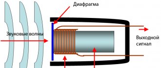
The structure of the simplest electromagnetic generator
- Moreover, the peak value of the EMF in the conductor is achieved when it passes the main poles of the magnetic field. At those moments when they slide along the lines of force, induction does not occur and the emf drops to zero. Take a look at any of the diagrams presented - the first state will be observed when the frame takes a vertical position, and the second - when it is horizontal.
Alternating current generator - how it works
- To better understand the ongoing processes, you need to remember the rule of the right hand, studied by everyone in school, but few remember. Its essence lies in the fact that if you position your right hand so that the magnetic field lines enter it from the palm, the thumb moved to the side will indicate the direction of movement of the conductor, and the remaining fingers will indicate the direction of the EMF arising in it.
- Take a look at the diagram above, position "a". At this moment, the emf in the frame is zero. The arrows show the direction of its movement - part of frame A moves towards the north pole of the magnet, and B - towards the south, reaching which the EMF will be maximum. Applying the right-hand rule described above, we see that the current begins to flow in part “B” towards us, and in part “A” - away from us.
- The frame rotates further and the current in the circuit begins to fall until the frame again takes a horizontal position (c).
- Further rotation leads to the fact that the current begins to flow in the opposite direction, since parts of the frame have swapped places when compared with the initial position.
After half a revolution, everything will return to its original state and the cycle will repeat again. As a result, we found that during the complete revolution of the frame, the current increased twice to a maximum and dropped to zero, and once changed its direction relative to the initial movement.
Alternating current
The current frequency was named in his honor
It is generally accepted that the duration of the circulation period is 1 second, and the number of periods “T” is the frequency of the electric current. In standard electrical networks in Russia and Europe, in one second the current changes its direction 50 times - 50 periods per second.
In electronics, one such period is designated by a special unit, named after the German physicist G. Hertz. That is, in the given example of Russian networks, the current frequency is 50 hertz.
In general, alternating current has found very wide application in electronics due to the fact that: the magnitude of its voltage is very easy to change using transformers that do not have moving parts; it can always be converted to direct current; the design of such generators is much more reliable and simpler than for generating direct current.
The most powerful generators installed at the Pushkinskaya hydroelectric station
Copper Wire Resistance Table
Now we know the phase resistance, which is 0.86 Ohm. If you connect the generator with a star, then the total resistance of the generator will increase by 1.7, and so will the voltage, and if with a triangle, then the total resistance will remain equal to one phase, and the voltage will also be equal to the phase. With a star, the resistance will become 0.86*1.7=1.46 Ohm.
To find out what the battery charging current will be, you need to know the generator voltage and its resistance, which we already know. To calculate, you need to subtract the generator voltage from the no-load voltage of the generator, and divide the resulting amount by the resistance, and you get the charging current. For example, when connected by a star at 120 rpm, the idle voltage is 10V * 1.7 = 17 volts. Then from 17 volts we subtract the battery voltage of 17-13 volts and get a difference of 4 volts, divide by the resistance of 1.46 Ohms, and get 4: 1.46 = 2.7 Amperes. And so you can calculate the current strength at each generator speed, and to get the charging power you need to multiply amperes by volts, in this case 2.7*13=35.1 watt*h. And already at 240 rpm the voltage at idle will be twice as high, since it increases linearly, then 20V-13 = 7: 1.46 = 4.7 Amperes.
But here, not only the resistance of the generator itself plays a role, but also the resistance of the wire from the generator to the battery, the resistance of the diode bridge, on which the voltage drops to 1 volt, and the resistance of the battery itself. All this can be calculated, but it is quite difficult. The resistance of the generator also changes during operation, so the amount of total losses can be up to 50% of the power, and as a result, the charging current can be half the calculated one. And since it is difficult to take everything into account, on average you can reduce losses by 30%, which means that the battery will actually receive a current not of 4.7 Amperes at 240 rpm, but much lower, about 3.5-4 Amperes.
Such a calculation gives a rough idea of the future generator, but it’s still better than doing whatever it takes without taking anything into account, and then being surprised that either the voltage is too low or high, or the resistance is too high and the charging current is ridiculous. Having calculated my generators, I was convinced of the validity of this generator calculation.
When calculating the generator, you need to take into account that it will be rotated by the wind wheel of the wind generator, and the wind wheel has its own speed, and the generator must be at least approximately made to fit the future propeller. If it is a vertical windmill, then its wind wheel rotates very slowly compared to a horizontal propeller. And in this regard, it is necessary that charging begins at very low generator speeds. In order for charging to start early, the voltage must be higher than the battery voltage, hence it is necessary to have as many turns as possible in the coils. But the more turns, the longer the wire, and therefore the resistance, and the resistance determines the strength of the charging current. As a result, in order for the generator to be powerful and charging to begin early, it needs to be calculated so that there is both power and the wind wheel is not overloaded - otherwise it will not reach its speed and gain power.
With a horizontal propeller, the generator needed is not as large and material-intensive as for a vertical one; for horizontal propellers, the speed is on average 5 times higher, which is why the generator needed is five times smaller and the same amount cheaper. Calculations of wind turbine wheels are available in other articles from the section “Calculations of wind turbines”. I advise you to familiarize yourself with this material, since a wind generator is a single mechanism and its components must be suitable in parameters for each other, otherwise either the propeller is too powerful and low-speed or the generator is too powerful, and such a windmill will be of little use.
AC voltage
\[ u = NBS ω \sin(ωt) \]
Alternating voltage The induction voltage changes over time according to a sinusoidal law. During the period it changes sign twice. That's why it is called alternating voltage.
The amplitude, or maximum value of the induction voltage, is determined by the formula
\[ U_{m}= NBSω \]
Then for the instantaneous voltage we have
\[ u = U_{m} \sin(ωt) \]
\[ u = U_{m} \sin(2πft) \]
\[ u = U_{m} \sin(2π\frac{t}{T}) \]
The quantity ω=2πf is called the angular frequency.
The frequency of the alternating current of the industrial network is f = 50 Hz, and accordingly ω = 100π 1/s.
Generator drawing
Preliminary drawing of the generator to find out what size the coils will be.
Since we have 12 magnets on the disks, then 360:12 = 30, it turns out that the sectors for the magnets are divided by 30 degrees. We have 18 coils, so 360:18 = 20, that is, a 20-degree sector of the coil. A coil should fit in a 20 degree sector, the winding width is 10mm, and the thickness of the stator is 8mm, which means wires with a diameter of 1mm will fit 10*8:1=80 turns. If you wind it with 1.5mm wire, then 10*8:1.5=53 turns will fit. And if the wire diameter is 2mm, then accordingly 80*8*2=40 turns.
Specifications
When considering a simple voltage generator, you need to consider the following indicators:
- rated power;
- frequency;
- current overload;
- number of poles.
When considering generators, experts pay attention to amperes. To control it, power regulators are used. In domestic cars the indicator is at around 55 amperes.
Voltage measurement
Coil dimensions
To fit the generator to the wind wheel, or vice versa, then the wind wheel to the generator, you need to calculate the power of the generator at different speeds, for example, at 120 rpm when the battery starts charging and the load on the wind wheel begins, and then at 180,240,300,360,420,480,540,600 rpm.
Based on the above calculated data, we received 17 volts at 120 rpm, our resistance is 1.46 Ohm. more accurate data will be if you measure the voltage during charging in real time, but for low current I took the battery voltage to be 13 volts, and then proceeded from a voltage of 14 volts. As a result, the following calculations were obtained below, but at higher speeds with a large difference between the no-load voltage and the voltage when charging the battery, the efficiency of the generator will drop and the charging current again will not be so large, although the generator will load the propeller at higher power, the losses will be heating of coils and wires. In general, the charging current will be lower by another 10-20%.
at 120 rpm - 17-13=4:1.46=2.7A*13=35 watts at 180 rpm - 25.5-14=11.5:1.46=7.8A*14=110 watts at 240 rpm - 34-14=20:1.46 =13.6A*14=190 watts at 300rpm - 42.5-14=28.5:1.46=19.5A*14=273watts at 360rpm - 51-14=37:1.46=25.3A*14=354watts at 420rpm - 59-14=45:1.46=31A*14=436watts at 480rpm - 68-14=54:1.46=36.9A*14=516watts at 600rpm - 85-14=71:1.46=48.6A*14= 680watt
But when calculating, it is advisable to make the wind wheel 30% more powerful than the design data of the generator, and so that at low speeds the wind wheel is slightly more powerful than the generator. We have 35 watts from the generator at 120 rpm, which means the wind wheel should have a power of about 40-50 watts at 120 rpm. If the wind wheel is weaker, the generator will not allow it to spin up to its speed and, as a result, the speed will be lower and the power will also be lower. For more information about wind wheel calculations, see the articles in the section, everything is there.