In the article we will describe the shaft of an electric motor, its main parameters and indicators. The part is an important component of the engine; it is by its characteristics that all the basic parameters of the power units are determined. Let's consider this issue more specifically.
Stator shaft
One of the tasks of an electric motor is to transfer force from the working unit to the actuators. The task is, in principle, not difficult, but it requires the presence of a connecting link in the motor design. In most modern devices, such a part is a rotor with connecting ends. One of these elements has the shape of a shaft and extends beyond the engine casing. It is this component that is indispensable in the layout of an electric motor and largely determines its parameters. Let's look at how exactly this happens next.
Parameter conventions
Symbols according to GOST overall dimensions of electric motors of the AIR, 4AM brands:
- h – shaft rotation height or electric motor size. Height from the center of the shaft axis to the ground. Important connecting size of the AIR when assembling the unit and centering
- l30*h31*d24 – length, height, width of the AIR electric motor, dimensions. Necessary for calculating the cost of delivery and the required space during transportation
- m – weight of the electric motor, mass. Needed to calculate transport costs and strength of materials
- d1 – shaft diameter. Overall connection size of the AIR required when aggregating with other equipment or selecting a coupling half
- d20 – width, mounting diameter of the flange.
- d22 – diameter of flange holes. Overall dimensions of a flanged electric motor of the AIR type for the manufacture or selection of a counter flange
- l10 and b10 – the distance between the mounting holes on the motor feet. Important overall and installation dimensions required when mounting the electric motor to a frame or platform
- L1 – shaft length
- b1 – key width. The size required for the manufacture of the coupling half
Mounting design – flange, feet, combined
Connection and dimensional drawing of the installation design of the AIR electric motor on feet (IM 1081), feet-flange (IM 2081), clean flange (IM 3081).
Drawing of a foot-mounted engine
Drawing IM2081, IM3081 (feet-flange)
Designation - marking of motor windings
According to GOST 26772-85, the windings of three-phase asynchronous motors must be marked with the letters:
According to the old standard, the designation was slightly different:
Even earlier, one could find the inscriptions N1-K1 (beginning-end of winding No. 1), N2-K2, N3-K3.
On some engines, to make it easier to recognize the ends of the windings, they are brought out from different holes on one side or the other. Like in the photo below.
But you cannot always trust such conclusions. Therefore, it never hurts to check everything manually.
If there are no marks or letters on the barno, and you don’t know where your winding starts and where it ends, read the instructions under the spoiler.
2 methods for determining the beginning and end of motor windings (click on the plus sign to expand)
Take a multimeter as an assistant and set it to resistance measurement mode.
With one probe, touch any of the six terminals, and with the other, alternately touch the remaining five wires, thereby looking for the corresponding pair.
When it is located on the multimeter display, a number should appear showing a certain resistance in Ohms.
In other cases, with other wires, the resistance will be equal to infinity (break).
Mark this winding with tags and move on to the remaining wires. In this simple way, you can “ring out” the ends of all windings in just one minute.
However, that's not all. The main problem is that you do not yet know which of the two terminals is the beginning of the winding and which is its end.
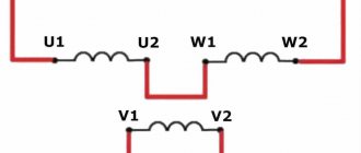
In order to find out, connect two terminals from different windings to each other. That is, we connect the conditional beginning V1 of the first winding with the conditional end of the second winding - U2.
At the same time, you do not yet have accurate information about whether this is the beginning or the end. You marked them this way for yourself in order to make subsequent measurements.
The other ends of these two windings (U1 and V2) are supplied with an alternating voltage of 220V or less. It depends on what voltage your engine is designed for.
The point of this whole action is to measure what voltage appears at the ends of the third winding W1-W2. This is the so-called transformation method.
If there is some value between W1-W2 (10-15V or more), then the first two windings are turned on in agreement, that is, correctly. You guessed all the signed ends V1-V2, U1-U2 correctly.
There is no need to change the tags on them.
If the voltage between W1-W2 is very small or does not exist at all, then it turns out that you connected the first two windings in an opposite circuit (incorrectly). The tags on one of the windings will have to be swapped.
Having dealt with two phases, we move on to the third. The procedure is the same here. Connect the conditional beginning and end of W1 and U2 to each other, and supply 220V to U1 and W2.
Take measurements between terminals V1 and V2. If you guessed right, the engine may even start on two phases, or at least there will be several volts between V1 and V2.
If not, then simply swap tags W1 and W2.
The second method of determining the beginning and end of the windings is even simpler.
First, find three different windings, as indicated above. Connect them in series (the conditional end of the first with the beginning of the second U2-V1, and the end of the second with the beginning of the third V2-W1).
Apply a voltage of 220V to the two remaining terminals U1-W2. After this, alternately bring the light bulb to the ends of each of the windings (U1-U2, V1-V2, W1-W2).
If it burns everywhere with the same brightness, then you guessed right with all the conclusions.
If the brightness differs, this indicates that this winding is inverted in relation to the other two.
The tags on it need to be swapped. In fact, according to TB, it has long been prohibited to work with a light bulb as a control, so instead, it is better to use a multimeter with a voltage measurement function.
Shaft rotation direction
This value is important for avoiding errors during the operation of the shaft and preventing its rotation in the opposite direction from the specified direction. As a rule, arrows are marked on motor housings or drive parts indicating the direction of rotation of the motor.
Shaft rotation pattern clockwise
But, if this information is not on the body or in the documents, then you can determine it yourself; now we will describe how. The first thing to consider before starting is that the search for direction is carried out on the side on which the only end of the shaft is located. If the design involves 2 ends, then determining the moment of rotation must begin from the side of the shaft with a larger diameter.
Based on GOST No. 2672-85, we point out that the movement of the shaft to the right side is fully consistent with clockwise rotation of the part. If we talk about the most popular motors powered by three-phase networks and squirrel-cage rotors, then their shaft rotation to the right will be carried out differently. This occurs if the sequence of phases transmitting voltage to the ends of the stator windings fully corresponds to the sequence of their markings. That is, everything should go one by one in alphabetical order - U1, V1, W1.
Right-hand turns
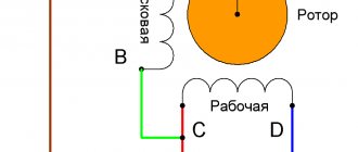
If we are dealing with single-phase motors with squirrel-cage rotors, then the component rotates clockwise when a phase is supplied to the end of the working windings.
Connection for right rotation
When there is a need to change the direction of shaft rotations in motors with three-phase motors, then steps should be taken to change the main direction step by step.
Algorithm for changing direction of movement:
- disconnecting the engine from the power source;
- removing the cover from the terminal box;
- swap the cores of the power cable according to a certain pattern: the core with black insulation L3 is now connected to pin V1. The brown wire L2 is connected to the contact element W1
Reconnect to left
Implementation of reverse
For single-phase electric motors, this possibility is realized by reconnecting the phase to the original contacts of the working windings. Also, you can implement the possibility of reconnection using a 3-pin switch.
Shaft rotation counterclockwise
How to determine power?
There are several ways to determine the power of an electric motor: by shaft diameter, by size and length, by current and resistance, by measuring with an electricity meter.
By overall dimensions
All electric motors differ in overall dimensions. You can determine the engine power by comparing the overall dimensions with the table for determining the power of the electric motor by clicking on the link overall and connecting dimensions of AIR electric motors.
What dimensions need to be measured:
- Length, width, height of the case
- Distance from center of shaft to floor
- Shaft length and diameter
- Mounting dimensions for feet (flange)
By shaft diameter
Determining the power of an electric motor by shaft diameter is a common request for search engines. But this parameter is not enough to accurately determine - two engines of the same size, with the same shafts and rotation speed can have different power.
A table relating shaft diameters to power and speed for AIR and 4AM engines.
| Electric motor power P, kW | Shaft diameter, mm | |||
| 3000 rpm | 1500 rpm | 1000 rpm | 750 rpm | |
| 1,5 | 22 | 22 | 24 | 28 |
| 2,2 | 24 | 28 | 32 | |
| 3 | 24 | 32 | ||
| 4 | 28 | 28 | 38 | |
| 5,5 | 32 | 38 | ||
| 7,5 | 32 | 38 | 48 | |
| 11 | 38 | 48 | ||
| 15 | 42 | 48 | 55 | |
| 18,5 | 55 | 60 | ||
| 22 | 48 | 55 | 60 | |
| 30 | 65 | |||
| 37 | 55 | 60 | 65 | 75 |
| 45 | 75 | 75 | ||
| 55 | 65 | 80 | ||
| 75 | 65 | 75 | 80 | |
| 90 | 90 | |||
| 110 | 70 | 80 | 90 | |
| 132 | 100 | |||
| 160 | 75 | 90 | 100 | |
| 200 | ||||
| 250 | 85 | 100 | ||
| 315 | — |
According to the meter reading
Typically, meter measurements are displayed in kilowatts (hereinafter referred to as kW). For accurate measurements, you should turn off all electrical appliances or use a portable meter. The power of the electric motor is 2.2 kW, which means that it consumes 2.2 kW of electricity per hour.
To measure power using a meter reading you need:
- Connect the motor and let it run for 6 minutes.
- Multiply the meter measurements by 10 - we get the exact power of the electric motor.
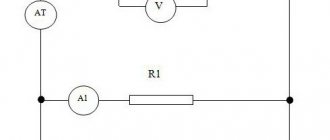
Calculation of power by current
First you need to connect the motor to the network and measure the voltage readings. We measure the current consumption on each of the phase windings using an ammeter or multimeter. Next, we find the sum of the currents of the three phases and multiply them by the previously measured voltage indicators, clearly in the formula for calculating the power of the electric motor by current.
- P – electric motor power;
- U – voltage;
- Ia – 1st phase current;
- Ib – 2 phases;
- Ic – 3 phases.
Variety of devices
The shaft, despite its universal design, can be made in different standard sizes, each of which differs in technological parameters, dimensions, purpose and other characteristics.
Based on the area of use of the electric motor, there are two types of shafts:
- conical Installed on motors controlled by the operation of excavators, cranes, winches;
- cylindrical. They are more common and find their application in equipment components for almost any purpose.
Another popular classification is based on the functionality and purpose of the engine. The shaft element may have one or two ends. In the latter case, the “tails” may all be the same diameter, or the indicator may differ. Often, shafts are mounted in the design of three-phase electric motors for special and general industrial purposes.
It is also quite common to find arrangements in which one end is conical and the other is cylindrical. This option is typical for crane motors, which are characterized by multitasking. Such situations include, for example, lifting and lowering a load, that is, tasks that differ in direction.
The design implies permanent covering of the second end with a cap, therefore, the implementation of a model with two output shafts has an individual character.
In the process of transmitting forces by the shaft, the required rotation speed of the machines performing certain tasks is also set. For this purpose, couplings, pulleys, and keys are also additionally used. This is especially common in mechanisms with a direct motor connection, for example, in automatic washing machines.
Modern designation and decoding of electric motor parameters
The marking has several main positions:
- brand (type) of electric motors;
- execution option;
- working length of the axis of rotation;
- mounting mounting dimensions;
- core length;
- number of pole pairs;
- design modification;
- Climatic performance.
Below is a breakdown of the designations of modern engines.
Below you see an example of complete marking of asynchronous motors and its explanation.
The degree of protection of the electric motor from dust and moisture according to IP class is also indicated, with numbers from 0 to 8. Here the first number is protection from dust, and the second is from moisture.
In this case, the name indicates the installation version. Using the installation code, you can determine how the motors are mounted - on feet or using a flange. For example, IM 1081 talks about foot mounting and that it can be installed with the shaft up, down or horizontally.
For an explosion-proof electric drive, the package of accompanying documents must contain a certificate that indicates the marking according to the degree of explosion protection, its type and scope of application. Also, in the engine marking, if the letter B is indicated at the beginning, it is explosion-proof, for example VA07A(M)-450-710.
In this case, the designation of DC motors differs from alternating current and has the form shown in the figure.
The figure below provides information about traction motors mounted on cranes.
Similar data is placed on the nameplates of electric motors.
The information on the plate says that:
- AIR – type of asynchronous machine;
- 80 – shaft length;
- A-installation size;
- 4-number of poles;
- U - designed for work in moderate climates;
- 3-installed indoors.
Power 1.1 kW, rotation speed 1420 rpm. Can operate on alternating current voltage of 220 or 380 volts when the windings are connected with a delta or star.
The current consumption will accordingly be 4.9/2.8A. Protection degree IP54. Made in the Republic of Belarus.
Shaft terminology
The operation of this stator element is characterized by several terms that are also used when calculating diameters.
Starting torque is a mechanical term that characterizes the rotation that the motor develops on the stator when starting. Occurs when current passes through the unit under full voltage conditions. The shaft itself must be locked.
Minimum torque (M min.) – indicates the lowest point on the torque and motor frequency speed curves. The load of the drive gradually increases to maximum rotation rates.
The locking torque is also known as the overload limit. It is created by an AC type control device, whose rated voltage is supplied at normal frequencies. There are no jumps in the speed of revolutions.
How to find out the power of a wheel motor
To make an approximate calculation of the power of the motor-wheel, you need:
- Measure the current using ammeters connected in series in the circuit. In this case, the ammeter is connected to the open circuit between the battery and the controller.
- Measure the battery voltage. The voltmeter is connected in parallel to the section of the circuit being tested.
- Calculate the product of the measured current and voltage values, i.e. power consumption.
- Multiply the resulting value by the efficiency of the electric motor - we get the amount of power on the MK shaft. The efficiency of the electric motor is indicated by the manufacturer in the documentation and averages 80–90% (when multiplied, the coefficient is 0.8–0.9).
Current and voltage must be measured under load. If you don't have a dynamometer, you should find an alternative. A bicycle computer is suitable for determining speed. Its readings are based on calculations of wheel revolutions and are quite accurate if the correct diameter is specified in the settings.
Then you need to create a load for the electric motor. You can do this in several ways:
- Measure the acceleration time to the maximum speed on a flat and dry section of asphalt road. Using the previous formula (P=IU), calculate the power developed by the electric motor at maximum acceleration.
- Use an electric bicycle or other tested vehicle to overcome a section with a uniform rise. Remember the ammeter and voltmeter values. To calculate the power developed during such a rise, the formula P = IU·efficiency is used (0.8 is taken on average). On climbs of varying steepness, it is possible to approximately calculate the power of a particular electric vehicle that it develops under various conditions. The rated power is considered to be the greatest power developed by the electric motor without harming its serviceability.
- Determine the height of the rise (you can use a GPS navigator) and perform races on it. Calculate the power using the formula P=mgh/t, where m is the total mass of the vehicle and rider in kg, g =9.81, h is the lift height, t is the ride time, P is the power in W.
Determining engine speed using a voice recorder on a smartphone
To do this, you will need a modern smartphone with a voice recorder program installed on it.
In this case, the record must be saved and displayed graphically. For example, the TapeMachine program can do this.
If you don’t have one, you’ll have to record the file in mp3 format, and then open it on your computer in an audio editor. To avoid downloading anything, use popular online services.
Place your smartphone next to the engine and start the engine at idle. Then apply the tip of a screwdriver to the shaft where the key should be.
At this moment, the recorder should capture and record the outgoing sounds of the screwdriver hitting the ribs of the slot for the key. If you have a roller installed on the shaft, then you can wind copper wire onto the end of the shaft, and instead of a screwdriver, take a piece of thick cardboard (sandpaper).
In this case, the shocks will be transmitted from the wire to the cardboard. After running for ten seconds, the engine can be turned off.
Then you begin to analyze the graphic recording. The thin line is the sound of the shaft operating.
Large peaks are the moments of screwdriver impacts. Select the most successful segment from the entire recording and count the number of peaks in 1 second.
Let's say there are 25 of them. This gives 25*60=1500 revolutions per minute.
This is your synchronous shaft speed.
Vladimirus-team
Motor current I = P /(1.73 *U *efficiency* Cosph);
The rated data of the electric motor are indicated on the nameplate or in other technical documentation.
- 1.73 is the root of three;
- U (Volt) - linear voltage;
- P (Watt) - Power of an asynchronous motor
- Efficiency (η) - efficiency factor, taken from the passport data, or in the range 0.8 -0.9;
- Cos(F) - power factor is taken from the passport data, or in the range 0.8 - 0.9.
- I (Ampere) current;
Share on social networks:
Comments
nonsense - the rated current of an electric motor with a power of 55 kW is 1 Ampere.
Hello. You took into account that the power in this calculator must be indicated in Watts.
That is, in the power field we indicate 55000, not 55.
Submit Comment
Mifflin-St. George formula for calculating calories
The Mifflin-St. Geor basal metabolic formula The Mifflin-St.
Calculation of basic metabolism: Mifflin-San Geor formula for a woman: BOO = 10 * weight (kg) + 6.25 * height (cm) – 4.92 * age – 161; Mifflin-San Geor formula for a man: BOO = 10 * weight (kg) + 6.25 * height (cm) – 4.92 * age + 5; By calculating the basal metabolic rate (BMR) using the Mifflin-Saint-Geor formula, you can calculate the approximate number of calories needed per day to maintain body weight, taking into account the level of physical activity.
To do this, multiply the resulting number by the physical activity coefficient.
Physical activity coefficients (K) Minimum load (sedentary work) - K = 1.2 A little daily activity and light exercise 1-3 times a week - K = 1.375 Workouts 4-5 times...
Air conditioner power calculation
The approximate calculation of the cooling power Q (in kilowatts) is made according to the generally accepted method:
Q = Q1 + Q2 + Q3
, where Q1
- heat inflows from windows, walls, floors and ceilings.
Q1 = S * h * q / 1000
, where: S - room area (m2); h—room height (m); q is a coefficient equal to: q = 30 for a shaded room; q = 35 for average illumination; q = 40 for rooms that receive a lot of sunlight. If the room receives direct sunlight, the windows should have light-colored curtains or blinds.
Q2
— the sum of heat inflows from people. Heat gain from an adult: .1 kW
- in a calm state;
0.13 kW
- with light movement;
0.2 kW
- during physical activity;
Q3
is the sum of heat inflows from household appliances.
Heat gain from household appliances: 0.3 kW
- from the computer;
0.2 kW
- from the TV; For other appliances, it can be assumed that they emit 30% of the maximum power consumption as heat (that is, the average power consumption is assumed to be 30% of the maximum...
Heater power calculation
Calculation of heater power Before choosing a heater, you need to calculate the minimum thermal power of your room.
The power depends on: the volume of the room that will need to be heated, the temperature difference between the room and the outside. dissipation coefficient, which directly depends on the insulation of the room and the type of structure. The dispersion coefficient has certain constant values. wooden structures or metal (without thermal insulation) the coefficient is 3-4. with little thermal insulation in a simplified room design 2-2.9. average thermal insulation and standard design coefficient ranging from 1 to 1.9. improved thermal insulation (brick walls, double thermal insulation, thick floor, high-quality roof material), coefficient is 0.6-0.9. To calculate the power of the heater, a simplified system for calculating the required thermal power of the gun, air heater, heater is used: P=V * Δ T * k/860. Heater power calculation onlineRoom height: ...
If you couldn’t find out the power and rpm
If you are unable to find out the power and speed of the electric motors or you are not sure of the measurements, contact the specialists of Quality Systems. Our specialists will help you choose the right motor or repair a broken AIR motor.
The table provides information on the diameter of the electric motor shaft and its dimensions depending on the power and shaft speed.
The connecting dimensions of electric motors are given according to the GOST 2479-79 standard (“according to GOST”). On the domestic market there are electric motors with connection dimensions according to the DIN standard. In our practice, such electric motors are most often found as part of imported equipment.
The connecting dimensions according to GOST and DIN differ slightly. I wrote about these differences here.
And one more thing: the table shows the connection dimensions for a “standard” flange (IM 2081). Some electric motors can be equipped with a flange of reduced size (IM2181, about which our customers call it “small flange”). To clarify the dimensions of the “small” flange connection, please contact us.
Types of electric motors
The most common is the three-phase asynchronous electric motor. DC and synchronous electric motors are rarely used.
Most electrified machines require a drive with a power of 0.1 to 10 kW, a much smaller part requires a drive with a power of several tens of kW. As a rule, squirrel-cage three-phase electric motors are used to drive working machines. Compared to a phase motor, such an electric motor has a simpler design, lower cost, greater operational reliability and ease of maintenance, slightly higher performance indicators (power factor and efficiency), and requires simple equipment for automatic control. The disadvantage of squirrel-cage electric motors is the relatively high starting current. When the power of the transformer substation and the electric motor are commensurate, its start-up is accompanied by a noticeable decrease in the network voltage, which complicates both the start-up of the motor itself and the operation of neighboring pantographs.
Along with three-phase asynchronous squirrel-cage electric motors of the basic design, separate modifications of these motors are also used: with increased slip, multi-speed, with a wound rotor, with a massive rotor, etc. Electric motors with a wound rotor are also used in cases where the power of the supply network is insufficient for starting motor with a squirrel-cage rotor.
The mechanical characteristics of asynchronous electric motors with a squirrel-cage rotor largely depend on the shape and size of the rotor slots, as well as on the method of making the rotor winding. According to these signs
Rice. 1. Torque curves M = f(S) of asynchronous electric motors
There are electric motors with a normal rotor (normal squirrel cage), with a deep groove and with two cages on the rotor. The rotor design of general-purpose squirrel-cage asynchronous electric motors with a power of over 500 W predetermines the phenomenon of current displacement in the winding, which is equivalent to an increase in its active resistance. Therefore, and also due to the saturation of the magnetic paths of dissipation fluxes, such electric motors (primarily the rotor windings) have variable parameters and the analytical expressions of their mechanical characteristics become more complicated. An increase in the active resistance of the rotor during the starting period causes an increase in the initial starting torque with a slight decrease in the strength of the initial starting current (Fig. 1).
Basic requirements for the part
Based on the fact that during the operation of the electric motor it is the shaft that takes on the heaviest load, parameters of increased demands are put forward for it. From the levels of rigidity and strength to the ability to operate smoothly, everything is subject to careful control. Full compliance of parameters directly determines the quality of operation of an individual motor and entire units and production systems.
Based on the nature of the shaft application, manufacturers implement the above-described characteristics at a certain level. For example, the endurance of a motor installed on an excavator should be an order of magnitude higher than that of a shaft for a hydraulic pump motor.
Basic conditions for full compliance with technical requirements:
- smooth transitions in component diameters. Carried out with the aim of maximizing potential stress reduction;
- implementation of key-type grooves for shafts with large diameters. For more reliable fastening of the core;
- production of parts from durable carbon steel (grade 45) or from alloy steel; the key feature of the latter material is the presence of impurities of other metals: nickel, chromium. This is done in order to ensure the highest possible strength and stability to various types of loads;
- carrying out heat treatment of steel blanks to normalize parameters;
- determination of class 2 accuracy for all stages designed for bearings.
Full compliance of the part with all the above-mentioned requirements allows you to buy an electric motor with a long working life, which is suitable for driving various-scale machines and even production lines.
Determining the power of an electric motor without a tag
If there is no technical certificate or tag on the engine, the question arises: how to find out the power of an electric motor without a plate or technical documentation? The most common and fastest methods, which we will discuss in the article:
- According to shaft diameter and length
- By dimensions and mounting dimensions
- By winding resistance
- By no-load current
- By current in the terminal box
- Using an induction meter (for household electric motors)
Determining engine power by shaft diameter and length
The simplest ways to determine the power and brand of an engine are the overall dimensions - shaft or mounting holes. The table shows the lengths and diameters of the shafts (D1) and length (L1) for each model of an asynchronous industrial three-phase motor. Go to detailed overall dimensions of AIR electric motors
When replacing a broken Soviet electric motor with a new one, it often turns out that there is no nameplate on it. We are often asked questions: how to find out the power of an electric motor? How to determine engine speed? In this article we will look at how to determine the parameters of an electric motor without a tag - by shaft diameter, dimensions, current. Order a new electric motor by phone
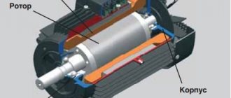
Components of an electric machine
The basis for an electric machine is the rule of electrical induction with magnetic induction. Such a device includes a stator or, as it is called, a constant part (typical for asynchronous, synchronous machines of variable current) or an inductor (for devices of constant current) and a rotor, it is called an active or moving part (for asynchronous and synchronous machines of variable current) or an armature (constant current devices). Magnets (of a constant state) are actively used as a constant part for current machines with low power.
This is interesting: Verification of electricity meters - timing, methodology, cost
Determination by dimensions
Another way is to carry out measurements and calculations. Many of those who are interested in how to find out the power of a three-phase motor prefer it. You will need the following data:
- Core diameter in centimeters (D). It is measured from the inside of the stator. The length of the core is also required, taking into account the ventilation holes.
- Gross rotation frequency (n) and mains frequency (f).
Using them, calculate the polar division index. D multiplied by n and by Pi - let's call this reading A. 120 multiplied by f - this is B. Divide A by B.
As you can see, to calculate the value, it is enough to remember the school mathematics course.
Other features of calculating diameter
Quite often, modern electric motors use hollow type shafts. The coupled loads exert torsion on the component, thereby causing deformation on the surface, including the interior. This allows the use of mechanisms with hollow shafts for vertical engines.
Determining the shaft diameter for such a power unit also requires some effort. The two diameters: internal and external are not standardized categories. This feature does not allow simplifying the calculation procedure by using mathematical relationships.
Another method, also used by some engineers, is to set limits on the amount of twist that can occur when a component is operating. Torsional deflections of loads have values directly proportional to the dimensions of the shaft, that is, the wider the diameter, the higher the resistance index.
The main thing is that the rotated component does not have large dimensions, in order to avoid deviations in length of more than a degree, 15-20 times the diameter.
Why do you need to know engine power?
Of all the technical characteristics of an electric motor (efficiency, rated operating current, speed, etc.), the most significant is power. Knowing the main data, you can:
- Select a thermal relay and automatic circuit breaker with suitable ratings.
- Determine the throughput and cross-section of electrical cables for connecting the unit.
- Operate the engine according to its parameters, avoiding overload.
We described how to measure the power of an electric motor in different ways. Use the one that is optimal in your case. Using any of the methods, you will select a unit that will best meet your requirements. But the most effective option, saving your time and eliminating the need to search for information and carry out measurements and calculations, is to keep the technical passport in a safe place and make sure that the data plate is not lost.
( 1 rating, average 5 out of 5 )