A generally accepted way to ensure safety when working with electrical equipment is grounding. In the PUE, in the list of measures to protect people from the effects of electric current, protective grounding comes first (clause 1.7.51, Chapter 1.7). This measure involves connecting open conductive parts of the electrical installation to a grounding device. Depending on the design features of electrical installations and networks, the grounding loop can be organized in several ways. The system in accordance with which grounding is carried out is determined at the design stage or prescribed by technical conditions issued by the electrical network organization. The subject of this article is the CT grounding system, the operating principle and scope of which will be described in detail below.
Application area
Let's consider in what cases this type of grounding is used. It should be noted that the TT system is in some way an extraordinary measure. The fact is that the PUE prescribes, as a rule, the use of TN grounding in networks with a solidly grounded neutral. It has several varieties, the common design feature of which is the combination of the grounding circuits of the neutral of the transformer and the consumer's electrical installations. Protection carried out according to this principle is most easily feasible from the point of view of the consumer connecting to the electrical network. This system does not require the construction of a grounding device at the consumer's site.
The use of CT earthing is only recommended in cases where the TN system does not provide the required level of safety. This usually occurs when the technical condition of the overhead supply line is unsatisfactory, especially when constructed according to a temporary scheme. Under such conditions, as a rule, there is a high probability of damage to the grounding conductor, that is, loss of electrical connection between the grounding device at the substation and the grounding circuits of the consumer. This situation is fraught with the fact that in the event of an insulation breakdown, the touch voltage on electrical equipment casings may be equal to the operating voltage of the network. For this reason, the main area of application of the TT circuit is objects whose power supply is temporary. For example, construction sites, trailers, etc.
Quite often there are cases when CT grounding is used in a private house or country house. The implementation of such a scheme is quite labor-intensive, especially for a private owner. Questions about how to make a grounding switch and install an RCD can probably only be resolved by specialists. Not every owner can build a grounding device on his property that meets the requirements of the rules. To the above, we can also add that the use of the system should be agreed upon with the organization providing electricity.
In accordance with the PUE, the operation of electrical equipment grounded according to the TT system is prohibited without the use of an RCD. Figure 2 illustrates the RCD connection diagram.
A residual current device (RCD) is a protection system that shuts down the installation when a leakage current occurs due to insulation damage. This device reacts to the difference in currents flowing through the phase and neutral wires, therefore it is called a differential current circuit breaker. If the insulation of an electrical installation is damaged, a shunt circuit is formed through the equipment housing to the ground. As a result, a leakage current to grounding is generated.
General description and principle of operation
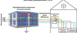
The use of the TT system extends to electrical networks whose neutral is solidly grounded. The essence of this method is that the conductive parts of electrical equipment are connected to a grounding device located on the consumer side. There is no electrical connection between this device and the ground electrode to which the neutral of the transformer at the substation is connected.
The figure schematically shows the TT system through which the building is grounded:
Types of artificial grounding
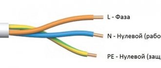
If we consider the functionality, then there is a protective and working grounding. The first ensures the safety of people when using electrical appliances, and the second ensures the normal operation of electrical installations. Based on the type of grounding, the neutral wire is divided into systems with insulated (IT) and solidly grounded (TN) neutrals. The figure shows all types of grounding.
In an IT system, the neutral wire of the electricity generator has no galvanic connection to ground, and conductive parts are intentionally grounded. It is allowed to install an arc-forming device or devices with high internal resistance between the ground electrode and the neutral.
The TN grounding system is the most common. In it, the neutral wire of the electricity generator is solidly grounded, and the conductive parts are connected to it using special buses.
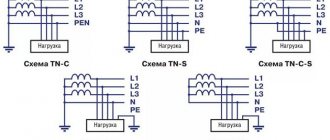
It is further divided into four subspecies:
- TN-C grounding system, in which the working and protective neutral wires represent one conductor from the source to the energy consumer;
- TN-S system, in which the working and protective neutral wires are two conductors from the source to the energy consumer;
- TN CS grounding system, in which the working and protective neutral conductors are one conductor, starting from the electricity generator, then at some point they are divided into two;
- TT system, in which the neutral wire of the electricity generator is solidly grounded, and the open conductive parts of the electricity consumer are grounded through their own grounding, which is in no way connected with the neutral wire of the electricity generator.
The first character of the abbreviation indicates the state of the neutral wire of the electricity generator (generator, transformer) relative to the ground layer.
T – grounded neutral conductor.
I - insulated neutral conductor.
The second symbol informs about the state of conductive parts regarding grounding.
T - conductive parts are grounded, the state of the neutral wire of the electricity generator does not matter;
N - conductive parts are connected to the solidly grounded neutral conductor of the power supply.
The symbol after N shows how the working and protective neutral conductors relate.
S (separated)—the working (N) and protective (PE) neutral conductors are separated. C (combined) - N and PE conductors are combined into (PEN) wire.
Housing installation
When installing outside the home, it is recommended to use steel electrical panels (No. 1 in the image), which can be locked. The degree of protection from dust or moisture must be at least IP54.
Typically, the shield is mounted at the boundary of the site, for example, on a power line support, a building wall or a fence. Depending on the ease of access to it for inspectors. It is best to bring wires and cables inside for switching, preferably from below, using sealed leads. This way you will ensure maximum tightness and significantly protect the electrical installation as a whole.
All modern switchboard equipment is mounted on DIN rails. Make sure that the shield you purchase has them installed or included. Otherwise, you will have to buy an additional DIN rail.
IT system
The IT system is intended for use in institutions where highly sensitive instruments can be used (laboratories, medical facilities).
The peculiarity of IT comes down to the fact that the neutral of the transformer substation is insulated in relation to the ground, or special instruments and devices with high resistance are used for grounding.
But open areas of electrical installations are grounded in the classical way - through a grounding loop.
The use of an IT system ensures minimal exposure to electromagnetic fields on sensitive equipment.
IMPORTANT TO KNOW: How to ground a washing machine
Wires from the input machine to the meter
The next step is to lay the wires from the lower terminals of the input machine - 3 phases and connect them to the corresponding contacts of the electric energy meter.
We discussed in detail how to connect a three-phase electricity meter, in what order to connect the wires HERE, using the Energomer CE 306 device as an example.
TT grounding system.
TT system is a system in which the neutral of the power source is solidly grounded, and the exposed conductive parts of the electrical installation are grounded using a grounding device that is electrically independent of the solidly grounded neutral of the source.
1 - power supply grounding switch; 2 - open conductive parts;
3 - equipment housing grounding switch
Power supply of electrical installations with voltage up to 1 kV from a source with a solidly grounded neutral and with grounding of exposed conductive parts using a ground electrode not connected to the neutral (TT system) is allowed only in cases where electrical safety conditions in the TN system cannot be ensured. To protect against indirect contact in such electrical installations, the power must be automatically turned off with the mandatory use of an RCD. In this case, the following condition must be met:
where Ia is the tripping current of the protective device; Ra is the total resistance of the grounding conductor and the grounding conductor, when using an RCD to protect several electrical receivers - the grounding conductor of the most distant electrical receiver. (PUE1.7.59.) In the TT system, the transformer substation has a direct connection of current-carrying parts to the ground. All exposed conductive parts of the electrical installation, in the CT grounding system. directly connected to the ground through a ground electrode electrically independent from the neutral of the transformer substation. The neutral conductor of an overhead line or cable line, in electrical installations with a TT grounding system, performs the functions of only the neutral working conductor (N).
The TT grounding system was allowed relatively recently in PUE-7, and in the edition of PUE-6 the TT system was prohibited:
The TT system was approved when mass use of ouzo became possible. Why is it prohibited without an RCD?: In a system with a grounding conductor electrically independent from the neutral of the transformer substation (TT system), in the event of a short circuit to ground, the probability that the circuit breaker will trip is very small (this requires a very low resistance of the grounding conductor, ensuring a high multiplicity short circuit current, etc.). The circuit breaker in the TT system will only operate if there is a short circuit between the working zero and the phase.
Installation of a box for an input circuit breaker
In order to prevent unauthorized connection, bypassing the electric meter, all switching and protective devices located before it must be closed in boxes (No. 2 in the image) and sealed.
So, during installation, we first install a special housing for the AB (circuit breaker). It differs in that it has “ears” for easy filling. In a three-phase 380V network, the box is installed on at least three modules so that the Circuit Breaker fits there.
How to make a ground loop
In apartment buildings, the transition to the TN-CS grounding system is usually carried out by specialized enterprises. They make the appropriate switches in the ASU of the house or entrance and install an additional grounding loop. Practice shows that there are cases when residents who are illiterate in electrical engineering, but not overly active, try to modernize the power supply circuit for their individual apartment on their own. For this purpose, they try to use water supply or heating risers as a grounding loop, which is strictly prohibited, because This method inevitably leads to electrical injuries and has a detrimental effect on the service life of pipelines and heating devices.
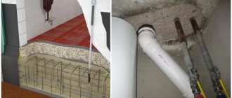
For the conditions of a private home, it is not difficult to make additional grounding; the most popular and reliable is a closed circuit in the form of a triangle:
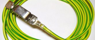
The electrode immersed in the ground is angle steel, the jumper is a steel strip, the grounding conductor is a steel rod. The cross-sectional area of the steel components of the circuit must be at least 50 mm2. We talked in more detail about how to make grounding in the house in a separate article!
Installation of the machine
The input machine (No. 3 in the image) is installed in a separate housing, which is closed with a casing. Later, representatives of the energy sales company will seal it, install a seal and check it every time readings are taken or control rounds are taken.
For three-phase 380V networks, with an allocated power of 15 kW, the rating of the circuit breaker should be 25A.
Requirements for the grounding device
The most important characteristic of a grounding device is its resistance. The requirement for this parameter, if grounding is performed according to the TT system, can be expressed as follows:. In this case, in the case of using several residual current devices, the differential operating current of the device where it has the maximum value is taken into account
In this case, in the case of using several residual current devices, the differential operating current of the device where it has the maximum value is taken into account.
In addition to this requirement, the basic system of potential equations must be met. The essence of the event is to connect the following structures together:
- Grounding device made on site.
- Metal pipelines for heating, water supply (cold and hot), sewerage, gas supply.
- Metal structures related to the building frame.
- Metal parts of ventilation systems and air conditioning systems.
- A grounding device included in the lightning protection of a private home.
TN-C grounding system
TN grounding refers to systems with a solidly grounded neutral. One of its varieties is the TN-C grounding system. It combines functional and protective neutral conductors. The classic version is represented by a traditional four-wire circuit, in which there are three phase and one neutral wire. A solidly grounded neutral is used as the main grounding bus, connected to all conductive open parts and metal parts using additional neutral wires.
The main disadvantage of the TN-C system is the loss of protective qualities when the neutral conductor burns out or breaks. This leads to the appearance of life-threatening voltage on all surfaces of device housings and equipment where insulation is missing. In the TN-C system there is no protective grounding conductor PE, so all connected sockets are also not grounded. In this regard, all electrical equipment used requires a grounding device - connecting the housing parts to the neutral wire.
If the phase wire touches the open parts of the housing, a short circuit will occur and the automatic fuse will trip. Quick emergency shutdown eliminates the risk of fire or electric shock. It is strictly prohibited to use additional potential equalization circuits in bathrooms if the TN-C grounding system is used.
Despite the fact that the tn-c scheme is the simplest and most economical, it is not used in new buildings. This system has been preserved in old residential buildings and in street lighting, where the likelihood of electric shock is extremely low.
Planned assignments of grounding systems
To fully understand the purpose of various systems, a detailed analysis of each of them, including subsystems, is necessary. The most important points are the operating principle and, accordingly, the basic focus.
TN system
In this system, the neutral of the power source is solidly grounded, and external conductive parts of the electrical wiring are connected to it using a neutral protective conductor. The term “solidly grounded neutral” means connecting conductor N directly to the ground loop (mounted near the transformer substation), and not to the arc suppression reactor.
TN-C subsystem
In TN-C, the neutral working and protective conductors are combined into a single conductor throughout the entire system. The prefix “C” is taken from the word “combined”, which means “united”. The advantages of the system include its simplicity and cost-effectiveness. For this reason it is very common.
The key disadvantage of TN-C is that there is no separate protective earth (PE) conductor. In practice, this is equivalent to the lack of grounding in the sockets of a residential building. Often in such systems, zeroing is done. This measure is extreme and is designed for the short circuit principle. If a phase conductor gets on the device body, the circuit breaker will trip following a short circuit. It is not possible to equalize potentials in the bathroom using TN-C. This subsystem was actively used in old residential buildings. It is not recommended for modern housing.
Subsystem TN-S
In TN-S, the neutral conductors function separately throughout the entire system. The prefix “S” is taken from the word “separated”, which means “separate”.
This grounding subsystem is the most advanced and safe. When constructing new buildings, its use is recommended. It provides good protection for people, equipment and structures.
However, despite the above advantages, TN-S is not very common today. This is due to the fact that to create it it is necessary to use a five-core cable (three-phase network) or a three-core wire (single-phase network). The result is an increase in the cost of the project.
Subsystem TN-CS
In this case, the neutral conductors are combined into a single one at some segment of the system. In the interval from the power supply to the system entering the building, splitting into N and PE conductors can be carried out. In this case, re-grounding will be necessary.
The advantages of the subsystem include its easy implementation from a technical point of view. When switching from TN-C, a fairly simple upgrade is required. TN-CS is recommended for widespread use.
The disadvantage of TN-C lies in the need to modify the access risers. Another unpleasant moment: a break in the PEN conductor can create a dangerous potential for electrical appliances.
TT system
In the TT system, the source neutral is solidly grounded. As for the external conductive parts, they are connected to another ground electrode, which is electrically independent from the first one.
Until relatively recently, this grounding system was prohibited. Today it is permitted and quite in demand. TT is often used for movable buildings, for example, trailers, stalls, pavilions, etc. Its use is permissible only in situations where the necessary electrical safety conditions cannot be achieved in the TN system.
Such a system necessarily requires high-quality re-grounding, characterized by impressive resistance values. Modular pin type grounding is the most effective and practical solution in such conditions. Also, for all of the above systems, the use of a residual current device is highly recommended. The presence of an RCD has a positive effect on safety.
IT system
This system is characterized by isolation of the neutral from the ground or grounding through devices/devices with the highest resistance. The external conductive elements of the installation are grounded.
All kinds of scientific/medical institutions and laboratories are grounded through the IT system. This is justified by the fact that in such institutions there is highly sensitive equipment, and experiments are often carried out. Therefore, it is necessary to minimize all currents and fundamental physical fields.
Grounding schemes for a private house TN-CS and TT
Grounding schemes for a private house TN-CS
When powering a house according to the TN-CS scheme, the role of a protective conductor and a neutral working conductor in the network section from the current transformer to the main grounding bus is played by one wire (PEN). On the main ground bus (GZB) PEN, the conductor is divided into a neutral working conductor (N) and a protective conductor (PE).
1-source grounding; 2-house.
It is important to remember that the PEN conductor comes from the transformer substation, where it is connected to the neutral wire of the windings and connected to ground without resistance. This neutral is called solidly grounded
Thus, when grounding a house according to the TN-CS scheme, the main ground bus (GSB) of the house is connected to the ground of the supply transformer. And, at first glance, it seems that such a connection is enough to ground all sockets and electrical equipment in the house. But it is not so. It all depends on where the main grounding bus (GGB) of the house will be located.
Option 1. Power supply to the house is carried out through an input device (ID) on a power line pole (PTL).
In this case, the main grounding bus (GZSh) is located on the pole and the division of the PEN conductor into the working neutral wire (N) and the ground wire (PE) occurs on the pole in the switchboard.
Option 2. Power supply to the house is carried out through an input distribution device (IDU) located in or near the house.
In this case, the division of the PEN conductor into a working neutral wire (N) and a grounding wire (PE) occurs directly in the house, and from the pole to the house the roles of the protective conductor and the neutral working conductor are combined. With this option for connecting the power supply, it is necessary to re-ground the house.
In both options, the grounding of a private house using the TN-CS system is connected to the grounding of the power source (transformer). This connection between the power supply ground and the house grounding system does not exist in a TT grounding system.
Grounding schemes for a private house TT
1-source grounding; 2-house; 3-house grounding.
Grounding schemes for a private house according to the TT scheme exist, but again with small “buts”.
In order to make grounding using the TT system, you need to provide a justification for refusing the TN-CS system and fulfill all the requirements established for the TT system. So what is the peculiarity of the TT system for grounding a private house.
Features of the TT grounding system
- The house grounding system is independent of the neutral of the power source (transformer);
- The grounding conductor of equipment housings in the house does not depend on the grounding of the power source (transformer);
- In electrical wiring made according to the TT scheme, the use of residual current devices (RCDs) is mandatory. Without an RCD in the TT circuit, the system for protecting a person from any current leakage in the event of insulation damage is completely absent. And this is unacceptable.
Due to the complexity of the practical implementation of grounding a private house using the TT scheme, the vast majority of private houses are grounded using the TN-CS system.
I repeat: The grounding system for a private house according to the TN-CS scheme involves combining the protective conductor (PE) and the neutral working conductor in separate sections of the electrical wiring before distributing the power supply.
Elesant.ru
Normative references:
- PUE, Electrical Installation Rules, edition 7
- GOST 121.030-81, Electrical safety. Protective grounding. Zeroing
- 26 Rules for power supply and wiring of a wooden house. part 1, rules 1-7
- 26 Rules for power supply and wiring of a wooden house. part 2, rules 8-13
- 26 Rules for power supply and wiring of a wooden house. part 3, rules 14-26
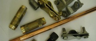
- Anchor clamps and brackets
- Fittings for SIP 2
- Inserting cables from the trench into the house
- Input device. VU for a private house
- VRU. House input and distribution device
- GZSH. Main Grounding Bus
- Deep ground electrode
Tags: automatic, sconce, vago, view, switch, generator, house, , clamp, grounding, ground, protective, insulation, cable, like, circuit, crown, , magnet, voltage, neutral, connection, potential, rule, principle, wire, project, start, , work, socket, row, network, system, connection, resistance, means, term, diagram, ten, type, current, transformer, triangle, , installation, shield, power supply