Topic No. 28 Technology for testing DSS relays
7 Checking and repairing the contact system
Check the strength of the riveting and the quality of soldering of the contact and thrust springs to the output knives. The fastening must be rigid, soldering with a flat surface.
The carbon contacts of the relay must not have cracks, chips, and must not move in metal holders. The distance between the contact surface of the carbon contacts and the lower edges of the metal holders must be at least 1.5 mm. Check the reliability of fastening of the contact groups by grasping each contact group with tweezers and attempting to move it relative to the base of the relay.
Grind the carbon and silver contacts. Eliminate fraying or burnt contacts using a needle file and sandpaper. If the amount of wear on the silver contact exceeds 0.2 mm, replace the contact with a new one. When the rods are removed, the movable contact springs must be in contact with the disconnecting contacts. If necessary, bend the movable springs at the base.
8 Installation of a sector with an axis and contact rods
Insert the sector into the air gap between the poles of the cores. Secure the sector axis in the axial screws, preventing it from distorting when installed in the bearings of the axial screws. By moving the axial screws, set the sector in the center of the gap of the magnetic system. Secure the axial screws with locknuts and measure the air gaps between the sector surface and the poles of the magnetic system. They should be 0.35mm at any position of the sector. During this measurement, the sector must be moved towards the gap being measured by the amount of the longitudinal play of its axis. Check the longitudinal and transverse play of the sector. They must correspond to the data in Table 2.
The longitudinal play is regulated by rotating the axial screws, the transverse play by selecting them according to their diameter.
table 2
| No. | Parameter name | Limit value |
| The size of the gap between the poles of the magnetic system, not less than, mm | 2,0 | |
| The gap between the surfaces of the sector and the poles of the cores of magnetic circuits, not less than, mm | 0,35 | |
| Distance between any parts of the buffer crimps of the sector and the cores of the magnetic circuit, not less, mm - in the lower position of the sector - in the upper position of the sector | 1,5 3,0 | |
| Longitudinal play of the sector axis, mm | 0,15-0,25 | |
| Transverse play of the sector axis, mm | 0,02-0,06 | |
| Distance between contacts at extreme positions of the sector, not less, mm | 1,5 | |
| The solution between the contacts when switching them (the solution between the movable and the closing contact at the moment of separation of the movable from the breaking contact, not less than, mm | 0,8 | |
| Pressure on the closing contact, Gs | 20±3 | |
| Pressure on the breaking contact, not less, Gs | 20,0 | |
| Contact slippage (the distance covered by the movable and stationary contact springs when the relay is activated or released), not less than, mm | 0,25 | |
| Non-simultaneous closing and opening of contacts, no more, mm | 0,4 |
Check the rotation of the sector: the sector axis should rotate freely in the bushings without jamming, and the ends of the trunnions when moving along the axis should rest against the ends of the thrust bearings.
When the buffer crimp touches a roller sector that is pressed all the way, the distance between any parts of the second buffer crimp and the cores must be at least 1.5 mm when the sector is in the lower position and at least 3.0 mm when the sector is in the upper position.
Attach the contact rods to the movable contacts, rotating the sector, check their freedom of movement. The contact rods should not have any engagement in the hinges.
Tighten the locknuts of the axle screws completely. The position of the locknuts of the sector axial screws and counterweights after adjustment must be fixed with paint.
Place the front plate with roller holders on the frame, securely screw it to the frame with screws and washers.
9 Adjusting the contact system
Check the size of the gaps with feeler gauges and make adjustments by bending the thrust plates.
Adjust the solution between the moving and fixed contacts when the sector is in the extreme positions and the crimps touch the rollers. The gaps must be at least 1.5 mm.
Adjust the solution between:
-moving and closing contacts at the moment of separation of the moving contact from the breaking contact;
-moving and breaking contacts at the moment of separation of the moving contact from the closing one;
The moment of separation is considered to be the moment the light indicator that controls the closed state of these contacts is turned off. The gaps must be at least 0.8 mm.
Adjust the joint travel (slippage) of the contacts:
- set the sector to the position at which the moving and breaking contacts touch (close), determine the gaps between the thrust and contact springs at the breaking contacts;
- set the sector to the position in which the moving and closing contacts touch (close), determine the gaps between the thrust and contact springs at the closing contacts.
The relay contacts must be in contact on adjacent surfaces and provide a joint stroke (slippage) of at least 0.25 mm when the contacts close.
Using a grammeter, check the pressure of the moving contacts on the stationary ones; its value should be 20±3G for each make contact and at least 20G for each break contact. Adjust the pressure by bending the thrust plates.
Adjust the simultaneity of closing and opening the contacts. The permissible non-simultaneous opening (closing) of contacts is no more than 0.4 mm.
10 Checking electrical and timing parameters
The main electrical and timing parameters of the DSS relay are given in Table 3.
Table 3
| Parameter | Relay type | |||||||
| DSSH12 | DSSH13 | DSSH13A | DSSH15 | DSSH16 | ||||
| Supply voltage frequency, Hz | ||||||||
| Local element (LE) | ||||||||
| Rated voltage, V | ||||||||
| Current, no more than, mA | ‑ | ‑ | ||||||
| Track element (PE) | ||||||||
| Lifting voltage, no more than, V | 14,0 | 15,5 | 15,5 | 12,0 | 12,5 | 12,5 | 14,8 | 14,8 |
| Rise current, no more, mA, | 26,0 | 26,0 | 26,0 | 38,0 | ‑ | ‑ | ‑ | |
| Release voltage, V | 8-9 | 9-10 | 9-10 | 7-7,5 | Not less than 9.0 | Not less than 9.0 | 9-10 | 9-10 |
| Response time, no more, ms | ‑ | ‑ | ‑ | ‑ | ||||
| Nominal phase shift angle, degrees | ||||||||
| The track element current lags behind the local element voltage | ||||||||
| The voltage of the track element lags behind the voltage of the local element | 87,5 | |||||||
| Deviation of phase shift angle from nominal, degrees, no more | ||||||||
| Between current and voltage | 5,0 | |||||||
| Between voltages | 2,5 |
It should be taken into account that during operation of the relay, the coils heat up and the value of the actuation (release) voltage changes.
The standards for the electrical parameters of the relay when the ambient temperature changes are given in Table 4. If the electrical parameters of the relay correspond to the data in Table 4, write down the characteristics corresponding to a temperature of 20° in the test log.
The electrical parameters of the relay are measured at one frequency (either 50 or 25) Hz depending on the type of relay.
If the electrical parameters of the relay are measured at a frequency of 25 Hz, the phase shift angle should be set between the voltages on the local and track elements. When measuring electrical parameters at a frequency of 50 Hz, it is allowed to set the phase shift angle between the voltage at the local element and the current of the track element. The nominal phase angle is indicated in Table 3.
Measure the parameters as follows: set the rated voltage on the local element (Table 3). Set the lifting voltage on the track element, set the nominal phase angle (Table 3). Reduce the voltage on the track element to zero. Smoothly increasing the voltage on the track element, fix it at the moment of contact of the sector with the upper thrust roller, maintaining the voltage value on the local element and the phase shift angle. This will be the lifting voltage. Smoothly reduce the voltage on the track element until the front contacts open. This will be the release voltage. If the measured parameters do not correspond to the data in Table 3, make adjustments.
The drop-out voltage can be adjusted using a counterweight. If the adjusting stock of nuts is not enough, make it easier by replacing them with thinner ones (6 mm for DSSh12, DSSh13, DSSh13A) or by drilling three holes in the lock nut with a diameter of (2.5-3.0) mm. Drill holes between the center and the edge of the nut at an angle of 120°, and cover their surface with varnish or paint.
The lifting voltage should be adjusted by contact pressing within the permissible range (17-23) Gs.
If the lifting standard cannot be obtained, the lifting tension should be eliminated by shifting the counterweight nuts and the lifting voltage should be measured again.
In relays with a unified sector bushing design, adjust the electrical parameters of the DSSh15, DSSh16 relays by rotating the adjusting screw Mx6 (Fig. 3, item 1). After obtaining the required parameters, secure the screw with nuts (Fig. 3, item 2), which must be tightly tightened.
Apply a control mark to the screw, nuts and sector bushing (Fig. 3).
In the DSSh12 and DSSh13A relays, the screw (Fig. 4, item 1) must be screwed into the bushing (Fig. 4, item 3) until it stops and locked with a nut (Fig. 4, item 2). Adjust the electrical parameters by moving the other two nuts (Fig. 4, item 4). After obtaining the required parameters, lock the nuts relative to each other, and also apply a control mark (see Fig. 4).
Set the local element to the rated voltage. Measure the current value and compare it with the data in Table 3. Increase the voltage on the track element to the rise voltage and measure the current on the track element. Compare with the data in Table 3.
Response time measurement
Measure the relay response time as follows: set the rated voltage with a frequency of 50 Hz on the local element, and set the rise voltage on the track element at the rated phase angle. Remove the voltage from the relay track element winding, connect a relay timing meter and measure the time from the moment voltage is applied to the relay track element until the closing contacts are closed. The relay response time should be no more than 245ms. The relay response time is adjusted by pressing the normally open contacts. As the pressure increases, the response time decreases.
If there is no standard parameter (‑) in Table 3, do not take the measurement.
Contact resistance measurement
Check the contact resistance of the contacts using a voltmeter-ammeter method using direct or alternating current. In this case, the current through the closed contacts should be (0.5 + 0.005) A. It is allowed to use an immittance meter to measure the contact resistance of contacts.
If the resistance of the contact circuit exceeds the established norm (0.5 Ohm without socket contacts), clean the contacts and repeat the measurements.
Table 4
| Parameter | DSSH12 | DSSH13 | DSSH13A | DSSH15 | DSSH16 | |
| Supply frequency | 50/25 | 50/25 | ||||
| Lifting voltage, V, at air temperature, °C | 13,65 | 15,11 | 15,11 | 11,70 | 12,28 | 14,54 |
| 13,72 | 15,19 | 15,19 | 11,76 | 12,33 | 14,59 | |
| 14,00 | 15,50 | 15,50 | 12,00 | 12,5 | 14,8 | |
| 14,28 | 15,81 | 15,81 | 12,24 | 12,7 | 15,04 | |
| 14,42 | 15,97 | 15,97 | 12,32 | 12,8 | 15,16 | |
| 14,56 | 16,12 | 16,12 | 12,48 | 12,9 | 15,27 | |
| 14,70 | 16,14 | 16,14 | 12,60 | 13,0 | 15,39 | |
| Release voltage, V, at temperature, °C | 7,800-8,775 | 8,775-9,750 | 8,775-9,750 | 6,830-7,556 | no less than 8,874 | 8,874-9,825 |
| 7,840-8,820 | 8,820-9,800 | 8,820-9,800 | 6,860-7,595 | no less than 8,899 | 8,899-9,888 | |
| 8,000-9,000 | 9,000-10,000 | 9,000-10,000 | 7,000-7,750 | not less than 9,000 | 9,000-10,000 | |
| 8,160-9,180 | 9,180-10,200 | 9,180-10,200 | 7,140-7,905 | not less than 9.126 | 9,126-10,140 | |
| 8,240-9,270 | 9,270-10,300 | 9,270-10,300 | 7,210-7,983 | not less than 9,189 | 9,189-10,210 | |
| 8,320-9,360 | 9,360-10,400 | 9,360-10,400 | 7,280-8,060 | not less than 9.259 | 9,259-10,280 | |
| 8,400-9,450 | 9,450-10,500 | 9,450-10,500 | 7,350-8,138 | not less than 9.315 | 9,315-10,350 |
11 Checking the operation of the DSS relay in the resonant rail circuit
The check is carried out when the DSS relay operates in resonant track circuits.
Place the relay in a plug socket located horizontally; set the rated voltage on the ME relay according to Table 3; connect a capacitor with a capacity of 5 μF to the PE winding; at the moment the capacitor is connected, the relay sector must be stationary or move in the direction of the breaking contacts; measure the voltage on the PE.
Relays in which the sector is stationary when connected to the capacitor PE or moves in the direction of the breaking contacts, and the voltage on the PE does not exceed 5V, are considered suitable for operation in a resonant track circuit.
Relays in which the sector moves in the direction of the NO contacts when a capacitor with a capacity of 5 μF is connected, as well as relays in which the sector moves in the direction of the NC contacts, but the voltage on the PE exceeds 5V, cannot operate stably in resonant rail circuits and require adjustment of the magnetic system .
Adjust the magnetic system with the sector removed.
Place a 2.0-2.5 mm probe between the poles of the magnetic system in accordance with the actual relay gap; loosen the screws securing the ME magnetic system; move the magnetic system of the ME relative to the PE within the backlash of the fastening screws, keeping the existing gap between the poles unchanged using a feeler gauge. For relays whose sector moves in the direction of the NO contacts, move the ME magnetic system in the direction of the NC contacts, and for relays whose sector moves in the direction of the NC contacts and the voltage on the PE with a 5 µF capacitor is greater than 5V, move the ME magnetic system in the direction of the NO contacts, tighten the screws securing the ME magnetic system, and then remove the probe.
If by moving the magnetic system of the ME it is not possible to ensure the conditions for stable operation of the relay in the resonant track circuit, it is possible to similarly move the magnetic system of the PE relay in the direction opposite to the direction of movement of the magnetic system of the ME.
12 Filling out the label
Secure the mounting screws with enamel. Fill out the label, put it inside the casing, blow out the relay with compressed air and hand it over to the receiving electrician for control.
13 Control check
The electrician-inspector checks the correct assembly of the relay, the fastening of all parts, the quality of soldering, and the compliance of mechanical and electrical parameters with established standards.
Check the electrical parameters with the casing on the relay. If the relay parameters comply with the established standards, write them down in the test log (draw up a test report when using automated control systems).
14 Relay closing
Blow out the relay with compressed air, stick a label on the casing, put on the casing, fasten the screws securing it, while ensuring a visible gap between all live parts and the relay casing (at least 3mm).
15 Insulation resistance measurement
Measure the insulation resistance with a megohmmeter at a DC voltage of 500V. Between electrically unconnected current-carrying parts of the relay, as well as between them and the “body” it must be:
a) under normal climatic conditions, not less than 200 MOhm;
b) under conditions of exposure to high humidity (95+3)% at a temperature of (20+5)°C not less than 50 MOhm, and for windings not less than 2 MOhm.
16 Relay marking
The electrician-receiver fills the places where the stamp is applied with mastic and puts a personal stamp stamp
⇐ Previous7Next ⇒
Recommended pages:
Application
Solid state relays are used to control electronic devices, equipment and automatic systems connected to an electrical network with a power of 20 to 480 watts.
Used in various fields:
- automation of industrial processes;
- various household installations;
- heat regulation systems in heating elements;
- in lighting control systems and motion sensors;
- car electronics.
The relay is found in refrigerators, kettles, washing machines, heating elements, and uninterruptible power supplies.
The areas of use of solid-state devices depend on their design, connection diagrams and other operating conditions.
TSRs do not require constant maintenance and can be installed in any hard-to-reach places.
The popularity of solid-state devices is increasing every day, thanks to widespread automation.
Advantages and disadvantages
The advantages of solid-state models include:
- absence of noise and vibration;
- compact dimensions;
- wide scope of application;
- instantaneous switching speed (thousandths of milliseconds);
- no electromagnetic interference when turned on;
- long service life due to the absence of moving parts;
- constant output resistance throughout the entire service life;
- minimal electrical energy consumption;
- possibility of load regulation;
- low sensitivity to vibrations, high humidity, dust, and magnetic fields.
The switching life of solid-state relays is a thousand or more times higher than that of electromagnetic analogues.
When operating such devices, the possibility of sparks occurring during switching is eliminated, which allows the devices to be used in explosion- and fire-hazardous facilities.
The main disadvantages of solid-state relays:
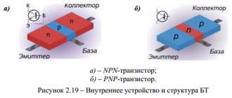
- heating of the device due to high resistance in the pn junction circuit;
- frequent false alarms during power surges;
- the possibility of failure of the power switch due to overloads and short circuits;
- high price.
The SSR has a leakage current, due to which the phase wire may be energized even when the relay is turned off.
Devices designed to operate in direct current conditions require strict adherence to polarity when connecting output circuits.
Solid state relays are periodically checked for package integrity and insulation.
