Checking, adjusting and setting up thermal relays type TRN, TRP
Very often one comes across electrothermal relays of the TRN and TRP types as maximum current protection in electrical facilities. I have already written in detail about these relays earlier. However, in these relays it is necessary to periodically configure and adjust the response settings. This is exactly what we will talk about today.
Before checking and adjusting thermal relays, you must:
– inspect thermal relays;
– create the necessary temperature conditions (not lower than +20 o C) in the room where they are installed. If it is impossible to create normal temperature conditions in the room where thermal relays are installed, testing of these relays must be carried out in laboratory conditions.
Carry out an external inspection of the thermal relays. During inspection, check:
1) reliability of tightening contacts and connecting thermal elements;
2) good condition of heating elements, condition of bimetallic plates;
3) clarity of operation of the mechanism associated with the relay contacts and the contacts themselves, absence of jamming or delays;
4) cleanliness of contacts and bimetallic plates, relay cooling conditions;
5) the absence of rheostats and heating devices near the relays, the possibility of blowing from fans.
When adjusting, it is necessary to take into account that the thermal elements at the manufacturer’s factory are calibrated at a temperature of 20 o ± 5 o C for thermal relays of the TRN series and at a temperature of 40 o C for thermal relays of the TRP series, therefore, when testing the relay, it is necessary to adjust the rated current supplied to the relay, taking into account ambient temperature.
TRN series relays are bipolar with temperature compensation, available for currents of 0.32 - 40 A with a set current regulator; for relays of type TRN-10a in the range from –20 to +25%, for relays TRN-10, TRN-25 – in the range from –25 to +30%.
The relays have only manual reset, carried out by pressing a button after 1 - 2 minutes. after the relay is activated. Thanks to temperature compensation, the set current is practically independent of air temperature and can vary within +3% for every 10 o C change in ambient temperature from +20 o C.
TRP series relays are single-phase, without temperature compensation, produced for a current of 1-600 A, with a set current regulator. The mechanism has a scale with five divisions on both sides of zero.
The division price is 5% for open execution and 5.5% for protected execution. At an ambient temperature of +30 o C, a correction is made within the relay scale: one scale division corresponds to a temperature change of 10 o C. At negative temperatures, the stability of the protection is disrupted.
Design
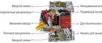
The modern electrical equipment market offers a huge selection of thermal relays of different operating principles; as a result, their design will also differ. However, in accordance with clause 3.2. GOST 16308-84 all technical parameters of a particular model must correspond to this type in terms of dimensions, design and circuit diagram of this type. The most common option, due to its ease of implementation and relative cheapness, is an electrothermal relay on a bimetallic plate. The design of which is shown in Figure 1.
Rice. 1. Thermal relay design
As you can see, the mechanism includes:
- heating element - a current-carrying part that passes through itself the operating current of an electric machine;
- bimetallic plate - acts as an active indicator that reacts to excess temperature;
- pusher - performs the functions of a rigid lever that transmits force from a bimetallic plate;
- temperature compensator – allows you to make a correction for the ambient temperature to stabilize the operating current value;
- latch – designed to fix the position of the temperature relay;
- release rod - a moving part of the mechanism designed to move contacts;
- relay contacts – transmit power to the control unit;
- spring - creates a force to move the relay to a stable position.
In practice, there are other types of relays, the design of which will be fundamentally different. This option is given as an example to illustrate the processes and explain the operating principle.
Thermal relay: connection diagram, operating principle, purpose
Thermal relays are electrical devices whose main purpose is to protect the motor from excess load and, as a consequence, overload of the system as a whole. Today, the most common types of thermal relays are: TRN, RTI, RTT and RTL. The need to use thermal relays is due to the fact that the durability of any equipment directly depends on how often it is overloaded. Thus, when the rated voltage is regularly exceeded, the equipment heats up, which leads to aging of the insulation and, as a result, reduces the operating life of the installations.
Continuity testing of air conditioning compressors
The most common type of compressor in air conditioners is single-phase compressors with a starting winding.
To gain access to the compressor contacts, it is necessary to disassemble the air conditioner so that there is access to the compressor. Usually the contacts are protected by a cover that is screwed in place; you can find it by the wires that go to the compressor. After removing the cover, you will see three contact pins on which terminals with wires are attached.
It is necessary to remove the wires and measure the resistance between the terminals with a multimeter. We set the device switch to the resistance measurement function (indicated by the letter Ω). If the multimeter shows an infinitely large resistance between terminal C and the others, then this means a break; in the case of built-in protection, you need to make sure that the compressor is not overheated and the protection has not tripped; otherwise, and if the external protection is faulty, the compressor is faulty. If the resistance approaches zero, this means a short circuit and the compressor is also faulty.
The exact value of the resistance depends on the power of the compressor, the accuracy of your device and can range from approximately 1-20 ohms.
As can be seen from the diagram, the resistance between terminals M and S must be equal to the sum of the resistances between terminals S and C and between M and C.
As a rule, the operating winding (MC) is more powerful, so its resistance is lower than that of the starting winding (SC).
Each compressor has thermal protection, but it can be built-in as in the diagram, or located under the cover, next to the compressor terminals.
If it is not built-in, the so-called “tablet”, then it can be ringed separately and replaced in case of a malfunction (it must be closed in the normal state, opens when a certain temperature is reached 90-120 ° C).
I’ll immediately make a reservation that in this way we will not be able to determine short-circuited turns; there are other devices for this (but they also do not detect short-circuited turns stably enough).
Thermal relay connection diagram
Connection diagrams for electric motors that include a thermal relay can differ significantly from each other, depending on the technical need and the availability of various devices. However, in each of the circuits, the thermal relay must be connected in series with the starter coil. This provides reliable protection against equipment overloads. So, when a certain level of current consumed by the motor is exceeded, the thermal relay opens the circuit, thereby disconnecting the magnetic starter and the motor itself from the power source.
Power supply
The main and auxiliary relays make clicks during operation - this indicates its full functionality. The power couple is responsible for this, which also needs to be checked.
One of the contacts is always energized, while the second receives electricity only when it is on.
You can check them using a voltmeter. It is also included in the tester and is designated by the symbol “V”. Set the switch to constant voltage mode.
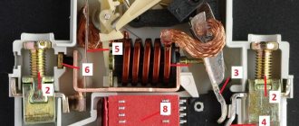
Operating principle of a thermal relay
Today, the most popular are thermal relays, whose action is based on the use of the properties of bimetallic plates. For the manufacture of bimetallic plates in such relays, as a rule, Invar and chromium-nickel steel are used. The plates themselves are firmly connected to each other by welding or rolling. Since one of the plates has a large expansion coefficient when heated, and the other has a smaller one, if they are exposed to high temperatures (for example, when current passes through metal), the plate bends in the direction where the material with a lower expansion coefficient is located.
Thus, at a certain level of heating, the bimetallic plate bends and affects the relay contact system, which leads to its activation and opening of the electrical circuit. It should also be noted that as a result of the low speed of the plate deflection process, it cannot effectively extinguish the arc that occurs when the electrical circuit opens. In order to solve this problem, it is necessary to accelerate the action of the plate on the contact. That is why most modern relays also have accelerating devices that allow you to effectively break the circuit in the shortest possible time.
Starting a single-phase asynchronous electric motor
At their core, compressor motors installed in modern refrigerators are single-phase asynchronous electric motors with a starting winding. Their main components are a rotating rotor and a stationary stator.
The rotor is a hollow cylinder made of conductive material or containing short-circuited wiring.
The stator includes two windings: working (main) and starting (starting). They are mutually located at an angle of 90 degrees, or have the opposite direction of winding - the so-called “bifilar”. Alternating current passing through the main winding creates a magnetic field with a changing vector.
If the rotor is not static, then, according to the law of electromagnetic induction, the motor will develop or decelerate torque, since the slip relative to the forward and reverse magnetic flux is different. Therefore, to maintain movement, alternating current passing through the working winding is sufficient.
If the rotor is stationary, then with the same slip relative to the magnetic fluxes, the resulting electromagnetic torque will be zero. In this case, it is necessary to create a starting torque. This is why a starting winding is needed.
The currents in the windings must be phase shifted, so a phase-shifting element is introduced into the motor - a register, inductor or capacitor. After the rotor reaches the required rotation, the supply of electricity to the starting winding stops.
Thus, to start a single-phase asynchronous electric motor, current must pass through two windings, and to maintain rotor rotation, only through the working winding. To regulate this process, a start relay is installed in the circuit in front of the refrigerator compressor.
Varieties
The relay can be starting or starting protection. The first protects only from exceeding the operating speed, while the second can prevent problems that can arise from excessive temperature increases.
A start-up protection relay is considered a more acceptable option, therefore it is introduced into the design of the Biryusa refrigerator (Indesit, Atlant, Stinol) much more often than a start-up relay. Many people replace the first option with the second immediately after purchasing a new unit.
It is possible to carry out this procedure if you have the appropriate experience and special knowledge, in particular, it is necessary to understand electronics. As a last resort, you can contact a professional.
Source
Measuring insulation resistance with a megohmmeter.
A regular tester will not be able to check the insulation breakdown; it measures resistance using a low voltage of 3-9 V. A megohmmeter allows you to measure resistance with a higher voltage of 200-1000 V. But you still need to first “ring” the windings with a multimeter, since you cannot measure resistance with a megohmmeter with a short short circuit of the winding to the housing.
On the device you can select the voltage with which the resistance will be measured and the time during which the windings will be tested.
It is necessary to measure the resistance between one of the three terminals on the compressor and, for example, a copper tube coming out of the compressor with a voltage of 250-500 V. The resistance should be in the range of 7-10 MOhm. If not, then the compressor also needs to be replaced.
Before taking measurements, carefully read the instructions for your device; high voltage is used, so if used incorrectly, you may receive an electric shock or damage the device.
Troubleshooting and Troubleshooting
There are two ways to determine that the relay is broken:
- Remove the terminals from the trigger mechanism and connect them directly to the electric motor. If the engine runs stably, it turns off stably after 10-20 minutes.
- Connecting the operating relay. If with it the refrigerator starts and stops the engine reliably, then the problem is in the starter mechanism.
Mechanisms with moving parts, contact groups, heating elements are characterized by a standard set of breakdowns:
Contact group jamming
Typical fault signals of this type:
- the electric motor does not turn on at all when the current is connected;
- the engine runs for 10 minutes and turns off;
- non-stop operation of the motor.
A few seconds after the electricity is supplied, the thermal protection is triggered, and the starting relay turns off the current supply. The damage is corrected by restoring the mobility of the rod. The causes of failure are also wear of the part, mechanical damage to the mechanism as a whole or its parts.
Burning, oxidation of contacts
This type of malfunction is detected by disconnecting the relay contacts and connecting the electric motor directly. The stable operation of the latter indicates its serviceability.
You can check the condition of the starting relay with a tester - between the contacts the indicator is zero, indicating the absence of breakdowns. Exceeding the value indicates the need to replace the device. First, you can try to clean the contacts with sandpaper and smooth out the spots.
Heating element burnout
If the compressor does not turn on, the cause may be an open circuit. Attempts to independently correct the breakdown will lead to failure; a complete replacement of the trigger mechanism is required.
Failure of the biometric plate, loss of its main properties
The malfunction is accompanied by the opening of the contact group when the spiral reaches a certain temperature. Short-term switching on and off of the compressor indicates a breakdown of the biometric plate. The only way to fix this is by replacing the relay.
Calling contacts
Malfunctions of the trigger mechanism are detected with a multimeter by ringing three sections:
- Using a measuring device, check the input and output to the working winding for the presence of a break, oxidation of the open contacts, return of the protective mechanism to its original position;
- break of the zero section due to mechanical impact on the circuit;
- Use a multimeter to check the input and output to the starting winding for a break in the current-carrying wire, lack of contact, or open circuit.
Checking the posistor on and off
The part should be checked in a hot and cold state. 2-3 minutes is enough for the posistor to completely cool down. In this state, it must be probed with a millimeter. Absence of indicators or a high value indicates a malfunction of the element. When hot, the posistor displays certain data, which depends on the type of part.