An independent release is not a very suitable device for controlling fire alarm engineering systems.
But its use can be found more and more often - I think because it is the least intellectually expensive.
It’s easiest to add an external control channel to an already established tangle of engineering systems using independent releases.
This is, of course, if you don’t bother with all sorts of integrity controls and feedbacks.
I paid a lot of attention to the issues of using independent releases in articles about methods of controlling the OZK and correctly turning off ventilation, although I was going to go over them in passing, as one of the not the best options.
There seems to be nothing to add to the material presented there. But it seems that the topic will become more and more relevant, and, probably, manufacturers will release more sophisticated equipment for independent releases, and their use will be more formalized in the standards.
So the theory about the use of independent releases will require a separate article. Everything related to the use of releases in fire systems will be monitored here.
For example, now SP 60.13330.2020 “Heating, ventilation and air conditioning” contains:
11.2.3 Turning off ventilation systems in case of fire should be performed centrally, stopping the power supply to the distribution boards of the ventilation systems or individually for each ventilation system. Disabling water-heated supply systems in case of fire should be done individually for each system while maintaining power supply to the frost protection circuits. If it is impossible to maintain power to the frost protection circuits, only the fan should be turned off by sending a signal from the fire alarm system to the supply system fan remote control circuit. When organizing fan shutdown in case of fire using a circuit breaker with an independent trip unit, the signal transmission line must be checked for shutdown.
How to send a signal to an independent release from the APS?
Controlling independent releases using an APS (automatic fire alarm) signal entails a number of requirements.
Moreover, these requirements exist not just for the control method itself, but in general for the entire fire protection system (fire protection system).
The independent release control must contain:
1. Integrity monitoring with alarm about its violation
2. Feedback about the state of the controlled machine.
Hence:
1. The APS must have a controlled output capable of controlling an independent release.
2. The APS must contain a technological loop to monitor the state of the machine, controlled by an independent release.
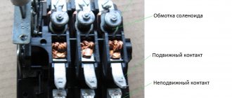
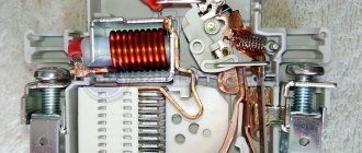
An independent release in circuits used in conjunction with a fire alarm is similar to a valve in fire ventilation systems.
But there is a significant difference - the release has a much lower winding resistance and a much higher current consumption than the valve.
Therefore, the shunt coil cannot be energized forever, like a valve.
There are not so many ways to properly control an independent release with circuit monitoring, if we consider only the correct methods - and in general, I have not seen any methods implemented in reality.
But only three are correct.
Functionality check
Every master sooner or later encounters situations when he needs to ensure the integrity of the releases. This question is of particular interest to amateur installers and novice craftsmen. You can verify that the unit is working in this way:
At the initial stage, a visual inspection is carried out, when the technician carefully examines the entire box of the unit. It is very important to ensure that the body is intact and there are no deformations or cracks on it. Particular attention should be paid to the switch button. It should easily take the required position in any value. At the next stage, the automatic device is checked for timely disconnection of the network when certain unfavorable conditions arise. Specialists carry out this test on a universal unit, where each stage is carefully controlled
Fine tuning allows you to fix the response time of the release from the moment the increased voltage is applied. At the final stage, all that remains is to free the unit from the walls of the housing and monitor it under the influence of powerful equipment. When a current leak is observed, the plate heats up in a matter of seconds and becomes deformed, which signals that the machine lever is turned off.
It is worth noting that any checks of the operation of independent releases for operation should be carried out exclusively in specialized clothing and under the supervision of a qualified specialist.
What can an independent release be used to control?
An independent release can have only one control effect - turn off the power. You can only turn on the power manually.
I have come across the following options for using an independent release to transmit control action from a fire alarm system:
- Turn off the power supply to the general ventilation.
- Turn off the power supply to the OZK valves.
- Turn off the power of the music broadcast monitor.
I can't imagine any other options.
Perhaps for de-energizing electromagnetic locks of emergency exits.
I once saw an attempt at such a solution, but it turned out that electromagnetic locks use 12V power from a redundant power source with a battery - here turning off the 220V power will not help much.
Maximum breaking capacity
Ics/Icu and Icu
But this parameter is the most interesting, although not all manufacturers indicate it. This is the so-called maximum breaking capacity depending on voltage.
In simple terms, the following can be said about Icu. If the short-circuit current passing through the circuit breaker corresponds to this value indicated on the body, then the circuit breaker will successfully complete its task only once.
Then it will no longer be suitable for subsequent use. It will have to be replaced anyway.
If the short-circuit current is equal to the Ics/Icu parameter, then the machine can continue to be used.
These inscriptions are sometimes very important and allow us to evaluate the possibility of using the switching device at different rated voltages. As you understand, the short-circuit currents will differ significantly.
The breaking capacity of the circuit breakers has a quadratic dependence on the supply voltage. Look how significant this difference is.
Therefore, buying a machine for a single-phase 220V is not the same as for a three-phase 380V. Choose the wrong one and expect consequences at the first short circuit:
fire and burnout of the hull
abnormal hum the next time you turn it on, if the machine still “survived”
non-selective operation or contact sintering
It's good if it turns off for you altogether. In fact, the switch in this case turns into a fuse.
But its cost is several times different from the simplest devices with fuse links. The question is, was it worth overpaying?
What types of independent releases are there?
It is not possible to use an arbitrary independent release: the release must be of the same series as the circuit breaker being switched off. Different manufacturers have different series of electrical equipment.
There are independent releases that are triggered by voltages of 12, 24, 60, 110, 220V.
Not all models of independent releases have both high- and low-current versions.
For some independent releases, writing “low-current” does not raise your hand, since the operating current at 12V is stated to be 6A. The “low-voltage” version of the independent release also does not mean 12V - so I may be confused in terms.
Very few models of low-current independent releases have the ability to operate from 12V - 24V independent releases are more common.
A series of electrical equipment, in addition to an independent release, must also contain an additional signal contact.
A release is connected to the machine on the right, and a signal contact is connected to the left.
Or vice versa.
There are also independent releases with an integrated signal contact.
But using this contact to transmit a signal to the alarm system is problematic for some models, since one pole of the contact can be combined with the control line.
The contact is intended for signaling in high voltage circuits. And to stop supplying the control signal after the release is triggered to limit the time the coil is energized.
If any independent release for 220V can be used, then the low-current release must have an operating current of no more than the maximum current of the APS output.
Not all independent releases have accompanying documentation containing the tripping current.
Here are the control signal parameters for the most common “S2C-A” releases for ABB S200 series circuit breakers:
Similar currents are declared for similar independent releases.
Therefore, the question arises when the documentation for the release indicates a significantly lower current - is there a catch here?
Typically, a lower current is required to trip the residual current circuit breakers.
The ABB F2C-A1 release for residual current circuit breakers of the F200 series has the following parameters:
It is already possible to obtain a 12V 0.88A signal from a fire alarm system, but not all equipment can be connected through the F200 series residual current switch.
We will consider specific models of independent releases in the article Independent releases: characteristics and prices.
Principle of operation
To protect the household electrical circuit from adverse effects, craftsmen use high-quality automated switches of a modular design. The great demand for such units has arisen due to the fact that they are compact in size, and are also easy to install and repair.
Externally, such devices are presented in the form of a conventional case made of heat-resistant plastic. The main on and off button is located on the front surface. On the rear panel there is a latch for installation on a DIN rail, and on the bottom and top there are screw terminals.
During normal operation, the unit carries a current less than or equal to the rated value. The top terminal receives power from the external network (this node is securely connected to the fixed contact). Next, electricity is supplied to the main thermal release, and after it - to the lower terminal and the load network connected to it. In emergency situations, the circuit breaker disconnects the protected circuit. An independent device is responsible for performing this function. The reason for this operation may be any emergency situation:
- Voltage overload - short circuit in the circuit.
- The occurrence of overcurrents is an increase in the current strength in the electrical network that exceeds the rated value of the switch.
- Voltage fluctuations.
An example of an incorrect, but very popular way to control an independent release.
The EO project contains the following diagram (can be enlarged):
There are several such circuits in the project for different distribution cabinets - as a result, there are about a dozen independent releases.
The directions of electrical equipment to be disconnected are powered through the following group: automatic + independent release:
Moreover, in the EO project they go further and indicate exactly how the independent fire alarm release should operate:
That is, not a single section of the ventilation shutdown circuits is controlled.
But the EO cabinets have already been ordered, assembled and installed.
The independent release control circuit in a fire alarm project, corresponding to existing electrical equipment, can only look like this:
Here you can see the efforts to adapt it to the requirements of monitoring the integrity of control circuits.
The source of the control signal will be the control and starting unit “S2000-KPB” with monitoring of the integrity of the circuit to the relay amplifier “UK-VK”:
They even introduce monitoring of the state of the ventilation system machine using the signal loop of the Signal-20M device:
But the section “UK-VK” -> Independent release is not controlled in any way.
Discussion on the forum of comments on the use of independent releases.
Installation
Many home-grown electricians believe that installing a machine is not difficult. This is fair, but certain rules must be followed. Circuit breaker releases, as well as plug fuses, must be connected to the network so that when the plug of the circuit breaker is turned out, its screw sleeve is without voltage. The connection of the supply conductor for one-way power supply to the machine must be made to the fixed contacts.
Installation of an electric single-phase two-pole circuit breaker in an apartment consists of several stages:
- securing the switched-off device to the electrical panel;
- connecting wires without voltage to the meter;
- connecting voltage wires to the machine from above;
- turning on the machine.
Fastening
We install a DIN rail in the electrical panel. We cut it to the required size and fasten it with self-tapping screws to the electrical panel. We snap the automatic circuit breaker onto the DIN rail using a special lock, which is located on the back of the machine. Make sure that the device is in shutdown mode.
Connection to the electricity meter
We take a piece of wire, the length of which corresponds to the distance from the meter to the machine. We connect one end to the electric meter, the other to the terminals of the release, observing the polarity. We connect the supply phase to the first contact, and the neutral supply wire to the third. Wire cross-section – 2.5 mm.
Connecting voltage wires
From the central electrical distribution panel, the supply wires are connected to the apartment panel. We connect them to the terminals of the machine, which must be in the “off” position, observing the polarity. The wire cross-section is calculated depending on the energy consumed.
Turning on the machine
Only after all the wires have been installed correctly can the automatic current release be put into operation.
It happens that the constant shutdown of the machine becomes a big problem. Do not try to solve this problem by installing a trip unit with a higher current rating. Such devices are installed taking into account the cross-section of the wires in the house, and, perhaps, a large current in the network is unacceptable. The problem can only be solved by inspecting the electrical supply system of the apartment by professional electricians.
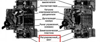
The independent release is an addition to the protective device for the electrical network. It is mechanically connected to the circuit breaker. An independent release performs the function of breaking the circuit when factors are detected that can lead to damage to the line and the devices included in it. These include an increase in current strength above the limit that the cable can withstand, a breakdown of electric current to the ground or the body of a device connected to the circuit, as well as a short circuit. This material will help you understand what circuit breaker releases are, what types of this device there are and what the operating principle of each of them is. In addition, we will tell you how to check the functionality of these elements.
Correct ways to control shunt releases.
Addressable APS device for controlling a 220V valve.
Almost all manufacturers of APS equipment include a module for controlling a 220V drive with control of the drive winding.
The module was designed to control reversible drives of smoke exhaust and air pressure valves - in this article we found out that without such modules the valves will be difficult.
MDU-1 (TD Rubezh), S2000-SP4 (Bolid), BR-4 (PSK-Module), ISM-220 (Sigma), MAKS-U (Unitronic), VERS-ASD(U) (VERS), Z- 027 (Z-Line), BUOK (Forind), BR-1+ (Automation Cluster), BUKP-4 (Gulfstream-Avtomatika), BUEP (TDS Pribor), KUPT-06 (Mirten), IMP3 (Liora), Karat BR4 (Siberian Arsenal), BR-1M (Sys PB), ISM220 ISP4 (Rubicon), MS322 (Plasma-T), MAKS-URP (Unitronic), BKPBKP220/RK (Hephaestus), Astra-BRA (Astra-A Teco).
The cost of the modules is 2160-5500 rubles .
Probably all these modules can be used to control an independent release.
Of course, it’s impossible to just pick and choose the module you like.
The security system used at the facility will already be given as a constant - and only the module that is included in it will need to be used.
Here is a diagram for controlling an independent release and monitoring the state of the machine using the equipment of the S2000-SP4 Bolid addressable valve control modules:
I’m not sure about the value of the resistor in the power circuit, and in general, each module will have its own resistors.
The correct circuit for an EO project using monitored output and state monitored modules is:
The use of high-voltage independent releases entails the need for an addressable alarm system.
APS output expander for controlling 12/24V actuators.
The task of controlling 12/24V actuators has been worked out more thoroughly by manufacturers of fire alarm systems.
This is not surprising, because there are many more types of low-current actuators than 220V actuators.
The same voltage outputs of the OK type (open collector) are suitable here as for controlling warning devices and evacuation displays.
Therefore, the task of organizing a control circuit for a low-voltage independent release seems simpler than for a high-voltage one.
There is just one big BUT - the current consumed by the independent release at the moment of operation is quite large.
And the maximum permissible current of the OK type output is limited.
In common addressable systems, “S2000-SP4” expanders and “RM-4K” addressable modules have a maximum output current of 2A.
The highest output current of all APS devices known to me is 2.5A, and has the addressable module “S2000-SP2 ISP.2”.
In the documentation for different independent releases you can find different cut-off currents.
And theoretically, it is possible to select models of low-voltage independent releases suitable for control from a fire alarm.
Although for most independent releases at 12/24V, the current consumed at cutoff is more than 3A.
But all this should happen with the coordinated work of the designers of the EO and APS sections of the project, which sounds like fantasy.
Moreover, a suitable independent release will not be 12V, but 24V - not a very common voltage for APS in Russia. That is, it is necessary to make a decision in advance that the entire APS system will be 24V.
One more BUT - I have never come across a low-voltage independent release. After all, the configuration of the electrical equipment cabinets is indicated in the EO project - and there will be nothing low-current there and no one will bother about some low-current devices with their stupid fire alarms.
The use of low-voltage independent releases should be included in design decisions at the very beginning of the design.
Special addressable APS module for control and monitoring of an independent release.
I have only seen two such devices.
“ISM220” is an addressable executive module for switching loads in 220 V circuits from the Rubicon system.
With one device at a price of 1600 rubles , we control the independent release, monitoring the integrity of the control circuit, and monitor the condition of the circuit breaker controlled by the release.
But to use this gadget, it is necessary that the Rubicon address system be implemented at the facility.
Addressable control module "MAX-U", costing 2740 rubles .
Costs even more than some valve control modules. The MAKS-URP valve control module, part of the same system, costs only 2160 rubles .
Special devices for monitoring and controlling the 220V actuator.
But what to do if the fire alarm is assembled on one monoblock fire alarm device?
There are no address lines - only analog loops.
How to control an independent release, say, from the Signal-20M device?
It will be necessary to involve specialized equipment for transmitting the control signal for fire protection equipment.
This issue is worked out as fully as possible in the composite PPU (firefighter control device) “Hephaestus”, the modules of which can be used both in a single complex and independently.
For our purposes, the control device and communication lines “UKLSiP(S)220”, which costs only 1085 rubles, .
Then all issues with monitoring the integrity of the control circuit will be removed and even two options for transmitting a fault signal will appear.
The independent release here is an actuator device (ED) that is switched on in case of fire.
If there are several independent releases, then it will be necessary to use the switching and diagnostic device “UK-D (02)” as an intermediary, which costs 1120 rubles.
In these connection diagrams, the valve coil will be the independent release coil.
The devices already have a controlled 2220V output.
There are two control devices that have a power output with integrity monitoring.
VERS-PU has an engineering equipment control relay (RUIO) with a built-in power line control device (UKSL):
The control circuit from the VERS-PU operating manual can be changed using an independent release as a control device.
The device costs 7,100 rubles and is designed to control fire extinguishing - its use in an alarm system does not make sense.
The Sprut-2 control device has 5 (10) 220V power outputs, each with integrity monitoring.
Moreover, if the power control circuit breaks, both the “Alarm” signal and the “Automation disabled” signal can be generated.
These are diagrams from the instruction manuals and in them “Relay K” and “Coil 220V” and there will be an independent release in our case.
This device is intended for use in a fire extinguishing system and its cost of 38,000 rubles makes it impossible to use it as part of an fire extinguishing system.
Sudden shutdown of the mechanism
Experts have recorded a lot of cases when the circuit breaker tripped. This situation requires a quick response from the master. To prevent negative consequences, experts have identified the main list of reasons that provoke the mechanism to turn off:
- Changing previously specified characteristics.
- A sharp decrease in voltage in the electrical circuit.
- Failure of machines or unexpected failure in the system.
- A sharp increase in voltage, a change in current state.
Since there are so many negative factors in the household industry, all modern devices are now equipped with several working mechanisms that allow you to quickly disconnect the network. They are produced from mechanical, electromagnetic or electronic particles. Rational use of such a release helps keep all home appliances safe and sound.
Limiting the duration of the control pulse and monitoring integrity.
If the independent release is connected according to a circuit where the coil is disconnected from the control circuit after activation, then an “Alarm” signal will appear in the fire alarm system as a result of a break in the control circuit.
To avoid this, it is necessary to connect the release coil directly to the PPU, bypassing additional contacts. After all, the activation time of the fire alarm output can be limited when configuring the system.
Perhaps the signal generated by a break will be sufficient to diagnose an emergency situation and there is no need to use an additional signal contact.
Both a break in the control circuit and a physical shutdown of the machine will cause the same “Alarm” signal.
I don’t know if it’s possible to make such a generalization based on GOST R 53325-2012, which says:
7.6.4.1 The device must ensure that the light indication and sound alarm are turned on in the “Fault” mode in the presence of the following events: - detection of a violation of the integrity (break, short circuit) of wired communication lines or a violation of communication between the device and external technical means or between components of the device; Note - It is acceptable that information about a fault in a wired alarm control panel of an addressless control panel is not displayed after receiving information about a fire from this alarm system. — loss or decrease below the permissible value of the power supply voltage at any power supply input; — receiving a fault signal from external technical means interacting with the device; — absence of signals confirming the activation of fire protection means after their activation by the device (in accordance with the operating algorithm of the device); — identification of malfunctions of individual components or units of the device (if the device has a self-test function). 7.6.4.2 Light indication in the “Fault” mode should be carried out by turning on the generalized yellow “Fault” indicator. Interpretation of the direction and type of malfunction should be carried out by yellow single “Fault” indicators in the directions or displayed on the SOTI. Notes 1 Information about the detection of a break or short circuit in a wired communication line may be combined into general information about the malfunction of a given communication line. 2 It is allowed to display information about the malfunction of components or units of the device and software failure using separate generalized single indicators. 3 It is allowed that there is no additional display on the SOTI of information about a power supply fault on the power supply inputs if there are separate indicators displaying the status of each input. 7.6.4.3 Information about the direction and type of fault displayed on the ICT shall be available directly or upon request. 7.6.4.4 Resetting the light indication and sound alarm about a malfunction in devices that have a device for recording and storing event data can be carried out automatically after the malfunction is eliminated. In this case, it must be ensured that information about the registered fault is stored in the recording device. Otherwise, automatic reset of the light indication and sound alarm about a malfunction is not allowed.
How does a voltage relay work?
To understand what is happening with the voltage relay, it is better to know in advance how it will react to various situations, which LEDs light up in which cases. With this knowledge it will be easier to identify triggers. Of course, it is advisable to read the instructions:
- Instructions UZM-16
- Instructions UZM-50TS
- Instructions UZM-51M
- Instruction UZM-3-63
Voltage relay UZM: interpretation of the light indication of modifications UZM-50M and MD, UZM 51 M and MD
When power is turned on
This is what happens when the UZM is started or turned on after the mains voltage has returned to normal.
- Nothing happens for 5 seconds. There is a pause, during which the network parameters and the functionality of the device itself are checked.
- If the voltage is normal, the green LED starts blinking. The duration of the “blinking” depends on the set time delay for turning on the load. Could be 10 seconds or 6 minutes. The delay time is set by the owner at the first start.
- After the delay time has passed, the green and yellow LEDs light up. Green is normal, yellow is the voltage relay is working. If these indicators light up, the UZM has entered operating mode.
The 551 series models have the most management functions
If a long waiting interval is selected - 6 minutes, and there is a need or desire to start the voltage relay faster, you can press the "TEST" button. After the autotest, the relay will turn on immediately.
Sparking in the network
When an arc current is detected in the network, the red “arc” and “fault” LEDs light up and the relay turns off the load. After 30 seconds, an attempt is made to restart with a delay of 10 seconds or 6 minutes (depending on the settings selected by the user). When the emergency situation disappears, the power is turned on. Everything happens as described above: first the green light blinks, after a delay the green and yellow lights up.
UZM 16 (right) is significantly narrower, suitable for use on low-power consumer groups (total voltage no more than 4 kW)
If sparking is detected again within 20 minutes of being turned back on, the device will turn off power for 4 minutes. For the next 20 minutes there is no sparking - the power turns on (all in the same order). Again, an interval of 20 minutes is monitored. If sparking is detected again, the power is turned off and will not automatically turn on again. In this case, you need to click on the “Test” button. If, when turned on manually, the voltage parameters are not within normal limits, the device will not turn on. In general, a reliable algorithm. You just need to remember that if two red LEDs are on, the relay has turned off in an “arc”.
And one more point: if sparking appears after a twenty-minute interval, the operation is considered primary. This means that the entire algorithm is worked out first.
Voltage deviations
While the device is in operation, it automatically - with the help of a varistor - dampens instantaneous voltage surges, smoothing them out. If the deviations are prolonged, the following occurs:
- When the voltage increases: The voltage approaches the upper normal threshold, the red LED begins to blink. “Blinking” begins when the voltage is below the shutdown threshold by 5 V.
- As soon as the parameters are outside the normal limits, the power to the load is turned off, the red LED is constantly on.
- When returning to normal, the power turns on automatically, but only after the holding time has passed (10 seconds or 6 minutes).
- When 5 V remains to the lower shutdown limit, the green indicator starts flashing.
If during the time delay the power again goes beyond the normal limits, the time delay countdown is reset to zero and the corresponding indication lights up.
Manual load switching on/off
If desired, you can turn on the power through the UZM manually - to do this, press the “Test” button. The green and red indicators flash alternately. Manual power is turned on by pressing the button again.
Example of installation in a single-phase network panel
Using the same “Test” button, you can turn off the power. Only it is also turned on manually - by pressing “Test” again and nothing else. Moreover, you need to keep the button pressed for about 2 seconds.
Features of connecting SIP to the input circuit breaker
Self-supporting insulated wire is widely used to transmit electricity to the home network from overhead power lines instead of conventional cable. Despite all the advantages of this conductor, connecting the SIP to the circuit breaker should not be done directly, since during operation the aluminum begins to “float” and the insulation burns. Ultimately, this leads, at best, to failure of the machine, and at worst, to a fire. The easiest way to avoid such trouble is to connect the SIP to the machine through a special adapter sleeve.
This device ensures the transition from aluminum wire to copper. You can buy it in a specialized store.
Step-by-step installation of the machine is shown in the following video:
Briefly about selectivity
According to the rules: the protection must ensure that the damaged section is disconnected during a short circuit at the end of the protected line.
Roughly speaking, you cannot place a circuit breaker with a lower rating above a circuit breaker with a higher rating of the thermal release. That is, a hierarchical chain must be observed. So that when the machine is triggered, only one section of the circuit where the short circuit occurred is switched off.
In the photo above they are 32 and 25, respectively; 32 and 16. Selectivity is maintained. But this version of the shield is not a good example of assembly, this is just to understand the essence. The customer had only 2 circuits (power and light), and he did not want to change the wiring.
Moreover, this also applies to the characteristics of EMR. You cannot place B above a circuit breaker with characteristic C. If you have several powerful consumers, then category D is selected for the input circuit breaker. So that when several installations with a large starting current are started simultaneously, the input circuit does not turn off. Although in those areas the automation will not work, because the short circuit currents did not exceed them.
I hope you found this article on our website helpful!
Phenomena caused by overcurrents
The flow of extreme current causes the following adverse effects:
- Thermal overheating damages the insulation of conductors and operating components and causes fires. The development of this phenomenon is blocked by installing a current protection device with a response speed of ≤ 0.005 s.
- The electrodynamic force deforms and destroys conductive components, causing breakdown of the switching device. The way to combat this is to select components with increased electrodynamic resistance and correct arrangement of parts, excluding mutual EM influence.
- The magnetic field negatively affects the operation of measuring instruments, computers and other precision equipment. The impact of the field is minimized by using screens made of soft magnetic alloys (permalloy, ferrite).
Rating of circuit breakers
Because The purpose of purchasing and installing a machine is to protect the wiring, so first of all you need to focus on its characteristics. The current flowing through the wires heats the cable in proportion to the resistance of its current-carrying core. In short, the thicker the conductor, the greater the current that can pass through it without melting the insulation. In accordance with the maximum value of the current transported by the cable, the rating of the automatic shutdown device is selected. There is no need to calculate anything; the interdependent values of electrical installation devices and wiring by caring electricians have long been summarized in the table: