Electrical power is measured by a wattmeter . The wattmeter consists of a current coil connected in series with the load and another potential coil connected in parallel with the load.
Measuring power in a three-phase system (pictured: traditional power meter)
Depending on the strength of each movement of the magnetic field, the pointer acts on it. True or actual power is directly displayed in the wattmeter. In three-phase systems, power can be measured in several ways. One wattmeter can be used for time measurements.
However, for continuous measurements, a three-phase wattmeter with two elements is used, which shows both balanced and unbalanced loads.
For an unbalanced load, two wattmeters must be used, as shown in Figure 1 .
The total power is calculated by adding the measurement readings given by two wattmeters. The power factor can also be obtained using this method.
When using the two-wattmeter , it is important to note that the reading of one wattmeter should be canceled if the system power factor is less than 0.5 . In such a case, the leads of one wattmeter may have to be reversed to obtain a positive reading. In case of power factor less than 0.5, the data should be subtracted instead of added.
The power factor of a three-phase system, using the two wattmeter method (W1 and W2), can be calculated as follows:
Since the sum and subtraction of counts are performed to calculate the total true power of a three-phase system, the methods shown are not used much in industry.
More three-phase power analyzers are used, which are more user-friendly.
Active power measurement using the three-wattmeter method
The three-wattmeter method is used to measure the power of a three-phase circuit with an unbalanced load in a four-wire system (sometimes used in
three-wire). Each of the wattmeters is connected to one of the phases and measures the power of this phase, and the sum of the readings of all three wattmeters is equal to the active power of the three-phase circuit:
.
Electric current voltage measurement
During the operation of household electrical appliances, situations arise when voltage measurement is required. To check the functionality of sockets, a single-pole indicator is not always enough: it will check for the presence of a phase, but this method will not help to diagnose a break in the neutral wire. The same applies to lighting faults. To determine the integrity of extension cords and power cords of household appliances, the voltage measurement method is more intuitive.
Using a voltmeter, faults such as poor-quality contact connections are detected, which reduces the voltage across the load. The indicator will show the presence of a phase on it, but due to insufficient voltage, the electrical appliance may operate with reduced power (heater) or not work at all (TV, computer, washing machine).
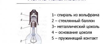
Only measurement can determine the presence of high or low voltage in the electrical network. Overvoltage is a common cause of breakdowns of household appliances. Electrical appliances begin to consume more current and operate in a mode not intended by the manufacturer. The consequence of this is a reduction in work resource. Incandescent lamps with too high voltage not only burn out faster, but also explode when turned on.
Power measurement
Active power in networks is measured using a wattmeter
Digital wattmeter Analog wattmeter
Depending on the load connection diagram and its nature (symmetrical or asymmetrical), the connection diagrams of the devices may vary. Consider the case with a symmetrical load:
Scheme for connecting a wattmeter with a symmetrical load
Here the measurement is carried out in only one phase and then multiplied by three according to the formula. This method allows you to save on instruments and reduce the dimensions of the measuring setup. It is used when greater measurement accuracy in each phase is not needed.
Online electrical magazine
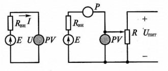
With a symmetrical three-phase load, it is enough to find the power Pf consumed in one phase, because the measured power of the three-phase load P = ZRF. Simple conditions for such a measurement exist when the load is connected in a star to an accessible zero point. In these cases, the wattmeter current circuit is connected in series with one of the load phases (Fig. 1), and the wattmeter voltage circuit is connected to the voltage of the phase whose current passes through the wattmeter. If the zero point is not available or the load is connected in a delta configuration, an artificial zero point is used. This is the name given to the zero point of a star formed from the resistance of the wattmeter voltage circuit rn.W and two other equal additional resistances: rv and rc Fig 2 ). When properly connected to the artificial zero point, the voltage circuit
Rice. 1
The wattmeter is under phase voltage and phase current passes through the wattmeter. Under such criteria, the wattmeter determines the phase power Рф and the power of the three-phase load is again determined by multiplying the wattmeter reading by 3. Typically, the manufacturer supplies the wattmeter with an artificial zero point for measurement in three-phase systems. Power measurements in three-phase, three-wire systems with unbalanced loads are almost always performed using the 2-wattmeter method (Fig. 3). A specific feature of this method is that not only with an asymmetrical, but even with a symmetrical load, the readings of two wattmeters are almost always unequal, and the readings of one of the wattmeters can become negative. The power of a three-phase system in this case has to be determined as the algebraic sum of the readings of 2 wattmeters.
Rice. 2
The validity of this method is proven on the basis of the equations of instantaneous power, expressed in terms of second values of voltages and currents. The instantaneous power of any phase is equal to the product of the instantaneous values of phase voltages and current, and the instantaneous power of a three-phase system is equal to the sum of the instantaneous phase powers. For example, when connecting with a star
Р = uAiA + u В i В + uCiC
But according to Kirchhoff’s first law, when connected by a star without a neutral wire
iA + i B + iC and, as follows,
iC = – ( iA + iB ) = 0
Substituting this value into the power equation, we get:
p = (uA - uC) i A + (u B - is ) i B
The phase voltage difference is equal to the corresponding line voltage:
uA - uC = uAC , u B - is = u B C based on what
p = uAC i A + u B C i B
As follows, the power of a three-phase system can be
expressed as the sum of two products, and these
two products can be measured by two wattmeters,
included in accordance with the method diagram (Fig. 3).
Rice. 3 Scheme of the 2-wattmeter method
There is no need to particularly justify the validity of the 2-wattmeter method for a delta connection, because at certain values of line voltages and currents, the power does not depend on the method of connecting the load.
Let us note a peculiar feature of the two-wattmeter methods: the system of linear voltages in the usual sequence is denoted iAV , ivs, iSA, and the equation of this method includes the voltage uAS. This rearrangement of indices means that in relation to the first wattmeter it is necessary to change the voltage phase by 180°. To do this, it is enough to connect the “beginning” (the clamp with the asterisk sign) of the voltage circuit of the first wattmeter with wire A, and the “end” of this circuit (the clamp with the rated voltage indicated) with wire C.
The dispersion of the power of a three-phase system between the readings of two wattmeters depends mainly on the magnitude and sign of the phase shift cf. Let us trace this dependence in a simple case with a symmetrical load. If, instead of instantaneous power, we substitute the active (average) power of a three-phase system into equation (101), then we need to replace the second values of voltage and currents with effective ones and enter into the equation the cosines of the phase shifts between the appropriate voltages and currents. Thus, the power equation will take the following form:
p = p1 + p2 = uAC i A cos f1 + ivs i B cos f2
With a symmetrical load, the linear currents are
i A = i B = I l
are equal to each other in the same way as line voltages
uAC = ivs = il
Fig. 4 Vector diagram for the 2-wattmeter method
In Fig. 4 a vector diagram of a three-phase system is constructed, on which the vector uAC is constructed equal in magnitude and opposite in direction to ICA
Based on this diagram, the phase shift angle between the vectors uAC and i A and the phase shift angle ph2 between the vectors ivs and i B ph1 = ph – 30o and ph2 = ph + 30o, respectively As follows, the readings of 2 wattmeters, which make up the power of a three-phase system, will be expressed as follows:
р = р1 + р2 = silt I l cos ( f – 30o) + silt I l cos ( f + 30°)
This expression indicates that with a symmetrical load, the readings of the wattmeter are equal only at φ = 0. If φ >60o, then the needle of the second wattmeter deviates beyond the zero of the scale, and in order to read the reading of the second wattmeter in such conditions, it is necessary to switch (i.e., swap places in the diagram) terminals of the device voltage circuit. Often, to change the phase of the current by 180° in the voltage circuit, a special toggle switch is built into the wattmeter housing. The readings of the second wattmeter after switching should be considered negative and, in order to find the power of a three-phase installation, these readings must be subtracted from the readings of the first wattmeter.
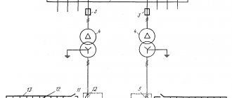
To measure power in three-phase four-wire systems, the 3-wattmeter method is simple. The current circuit of one of the wattmeters is connected to any of the linear wires, and the voltage circuit of each of the wattmeters is connected between a suitable linear wire and the neutral wire of the system (Fig. 5).
Fig. 5 Diagram of 3 watt meters
With this connection, any of the wattmeters determines the power of one phase of the system. As follows, the active power of the entire three-phase system will be equal to the usual sum of the readings of 3 wattmeters:
p = p1 + p2 + p 3
In industrial installations, three-phase current wattmeters are widely used on distribution boards. They represent two (for a three-wire system) or three (for a four-wire system) measuring mechanisms connected by a common axis and thus influencing a common pointer. These measuring mechanisms are connected to a three-phase circuit according to the 2-wattmeter method or the 3-wattmeter method.
Formulas for reactive power
Reactive power = √ (Apparent power 2 – Active power 2)
kvar = √ (kVA 2 – kW 2)
Apparent power (S)
Apparent power is the product of voltage and current, ignoring the phase angle between them. All power in the AC network (dissipated and absorbed/returned) is total power.
The combination of reactive and active power is called apparent power. The product of the effective voltage value and the effective current value in an alternating current circuit is called apparent power.
It is the product of voltage and current values without taking into account the phase angle. The unit of apparent power (S) is VA, 1 VA = 1 V x 1 A. If the circuit is purely active, the apparent power is equal to the active power, and in an inductive or capacitive circuit (if there is reactance), the apparent power is greater than the active power.
Characteristics of a three-phase system
Electric current power formula
A three-phase power supply system is characterized by several voltage and current values. It all depends on between which points of the circuit the measurements are made:
- between the phase wire and the neutral – phase voltage Uph;
- between individual phases – linear Ul.
The relationship between these parameters:
Ul=√3∙Uф.
With symmetrical load distribution, the currents in all wires are equal. In a four-wire circuit (with a grounded zero), there is no current in the neutral conductor, so even if the zero is broken, the network continues to function normally.
In the case where the energy consumption differs between phases, some current flows in the neutral wire. A complete break in the neutral conductor causes a phase imbalance, so the voltage on the wires can change in the range from zero to linear.
Consequences of increasing neutral resistance
The reactive nature of the load is taken into account by the power factor cosϕ. This value comes from the theory of complex numbers, which are used when it is necessary to calculate the parameters of alternating current circuits. In the case of an active load, cosϕ = 1, but the more reactive the consumers are, the more the coefficient decreases, showing how the real power decreases relative to the total.
Important! Therefore, to correctly calculate and reduce the load on generating equipment, power factor correctors are installed in reactive circuits. Circuits with a corrector bring the cosϕ coefficient closer to unity.
Active power measurement in three-phase circuits
Measurement of active power in three-phase circuits is carried out using three, two or one wattmeters, using various circuits for their connection. The connection diagram of wattmeters for measuring active power is determined by the network diagram (three or four wires), the phase connection diagram of the receiver (star or triangle), the nature of the load (symmetrical or asymmetrical), and the availability of the neutral point.
With an asymmetrical load in a four-wire circuit, the active power is measured with three wattmeters (Fig. 19), each of which measures the power of one phase - phase power.
Example of calculating power indicators
What is power factor
The simplest example is the calculation of energy consumption by a symmetrical load. How much electricity will a three-phase asynchronous motor consume, connected to a network with a linear voltage of 380 V, and consuming a current of 10 A in each phase? Power factor cosϕ=0.76. Then the power consumption is:
P=√3Uл∙Iл∙cosϕ=√3∙380∙10∙0.76=5000 VA.
More complex calculation of a household network:
- Phase voltage – 220 V;
- Line consumption – 10 A, 5 A, 2 A;
- The first two phases are connected to an active load (electric stove, kettle);
- The third is loaded with fluorescent lamps with cosϕ=0.5.
Ptotal=Uа∙Iа∙cosϕа+ Ub∙Ib∙cosϕb+ Uc∙Ic∙cosϕc=220∙10+220∙5+220∙2∙0.5=3520 VA.
Using an online calculation calculator, you can get rid of most errors and reduce calculation time. You just need to enter the data correctly according to the current parameters
Application
Scope of application of DPM
Designed for use in energy management systems where there are high demands on the quality of energy management.
- Electricity consumption analysis systems.
- In medium and low voltage distribution boards.
- Energy management systems.
- In reactive power compensation systems.
Comments on the article “Three-phase network power”
In the power formula for a triangle connection, it is necessary to add that Iph = ROOT of I LINEAR, which means the final formula takes the form almost the SAME as for the power for a star connection - P = ROOT of THREE * Uphase * I linear * cos f
What does U phase = U linear. That is, in both cases the power formula is the same.
Tell me, we measured the current using clamps on the conductors of the 3rd pole circuit breaker and got the values. How to calculate power through. square root? or as for single-phase P=UI
It all depends on how much power you want to calculate. If complete, then yes, S = UI. For other powers, you need to use different formulas.
Add a comment Cancel reply
- Magnetic starters – 133 870
- Logic elements and their circuit implementation – 107,358
- What is the difference between NPN and PNP transistors? – 97 328
- What is active, reactive and apparent power – 93,294
- The relationship between phase and line voltages. Rated voltages – 84 615
- Input and distribution of electricity in an apartment building – 83,531
- What are power supply reliability categories? – 81 176
- Three-phase network power – 69,686
- 11 myths about Bluetooth 5.0 – 69,101
- Mechanical characteristics when braking synchronous machines – 65,289