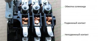
Thermal release, overload current
If you choose a circuit breaker for home electrical wiring, then we can say that we protect the electrical wiring. After all, the choice is made based on the maximum value that a cable to which several outlet groups are connected will withstand. Well, or dozens of light bulbs and chandeliers.
In short, the thermal release (TR) reacts to long-term overloads in the electrical wiring. This characteristic is indicated on the machine itself by a number (as in the photo) of the rated current. It's simple.
Rated current is the highest value of current that a conductor of a certain cross-section can withstand and operate in normal mode for an unlimited amount of time.
That is, exceeding the rated current by 10-20% for longer than 5-10 minutes. The higher the build quality, the faster it will react and protect the connected consumers and the wiring itself. When choosing a device, you need to include a 10% margin to the calculated current of the electrical installation.
Standard choice for houses and apartments: 10 for lighting, 16 for socket groups and a washing machine, 25 and 32 for powerful installations, such as electric stoves. How to calculate is described in detail in the article - how to choose a circuit breaker.
Rated current of circuit breaker
The rated current of the circuit breaker is indicated on the front part of the circuit breaker, accessible and clearly visible during operation. The designation of the rated current of a circuit breaker is made by a number, usually following the Latin letter indicating the time-current characteristic of the circuit breaker. The number indicating the rated current of the circuit breaker means that the circuit breaker is designed to protect electrical wiring whose operating current is greater than or equal to the rated current of the circuit breaker.
Characteristics of the electromagnetic release
An electromagnetic release (EMR) disconnects the load at short-circuit currents (quickly exceeding the value by 3-20 times the rated value). This is an emergency situation that, if the errors are calculated incorrectly, can burn out the entire electrical wiring in a second.
The second situation: if you select it incorrectly, then starting some installations with a high starting current (such as washing machines with motors in their design) will be impossible. Each time you turn it on, the protection will be triggered and a section of the circuit will be disconnected. Therefore, this characteristic should not be chosen rashly.
The characteristics of the EMR machine are indicated by the letter following the number (photo). Which means the multiple of excess of the rated current at which the short-circuit current protection will operate. That is, the electromagnetic release will turn off the power. The meanings of these letters are as follows:
- A: 1. They are installed to protect expensive microelectronics that do not have starting loads.
- B: Guaranteed to work at currents 3-5 more than the rated current. Placed for lighting.
- C: 5-10. The most common characteristic for home wiring.
- D: 10-20. Most often used for engines.
Even a chandelier with fluorescent lamps has its own starting current, which is approximately 2 times higher than the rated current. Therefore, for lighting we select category B. For socket groups C. Characteristic D is selected in rare cases, during preliminary calculations. In rare cases, it is selected for the introductory machine to achieve selectivity.
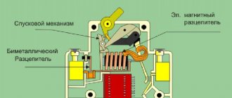
What it is
The machine protecting the network has 2 tasks:
- detect too much current in time;
- break the chain before damage occurs.
The main task of a circuit breaker is to respond to the appearance of excessive current and de-energize the network. Two types of currents have a dangerous effect on the network:
- overload current arising due to the inclusion of a large number of devices in the network;
- overcurrent due to short circuit.
Modern electromagnetic devices easily and accurately detect short-circuit current and turn off the load. There are more problems with overload current. They do not differ much from the nominal value and occur without consequences for a certain period of time. The problem is that there is a load current limit that harms the network.
There are 3 types of releases in circuit breakers - mechanical for manual switching, electromagnetic for responding to short circuit currents and thermal for overload protection.
Application area
Circuit breakers are used wherever electronic devices are located. They are also installed in domestic conditions (to protect apartments, private houses), at manufacturing enterprises, in business centers, and shopping malls.
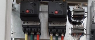
Briefly about selectivity
According to the rules: the protection must ensure that the damaged section is disconnected during a short circuit at the end of the protected line.
Roughly speaking, you cannot place a circuit breaker with a lower rating above a circuit breaker with a higher rating of the thermal release. That is, a hierarchical chain must be observed. So that when the machine is triggered, only one section of the circuit where the short circuit occurred is switched off.
In the photo above they are 32 and 25, respectively; 32 and 16. Selectivity is maintained. But this version of the shield is not a good example of assembly, this is just to understand the essence. The customer had only 2 circuits (power and light), and he did not want to change the wiring.
Moreover, this also applies to the characteristics of EMR. You cannot place B above a circuit breaker with characteristic C. If you have several powerful consumers, then category D is selected for the input circuit breaker. So that when several installations with a large starting current are started simultaneously, the input circuit does not turn off. Although in those areas the automation will not work, because the short circuit currents did not exceed them.
I hope you found this article on our website helpful!
Circuit breaker current limit
The circuit breaker current limit is the maximum electric current that can be switched off by the circuit breaker. The current limit of the circuit breaker is also called PKS and is indicated in the markings on the front surface. The marking of the maximum current of the circuit breaker can be indicated in amperes, designated as 3000, 4500, 6000 or 10000, while the figure of the maximum current of the circuit breaker is indicated in a rectangle, without indicating the dimension.
Due to the lack of dimension, the number in the rectangle is sometimes perceived incorrectly and is interpreted as, for example: the permissible number of switches on and off of the machine, the guaranteed number of operations, and other incorrect options.
The current limit of a circuit breaker determines the use of such a circuit breaker depending on the maximum possible short circuit current that can occur in the protected electrical wiring. For most household electrical installations, a PKS of 4500 Amps is quite sufficient, since the state of household electrical networks does not allow the short circuit current to exceed a value of 3000 - 4000 amperes, however, in some cases of short circuits, a current exceeding 4500 amperes can flow through the circuit breaker. In the case of using a 4.5kA circuit breaker, with such an excess of current, the circuit breaker will not be able to turn off the power, since the contact group, under the influence of such a high current, will overheat and weld - burn. The mechanical force stored in the release mechanism is not enough to tear the welded contacts away from each other and the machine will not turn off the power, maintaining the short-circuit current, which will lead, at best, to melting and damage to the wiring, and at worst, to a fire.
Devices for constant voltage circuits
The design of alternating voltage electromagnetic coils is different from direct voltage.
To protect such devices, special circuit breakers are used. They differ from ordinary ones by the polarity marking on the body, which must be observed. The operating principle of both devices is the same. Used in control and power circuits that are powered by batteries.
Current limiting class
When overcurrents occur, the insulation heats up sharply. At the maximum current value, the machine disconnects the circuit. During this time, the insulation may be damaged, so another characteristic is introduced that controls the current.
The current limiting class affects the safety of the entire circuit. Physically, this is the period of time during which the contacts open and the arc in the extinguishing chamber is extinguished. There are 3 classes:
- Class 3 – the fastest, blanking time is 2.5 ms;
- Class 2 – extinction time 6-10 ms;
- Class 1 – blanking time exceeds 10 ms.
On the device this value is indicated in a black square. Class 1 is not indicated on the device.
Trips and politics
With a high degree of probability, I can assume that the trip brothers became victims of the collapse of the USSR and here’s why.
It seems that the main developer of the head of PUE 3.1 was NIPI Tyazhpromelelektroproekt named after. F.B. Yakubovsky. He also published a Manual for Chapter 3.1 of the PUE, where, among other things, he gave explanations for paragraph 3.1.11. At the very end of this explanation there is a Note that I will quote here:
9. Note
In Chapter 3.1 of the PUE, there is a different approach to circuit breakers with an unregulated and adjustable characteristic inversely dependent on the current: in the first case, the sensitivity of the protection is associated with the rated current of the release, in the second - with the starting current of the release (operation current).
This difference in approaches is caused by the concern that for an regulated characteristic, the operating current ratio with respect to the rated one can be significantly increased compared to the ratio adopted for an unregulated characteristic. In fact, for all switches in the table. 1, this multiplicity varies within relatively small limits (1.2-1.35), and most importantly, is in no way related to the ability to regulate the characteristics. Therefore, it is difficult to find strict logic in the requirements of the PUE, and in our examples, classifying the characteristics of circuit breakers as adjustable or unregulated is rather arbitrary.
To eliminate this ambiguity, in the new edition of Chapter 3.1, prepared for the 7th edition of the PUE, the requirements for protection sensitivity are associated with the tripping current of the release, regardless of whether the characteristic of the circuit breaker is adjustable or unregulated
I have highlighted the most significant phrases in bold - these edits are mine. The rest is as it is.
What can I say? We all make mistakes, the main thing is to correct it in time. But it seems that the time turned out to be inappropriate for such events. Look at the title page of this Manual and the year of its release.
It seems to me that all these initiatives with the reunion of the brothers-disconnectors remained an idea on paper. The year 1991 was not the most successful in terms of the development of our electric power industry in general and the improvement of technical documentation in particular.
And now, if you strictly follow the PUE, then the calculation turns out to be crazy, but if you still take the starting current for all releases, then there is simply nothing to refer to. This is such a sad story.
But if you think that this is the only problem in Chapter 3.1, then you are very mistaken. This is not even the main problem) There is at least one more, and it’s simply epic!
If you want to hear a new story on this topic, then upvote this article, write comments and share it on social networks. If there is interest, I will write)
Successful calculations and approvals to everyone!
Ultimate switching capacity
This is the maximum value of overcurrent that the machine will withstand without losing its functionality.
The most common breakers are sized 4500, 6000 and 10000 A. Overcurrent occurs when a short circuit occurs in the circuit. It flows between phase and zero when the insulation is broken, bypassing the consumer. The current strength depends on the resistance of the wiring, so it is necessary to take into account the material from which it is made. For houses with old aluminum wiring, it is better to use machines with a limit of 4500 A. For copper wiring, machines with a limit of 6000 A are used.
Characteristics of switches and their groups
There are several important characteristics of an automatic machine based on which an automatic machine is selected for different loads. One of them is the response characteristics of circuit breakers.
Graph No. 1 shows the difference in time current characteristics of the 3 main groups of machines
The characteristic curve shows how the response time of the machine varies from the ratio of the current through the contacts of the machine to its rated value. The dependence line is displayed graphically. For example, circuit breakers of the same rating with different characteristics of the circuit breaker curves have different shutdown times. Also in graph No. 1, the coverage areas of the thermal protection and electromagnetic protection of the circuit breakers are marked with rectangles.
Criteria for selecting a three-phase switch
Before purchasing, it is worth considering all the parameters that the input device will have.
Leakage current
The body is marked with the Greek letter “delta”. The current leakage of a private house is about 350 mA, of a separate group of devices - 30 mA, lamps and sockets - 30 mA, single links - 15 mA, boiler - 10 mA.
Varieties by current
The machine has indexes A (triggered by DC leakage) and AC (triggered by AC leakage).
Number of poles
Single-pole circuit breaker is used for one phase
Depending on the number of poles, you can purchase a three-phase switch:
- single-pole type of devices for protecting one cable and one phase;
- two-pole, represented by two devices with a common switch - switching off occurs when the permissible value of one of them is exceeded, at the same time the neutral and phase in a single-phase network are cut off;
- a three-pole device that provides interruption and protection of the phase circuit - they are three devices with a common activation/deactivation handle;
- a four-pole device, which is mounted only on the input of a three-phase switchgear, breaks all three phases and the working zero. Breaking the grounding of the protection is unacceptable.
Installation location
For domestic use, a 3-phase electric circuit breaker marked C is intended for 25 A. In this case, it is better to install products C50, C65, C85, C95 at the input. For sockets or other points - C 25 and C 15, for lighting - C 12 or C 17, for an electric stove - C 40. They will operate when the current readings are 5-10 times higher than the nominal value.
Checking the functionality of the release
The main parameter during testing is the compliance of the declared parameters of the mechanism with its technical indicators at the time of testing. The first thing that is checked when assessing performance is the time elapsed from the start of supplying the critical load to the machine until the circuit is released. The parameters of the normal time range are indicated by the manufacturer in the technical documents attached to the device. In case of non-compliance with the standards, the switches are replaced with new ones.
Such checks are necessary to ensure stable and safe operation of the device, and neglecting them can be fatal.
Block contacts
Block contacts produced by ETI series 2159311(NO+NC), 2159032(NO) and 2159312(NC) are used for remote signaling of the device status. In addition to the AB series ETIMAT 10 (80...125 A), an additional block contact 2159121 (NO+NC) can be added.
For the ETIMAT P10 and ETIMAT P10 DC series, an additional signal contact PS/SS ETIMAT P10/11 768900101 with 1NC and 1NC/NO is used. This accessory can work as a contact block - to signal the position of the contacts, or as a signal contact - to signal an emergency shutdown. The selection is made manually. To do this, turn the screw on the housing with the corresponding marking. The controlled AB has a special hole for the trip rod. The contact block is connected to the switch using two brackets and a needle in the auxiliary contact handle. Triggering occurs using a needle or other disconnecting element.
Block contacts from EATON Z series are characterized by several mounting options (ZP - mounting with snaps, Z - mounting with screws), changing the functions of the contacts, the presence of self-cleaning contacts (ZP-NHK), the ability to install two contact blocks on one circuit breaker (ZP -IHK – 1NO, 1NC, ZP-WHK – 1 changeover contact).