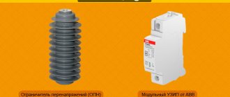
Limiter protection classes
In the voltage range below 1000 V, limiters are divided into 4 classes, designated by alphabetical letters: A, B, C and D.
- Class A limiter is not used in domestic installations, but is used to protect power lines.
- Class B protector is used to protect against high voltage surges, such as those caused by lightning striking a power line.
- A Class C suppressor is designed to provide surge protection for slightly lower line voltages. Class B and C protective devices are usually installed in household switchgear.
- A class D protector is used for direct protection of selected electrical devices that are sensitive to impulse noise and surges in a 220 V network. It is mounted in a distribution panel, behind a socket in an electrical box, or directly in the protected device.
Each protection device limits the electrical potential to only a certain level. The closer the equipment is to class A, the higher the power. For example:
- Class A will reduce the voltage level to 6 kV,
- Class B will reduce the voltage level to 2.5 kV,
- Class C will reduce the voltage level to 1.5 kV,
- Class D will reduce the voltage level to 0.8 kV.
Therefore, limiters of individual classes should be used in cascade, gradually reducing the level of the maximum voltage. That is, if there is one switchgear in the house, we use both B and C class protective devices (there are 2 in 1 B + C protective devices).
If the building is multi-storey, class B protective devices should be used in the main distribution panel, and class C limiters should be used in the distribution panels in individual apartments.
If the device connected to the outlet is sensitive to voltage surges, we can also use Class D suppressors. We do not have access to Class A suppressors; this is a concern for the power company.
Since we will be looking at home wiring, the article will focus on class B and class C (types I and II) protective devices.
Installation recommendations
If you follow the recommendations for installing and connecting a surge suppressor, the device will guarantee the safe operation of household equipment.
- It is important to have a very reliable grounding. Protection with an unreliable grounding loop, even with a not very large surge in the voltage pulse, will lead to an emergency in the form of burnt electrical appliances and the panel itself.
- It is necessary to ensure that the protection class of the SPD matches the installation location of the shield. If the shield is located outdoors, and the device is intended to work indoors, then at best it will fail, at worst it will harm the home electrical network.
- To ensure reliable protection, in some cases it is necessary to install SPDs of different protection classes.
- Not every protective device is suitable for a specific type of grounding of the home electrical network. You should carefully study the technical documentation of the device you are purchasing so as not to waste money on a fairly expensive device.
- It is important to connect the circuit correctly, without any violations. If you do not have the skills of an electrician, you should not take on the job. A qualified specialist will do it correctly, without much difficulty.
Lightning strikes, downed power lines or accidents at transformer substations cannot be predicted. Installing an arrester will protect you from unexpected troubles.
Installing a surge suppressor
A standard B or C (possibly B+C) arrester consists of two components:
- Limiter base
- Replaceable insert with protective element
The basis
The base of the protective device is mounted on a TS35 DIN rail. It has two clamps. Connect the phase (L) or neutral (N) wire, which may have too much electrical potential. On the other side, connect the PE protective conductor, which is connected to the protective line of the switchgear.
The protective conductor should have a minimum cross-section of 4 mm2, but it wouldn't hurt to go larger. After all, there is a possibility that a very high current will flow.
There are 3 contacts under the PE terminal. As standard, the kit includes a plug that is inserted into the right place and allows you to connect the wires. Thanks to these clips, it is possible to remotely notify in case of damage to the insert or its burnout. This signal can be connected, for example, to the input of the alarm control unit (see diagram). In this case, the control panel will be informed that the insert is damaged by opening the electrical circuit between the red and green wires.
Insert
The insert contains all the most important elements thanks to which the defender functions correctly:
- Class B (Type I) - the main element is simply the spark gap.
- Class C (type II) - here the varistor is the main element.
▍Act one. We attract lightning and send it to the ground.
Everyone has probably heard and seen about lightning rods (they are also lightning rods, and they are also lightning rods):
Lightning rod on the dome of a wooden church.
. This is not necessarily a spire sticking into the sky; for power lines it is made in the form of a lightning protection cable, which is taller than all others and does not have insulators:
A pair of lightning protection cables over power lines.
. The principle is simple - it is a conductor electrically connected to the ground, and placed as high as possible. If conditions for a lightning strike are created in this area, then most likely (but not 100% guaranteed!) the discharge will occur precisely in the grounded conductor, and not in surrounding objects. The cross-section of the conductor is selected sufficient to conduct the discharge to grounding without damage. The lightning rod acts as an “umbrella”, taking on all the elements. The analogy with an umbrella becomes even more obvious if you look at the formulas for calculating the radius of the area protected by a lightning rod - the higher the lightning rod, the larger it is. It is worth noting that there are several methods for determining the area protected by a lightning rod, and even among lightning protection specialists there is no unanimous opinion which method is more accurate. For example, a photo from the Encyclopedia Britannica shows two approaches to calculating the protected area - a cone along the height of the lightning rod and the rolling sphere method.
Areas protected by a lightning rod.
Source. The lightning rod turned out to be damn important for use in wooden houses. If previously a lightning strike on the roof could start a fire (the energy of the discharge on the way to the ground was partially converted into heat, setting everything on fire), then redirecting the discharge along a metal pin into the ground saved from such terrible consequences. And if you look closely, all modern buildings and structures have a lightning rod on the roof. And particularly important objects may generally have quite complex lightning rod designs. In those places where proper grounding is difficult to do (on a rock, sand), lightning protection becomes a completely non-trivial task. This is what lightning rods look like at a gas station in Nigeria:
The developers decided that lightning rods of this shape work better.
Source But, if the method worked flawlessly, the text would break off at this point. It was cut short before the advent of sensitive and delicate equipment.
How does a surge protector work?
Protection is provided by devices powered by 220V network cords connected to the arrester in the distribution box. This applies to both phase and neutral conductors (depending on the selected type of protection).
The general rule is to connect the phase conductors and possibly the neutral conductor on one side of the protective device, and the protective conductor on the other side.
When the system voltage is normal, the resistance between the wires is very high, on the order of several GigaOhms. Thanks to this, current does not flow through the arrester.
When a power surge occurs, current begins to flow through the limiter to ground.
In class B safety devices, the main element is the spark gap . During normal operation, its resistance is very high. In the case of a spark gap, this resistance is gigantic, since the spark gap is actually an open circuit. When lightning strikes a component of an electrical installation directly, the spark gap resistance drops to almost zero due to the electrical arc. Due to the appearance of a very high electrical potential in the spark gap between the previously separated elements, an electric arc is created.
Due to this, for example, a phase wire in which there is a large voltage surge and a protective wire create a short circuit and a large current flows directly to the ground, bypassing the internal electrical installation. After the discharge, the spark gap returns to its normal state - that is, it breaks the circuit.
Useful: Replacing an electrical outlet in an apartment with your own hands
A class C limiter has a varistor inside . A varistor is a specific resistor that has a very high resistance at a low electrical potential. If a voltage surge occurs in the system due to a discharge, its resistance quickly decreases causing current to flow to ground and a similar situation as in the case of a spark gap.
The difference between Class B and Class C is that the latter is capable of limiting voltage surges with a lower potential than a direct lightning strike. The disadvantage of this solution is the rather rapid wear of the varistors.
The main thing in surge suppressors, regardless of the class used, is the installation of grounding with very good parameters, that is, with very low electrical resistance. If this resistance is too high, the overvoltage current (caused by a lightning strike) can flow through the electrical system instead of the protector and leave behind burnt equipment that is currently plugged into 220-volt outlets.
Principle of operation
In pulsed transients, the voltage changes much faster than the current. Therefore, the classic current circuit breakers known to everyone will be ineffective here. The presence of a limiter with a semiconductor element having a nonlinear current-voltage characteristic provides electrical network devices with protection from high voltage pulses.
As can be seen from the graph, at the nominal voltage value the resistance of the semiconductor (it is called a varistor) is quite large and the current passing through it is practically zero (zone 1). When a varistor is exposed to high-voltage pulses (zone 2), its resistance decreases sharply, approaching almost zero (zone 3). In this embodiment, the limiter varistor will act as a shunt connection that takes on the entire current load, which is directed to the ground loop.
Connection diagram of the limiter to the network
How to connect a limiter to a home panel? Let's start with the basics. We have a single-phase network and a single-module arrester. We want to protect the phase wire with it. Network type – TN-S.
We connect the phase power conductor directly to the arrester and connect the arrester on the other side to the PE terminal block.
But this home switch has nothing more than a surge limiter. Let's add the missing elements.
As you can see, installing a surge suppressor does not affect the further organization of components in the home switchboard. The connection of the residual current device and circuit breakers is carried out in the same way.
In general, in switchgears, surge arresters of class B, C or B + C are installed before the circuit breaker (or circuit breakers) and overcurrent fuses. But the limiter is the first element underlying the protection of a house or apartment.
Gas arrester
Gas arresters are components filled with an inert gas (Fig. 2). The arrester body is made in the form of a ceramic tube, the ends of which are closed with metal plates and act as electrodes.
Figure 2 – Block diagram of a gas discharger
Three-phase installation
In a three-phase circuit, the width of the limiter and the number of protected connections increase. However, the operating principle of the limiter remains unchanged. The most commonly used three-layer system protective devices operate in a 4 + 0 system, which means connecting the following lines to the arrester:
- 3 phase wires
- 1 neutral wire
Each of the wires to be protected has equal rights, that is, possible overvoltages are eliminated by supplying current to the protective installation and, as a result, to the ground.
Of course, for TN-C installations (installations without a separate protective conductor) it is possible to purchase protective devices with only 3 protected connectors. Then, from the bottom side, connect the limiter to the PEN (protection neutral) strip.
SPD: features of selection and application
Even short-term impulse voltage surges, several times higher than the nominal voltage, can cause irreparable damage to expensive electrical equipment and electronics, or even cause a fire. Overvoltage in networks can occur due to thunderstorms, accidents or transients. For example, pulse overvoltages can result from lightning hitting a lightning protection system or power line, switching powerful inductive consumers such as electric motors and transformers, or short circuits.
Surge suppressor parameters
Before you go to the store and buy this device, you need to know the following:
- The number of modules (terminals) depends on the type of your network. 1 module can be purchased when there is a single-phase TN-C system. 3 modules when the installation is in a three-phase TN-C network and 4 modules when the network is three-phase in TN-S or TT.
- Class (type) – you can choose between classes B, C or B + C. If you are not sure that a type B limiter is used in front of your apartment, you should choose a B + C solution. Otherwise, a type C limiter will be sufficient.
- The rated voltage at which the limiter operates.
- Uc is the operating voltage of the protector, that is, the maximum voltage level that will lead to operation.
- In is the rated current of the limiter, that is, what current can flow through the arrester in the event of a short circuit.
- Imax is the current that the arrester is capable of accepting during an atmospheric discharge. Please note that both values (In = 30,000A and Imax = 60,000A) will be relatively large in relation to the current during normal operation of appliances in the house.
- Up – the voltage to which it decreases in the event of a rupture. For example, if the potential reaches a voltage of 10,000 V in the event of a surge, the final value is reduced to 150.
Specifications
In addition to the design, an equally important factor when choosing the required (pulse) surge suppressor (SPD) is its following main technical parameters.
- The maximum operating voltage that acts on the surge arrester indefinitely without affecting its performance.
- The maximum voltage acting on the surge arrester for the time specified by the manufacturer without causing any damage to it.
- By applying operating voltage to the ends of the arrester, the current passing through the insulation is measured. This parameter is called leakage current. Its value in a good condition of the limiter tends to zero.
- Discharge current - its value determines the identity of the surge limiter in protection against various factors causing voltage surges: lightning, electromagnetic, switching.
- Ability to withstand emergency operation while maintaining the integrity of all structural elements.
Is it worth using a network limiter?
Every electrician wonders whether it is worth buying a surge arrester at all. After all, this is not the cheapest element of electrical installation. Theoretically, during renovation or construction of wiring from scratch in an apartment or house, the cost of 3,000 rubles (in the case of a 4-module protector) is a drop in the ocean of expenses. In practice, a protective block will not always have the opportunity to prove that it is needed. Even if it does work, voltage reduction may not always protect sensitive electronic devices (class D protection is better).
Nevertheless, the editors of 2Skhema.ru strongly recommend equipping the network with this equipment. If it protects even one valuable device, the costs will immediately pay off, and even more than that!
Appearance and dimensions of surge arresters 6-750 kV
Suspended limiters for voltage classes 6-35 kV are shown in Figure 7.
Figure 7 – suspended surge arrester: a) 6 kV surge arrester; b) surge arrester 10 kV; c) surge arrester 35 kV
The appearance and dimensions of the 110-220 kV suspended surge arrester are shown in Figure 8.
Figure 8 – suspended surge arrester: a) 110 kV surge arrester; b) surge arrester 220 kV
The appearance and dimensions of surge arresters 330-750 kV are presented in Figures 9 and 10.
Figure 9 – a) surge arrester 330 kV; b) surge arrester 500 kV
Figure 10 – 750kV surge arrester
What it is?
Surge surge protectors, as the name suggests, are high-voltage equipment that is designed to protect electrical devices from voltage deviations significantly exceeding the nominal values. As a rule, these strong deviations are pulsed in nature, which is why such devices are called surge voltage limiters (SVO).
Previously, valve-type arresters were used for this purpose - devices that were based on spark gap technology. Nowadays, technology has improved significantly, and now a surge suppressor, which can also be called a surge arrester, is successfully used. Only it no longer has a spark gap.
To more accurately present the whole picture, let’s consider what could be the reasons for such voltage drops.
FAQ
- Does it make sense to install a fuse on the neutral line?
Yes, when power lines are broken, the phase often ends up on the neutral or ground, in this case two different phases can come to the socket; this is 380V. Lightning can hit the neutral conductor or grounding, which is hundreds of thousands of volts.
- If hundreds of thousands of volts pass through the SPD during a voltage surge, what wire cross-section should be used?
The wires are installed with the calculated cross-section for the entire house on the input circuit breaker; if the SPD is installed on a separate group of lighting or sockets, then the cross-section is the same as in the wires of this group. At the input it is usually 10 -16 mm2,
Lighting groups 07-1.5 mm2, sockets 2.5 - 4 mm2.
11. Arresters 6 kV, 10 kV, 35 kV, 110 kV, 220 kV
The main characteristics of 6-220 kV arresters are given in tables 2 and 3.
Table 2 - Technical characteristics of 6 kV, 10 kV arresters
| Parameter | Unit | RVO-6 N | RVO-10 N |
| Mains voltage class | kV | 6 | 10 |
| Highest permissible voltage | kV | 7,5 | 12,7 |
| Breakdown voltage at a frequency of 50 Hz in dry conditions and in the rain: | |||
| no less | kV | 16 | 26 |
| no more | kV | 19 | 30,5 |
| Pulse breakdown voltage at pre-discharge time from 2 to 20 μs, no more | kV | 32 | 48 |
| Remaining voltage at a wave of 8 μs, no more: | |||
| with current amplitude 3000A | kV | 25 | 43 |
| with current amplitude 5000A | kV | 27 | 45 |
| Leakage current, no more | µA | 6 | 6 |
| Current carrying capacity: | |||
| 20 current pulses with a wave of 16/40 µs | kA | 5,0 | 5,0 |
| 20 square wave current pulses with a duration of 2000 µs | A | 75 | 75 |
| Leakage distance of external insulation, not less | cm | 18 | 26 |
| Permissible wire tension, not less | N | 300 | 300 |
| Height, no more | mm | 294 | 411 |
| Weight, no more | kg | 3,1 | 4,2 |
Table 3 - Technical characteristics of 35 kV, 110 kV, 220 kV arresters
| Parameter | Unit | RVS-35 RVS-35 T1 | RVS-110M RVS-110M T1 | RVS-220M RVS-220M T1 |
| Mains voltage class | kV | 35 | 110 | 220 |
| Highest permissible voltage | kV | 40,5 | ||
| Breakdown voltage at a frequency of 50 Hz in dry conditions and in the rain: | ||||
| no less | kV | 78 | 200 | 400 |
| no more | kV | 98 | 250 | 500 |
| Pulse breakdown voltage at pre-discharge time from 2 to 20 μs, no more | kV | 125 | 285 | 530 |
| Remaining voltage at a wave of 8 μs, no more: | ||||
| with current amplitude 3000A | kV | 125 | 315 | 630 |
| with current amplitude 5000A | kV | 130 | 335 | 670 |
| Leakage current, no more | µA | 143 | 367 | 734 |
| Current carrying capacity: | ||||
| 20 current pulses with a wave of 16/40 µs | kA | 10,0 | 10,0 | 10,0 |
| 20 square wave current pulses with a duration of 2000 µs | A | 150 | 150 | 150 |
| Leakage distance of external insulation, not less | cm | 115 | 345 | 690 |
| Permissible wire tension, not less | N | 300 | 500 | 500 |
| Height, no more | mm | 1280 | 3100 | 4620 |
| Weight, no more | kg | 73 | 175 | 497 |
Long-term overvoltages and dips due to lack of voltage
As a rule, the cause of long-term overvoltages in networks is a break in the neutral wire. In this case, the load on the phase conductors is distributed unevenly, which leads to phase imbalance when the potential difference shifts to the conductor with the maximum load.
Thus, the uneven three-phase current, acting on the neutral cable, which is not grounded, contributes to the concentration of excess voltage on it. This process will continue until the fault is completely eliminated or until the line finally fails.
Another dangerous network condition is a dip or lack of voltage. Similar situations arise very often in rural areas. The essence of the phenomenon is a voltage drop below the permissible value. Such subsidence poses a serious danger and a real threat to equipment. Many modern devices are equipped with several power supplies, and insufficient voltage leads to a short-term shutdown of one of them.
As a result, an immediate reaction from the electronic equipment will follow in the form of an error displayed on the display and a complete stop of the work process. If a similar situation arises with the heating boiler in the winter season, then heating of the house will be stopped. The problem can be eliminated with the help of a stabilizer, which fixes such sag and raises the voltage to the nominal value.
