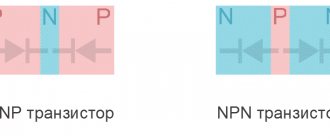
Radio amateurs need to receive various radio signals. This requires the presence of a low-frequency and high-frequency generator. Often this type of device is called a transistor generator due to its design feature.
Operation of a transistor generator
Additional Information. A current generator is a self-oscillating device created and used to generate electrical energy in a network or convert one type of energy into another with a given efficiency.
Slide captions:
Slide 1
Transistor generator. Self-oscillations. L St. L E B Passed Kartashova Yana Student 11 a class MBOU Secondary School No. 64
Slide 2
A self-oscillatory system is an oscillatory system that performs undamped oscillations due to the action of an energy source that does not have oscillatory properties. For example: watches, internal combustion engine, wind instruments.
Slide 3
Feedback in a self-oscillation generator must satisfy two conditions: 1. the energy from the source must flow in time with the oscillations in the circuit. 2. the energy supplied from the source must be equal to its losses in the circuit. L St. L E B K
Slide 4
The oscillatory system consists of: Energy source Battery of galvanic cells K valve Transistor Oscillatory system Oscillatory circuit Feedback Inductive - through coils
Slide 5
Oscillations in the circuit occur with high frequency. The capacitor replenishes energy losses only at those moments when its polarity coincides with the polarity of the source. At those moments when the polarities are opposite, it will discharge through the source. LC _ + + _ _ +
Slide 6
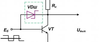
Obviously, a prerequisite for obtaining undamped oscillations in the circuit is the replenishment of energy losses precisely at moments when the polarity of the capacitor and the source coincide and disconnecting the capacitor from the source at other times. As a device capable of performing such a function, you can use a transistor, through which the capacitor of the oscillating circuit will be connected to the current source. a high-speed device until a signal is applied to the base - no current flows through the transistor, the capacitor is disconnected from the source when a signal is applied - current flows through the transistor and the capacitor is charged from the source?
Slide 7
As a device capable of “giving a signal” at the right moment, a feedback coil is used, one end of which is connected to the base and the other to the emitter (inductive connection) L St. L E B K We have obtained a system in which undamped oscillations can be generated by replenishing energy losses from a source within the system itself.
Slide 8
Process in a self-oscillating system: After charging the capacitor, its upper plate is charged positively, the bottom plate is charged negatively. The capacitor begins to discharge through the coil. The current gradually increases in the first quarter of the period, then decreases, generating an alternating magnetic field that penetrates the turns of the coil L. In the coil L St, which is inductively connected to the coil of the circuit, a magnetic field appears, having the same direction, and an induced current appears, directed from the emitter to the base. The transistor passes current to the capacitor, in which at this time another induction current flows, coinciding in direction with the original one. All energy losses are replenished, the signs of the plate charges change to the opposite L St. L E B — I K + —
Slide 9
The current through the capacitor now flows in the opposite direction, increasing in the first quarter and decreasing in the second. The magnetic field generated by the current penetrates the turns of the circuit coil, and, consequently, the inductively connected coil L St.. An induction current appears in the feedback coil, directed from base to emitter, as a result of which the base potential is higher and current does not flow to the capacitor. Only an induction current flows in the capacitor, coinciding in direction with the current at the beginning of the half-cycle. The capacitor is recharged, the signs of the plates are reversed. L St. L E B + — + — + —
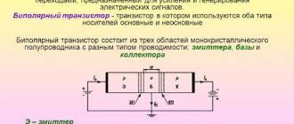
Generation mechanism
A simplified diagram can be represented as follows:
Instead of a transistor, we put a certain “element with negative resistance”. In essence, it is a reinforcing element. That is, the current at its output is greater than the current at the input (so that’s tricky).
An oscillatory circuit is connected to the input of this element. Feedback is supplied from the output of the element to the same oscillatory circuit (via capacitor C2). Thus, when the current at the input of the element increases (the loop capacitor is recharged), the current at the output also increases. Through feedback, it is fed back to the oscillatory circuit - “feeding” occurs. As a result, undamped oscillations settle down in the circuit.
Everything turned out to be simpler than steamed turnips (as always).
Voltage converter 3-12V/+15V, -15V
Transistor generator
Voltage converter, the circuit of which is shown in Fig. 10, differs in that in it the load circuit is galvanically isolated from the control circuit. This allows you to obtain several secondary stable voltages. The use of an integrating link in the feedback circuit improves the stabilization of the secondary voltage.
Rice. 10. Circuit of a stabilized voltage converter with a bipolar output 15+15V.
The conversion frequency decreases almost linearly as the supply voltage decreases. This circumstance enhances the feedback in the converter and increases the stability of the secondary voltage.
The voltage on the smoothing capacitors of the secondary circuits depends on the energy of the pulses received from the transformer. The presence of resistor R2 makes the voltage on storage capacitor C3 dependent on the pulse repetition rate, and the degree of dependence (slope) is determined by the resistance of this resistor.
Thus, using the trimming resistor R2, you can set the desired dependence of the change in the voltage of the secondary windings on the change in the supply voltage. Field effect transistor VT2 is a current stabilizer. The efficiency of the converter can reach 70... 90%.
The instability of the output voltage at a supply voltage of 4 ... 12 V is no more than 0.5%, and when the ambient temperature changes from -40 to +50 ° C - no more than 1.5%. Maximum load power is 2 W.
When setting up the converter, resistors R1 and R2 are set to the minimum resistance position and equivalent loads RH are connected. A supply voltage of 12 V is supplied to the input of the device and, using resistor R1, a voltage of 15 V is set across the load Rн. Next, the supply voltage is reduced to 4 V and resistor R2 is used to achieve an output voltage of 15 V. By repeating this process several times, a stable output voltage is achieved.
Windings I and II and the magnetic circuit of the transformer are the same for both converter options. The windings are wound on an armored magnetic core B26 made of 1500NM ferrite. Winding I contains 8 turns of PEL wire 0.8, and Winding II contains 6 turns of PEL wire 0.33 (each of windings III and IV consists of 15 turns of PEL wire 0.33 mm).
Function transistor generator
Functional generators based on self-oscillation transistors are invented to produce methodically repeating pulse signals of a given shape. Their form is determined by the function (the name of the entire group of similar generators appeared as a result of this).
There are three main types of impulses:
- rectangular;
- triangular;
- sawtooth.
A multivibrator is often cited as an example of the simplest LF producer of rectangular signals. It has the simplest circuit for DIY assembly. Radio electronics engineers often begin with its implementation. The main feature is the absence of strict requirements for the ratings and shape of transistors
This occurs due to the fact that the duty cycle in a multivibrator is determined by the capacitances and resistances in the electrical circuit of transistors. The frequency on the multivibrator ranges from 1 Hz to several tens of kHz
It is impossible to organize high-frequency oscillations here.
Obtaining sawtooth and triangular signals occurs by adding an additional circuit to a standard circuit with rectangular pulses at the output. Depending on the characteristics of this additional chain, rectangular pulses are converted into triangular or sawtooth pulses.
Picture on electrical diagrams
Blocking generator: operating principle
First, let's consider obtaining a sinusoidal type of signal. The most famous oscillator based on a transistor of this type is the Colpitts oscillator. This is a master oscillator with one inductance and two series-connected capacitors. It is used to generate the required frequencies. The remaining elements provide the required operating mode of the transistor at direct current.
Additional Information. Edwin Henry Colpitz was the head of innovation at Western Electric at the beginning of the last century. He was a pioneer in the development of signal amplifiers. For the first time he produced a radiotelephone that allowed conversations across the Atlantic.
The Hartley master oscillator is also widely known. It, like the Colpitts circuit, is quite simple to assemble, but requires a tapped inductance. In the Hartley circuit, one capacitor and two inductors connected in series produce generation. The circuit also contains an additional capacitance to obtain positive feedback.
Transistor generator circuits
The main area of application of the devices described above is medium and high frequencies. They are used to obtain carrier frequencies, as well as to generate low-power electrical oscillations. Receiving devices of household radio stations also use oscillation generators.
All of the listed applications do not tolerate unstable reception. To do this, another element is introduced into the circuit - a quartz resonator of self-oscillations. In this case, the accuracy of the high-frequency generator becomes almost standard. It reaches millionths of a percent. In receiving devices of radio receivers, quartz is used exclusively to stabilize reception.
As for low-frequency and sound generators, there is a very serious problem here. To increase the tuning accuracy, an increase in inductance is required. But an increase in inductance leads to an increase in the size of the coil, which greatly affects the dimensions of the receiver. Therefore, an alternative Colpitts oscillator circuit was developed - the Pierce low-frequency oscillator. There is no inductance in it, and in its place a quartz self-oscillation resonator is used. In addition, the quartz resonator allows you to cut off the upper limit of oscillations.
In such a circuit, the capacitance prevents the constant component of the base bias of the transistor from reaching the resonator. Signals up to 20-25 MHz, including audio, can be generated here.
The performance of all the devices considered depends on the resonant properties of the system consisting of capacitances and inductances. It follows that the frequency will be determined by the factory characteristics of the capacitors and coils.
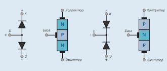
Important! A transistor is an element made from a semiconductor. It has three outputs and is capable of controlling a large current at the output from a small input signal. The power of the elements varies. Used to amplify and switch electrical signals.
Additional Information. The presentation of the first transistor was held in 1947. Its derivative, the field-effect transistor, appeared in 1953. In 1956 The Nobel Prize in Physics was awarded for the invention of the bipolar transistor. By the 80s of the last century, vacuum tubes were completely forced out of radio electronics.
Operating principle
Pulse generator
The category of generators that use self-powering usually includes the following names of original designs, which have recently been increasingly mentioned on Internet pages:
- Various modifications of the Tesla free energy generator;
- Vacuum and magnetic field energy sources;
- So-called “radiant” generators.
Among fans of non-standard solutions, much attention is paid to the famous circuit solutions of the great Serbian scientist Nikola Tesla. Inspired by his proposed non-classical approach to using the capabilities of the e/magnetic field (the so-called “free” energy), natural scientists are looking for and finding new solutions
Known devices, which, according to the generally accepted classification, belong to such sources, are divided into the following types:
- The previously mentioned radiant generators and the like;
- Blocking system complete with permanent magnets or transgenerator (its appearance can be seen in the figure below);
Blocking generator
- So-called “heat pumps”, operating due to temperature differences;
- A vortex device of a special design (another name is the Potapov generator);
- Electrolysis systems for aqueous solutions without pumping energy.
Of all these devices, the rationale for the principle of operation exists only for heat pumps, which are not generators in the full sense of the word.
Important! The existence of an explanation of the essence of their work is due to the fact that the technology of using temperature differences has long been used in practice in a number of other developments. It seems much more interesting to get acquainted with a system that works on the principle of radiant transformation
It is much more interesting to get acquainted with a system that operates on the principle of radiant transformation.
Varieties
On the vast Internet you can also find the following implementation of the same generator:
The circuit is called "capacitive three-point". The operating principle is the same.
In all these schemes, the generated signal can be removed either directly from the collector VT 1, or use a coupling coil connected to a loop coil for this purpose.
Push-pull generator for hard workers
What is a generator
The other generator that we will consider is also a push-pull generator. However, it contains an oscillatory circuit, which makes its parameters more stable and predictable. Although, in essence, it is also quite simple.
Here he is
What do we see here?
We see the oscillatory circuit L1 C1, And then we see a pair for each creature: Two transistors: VT1, VT2 Two feedback capacitors: C2, C3 Two bias resistors: R1, R2
An experienced eye (and not a very experienced one) will find in this circuit similarities with a multivibrator. Well, that’s how it is!
What is special about this scheme? Yes, because due to the use of push-pull switching, it allows you to develop double power, compared to circuits of 1-cycle generators, at the same supply voltage and provided that the same transistors are used. Wow! Well, in general, she has almost no flaws
Generation mechanism
When the capacitor is recharged in one direction or the other, current flows through one of the feedback capacitors to the corresponding transistor. The transistor opens and adds energy in the “right” direction. That's all the wisdom.
I have not seen any particularly sophisticated versions of this scheme...
Now for a little creativity.
Background
A non-working scanner fell into my hands just now; there was no point in repairing it, so it was used for spare parts. I removed the CCFL (cold cathode fluorescent lamp) lamp and converter from it and decided to play with them.
But the converter turned out to be inoperative, and since I really wanted to play around, I decided to restore it. Since, when replacing a burnt-out transistor, the tracks on the Chinese board began to peel off, I decided to make my own, at the same time study the principle of operation in more detail and write an article on Habr, maybe someone will be interested.
The device of a simple generator
The simplest generator is an ordinary rectangular frame, which is placed between magnets with different poles. To relieve stress from the rotating frame, slip rings are used.
In the automotive industry, electromagnets are used - inductors or windings of copper wire. When electric current passes through the winding, the latter is saturated with electromagnetic properties. A battery is used to excite the winding.
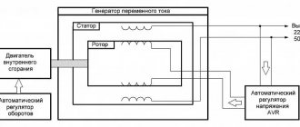
The device of a car alternator
A car generator consists of a housing with covers that have holes for ventilation. The rotor is installed in bearings 2 and rotates in them. The rotor is driven by a belt drive (the belt is put on a pulley). The rotor acts as an electromagnet (winding). Current is supplied to the winding using two copper rings and graphite brushes, which are connected to an electronic regulator. The electronic relay regulator is responsible for the output voltage, which should be within 12 Volts, regardless of the rotation speed of the generator drive pulley. The relay regulator can be built into the housing, or it can be located separately.
Stator - consists of three copper windings that are connected in a triangle. A rectifier bridge is connected to the connection points of the windings, which consists of 6 semiconductor diodes, which are used to convert alternating voltage to direct voltage.
A generator (from Latin generator means “producer”) is a device that generates electricity, produces products, or converts one type of energy into another.
A car generator is a device that converts the mechanical energy of rotation of the crankshaft of a car engine into electrical energy.
A car generator is used to power consumers of electricity, such as the ignition system, lighting devices, the car's on-board computer, diagnostic systems, as well as to charge the battery.
The reliability of the generator depends on the uninterrupted operation of other vehicle systems and its other components. The power of a modern car generator is 1 kW.
The principle of operation of a car generator
The first automobile generators were DC generators. They required a lot of attention, which was due to frequent maintenance and monitoring of the operation of the device.
Then diode rectifiers were invented, which significantly increased the service life of the generator and increased its service life. Generators with diode current rectifiers began to be called alternating current generators. The alternator required less materials to produce, making it lighter and significantly smaller, while its efficiency increased, providing a more stable current output.
Modern foreign cars use synchronous three-phase alternating current generators, and a three-phase Larionov rectifier is used as a rectifier.
From turning the key to releasing voltage...
When the ignition key is turned to the operating position, power is supplied to the excitation winding and the generator begins to supply current to the load. The voltage stabilizer, which is included in the brush assembly of the generator, is responsible for controlling the current in the excitation winding. The voltage stabilizer is powered from a rectifier.
The generator rotor is driven from the crankshaft through a pulley by means of a V-belt. An electromagnetic field is created in the field winding, which induces an electric current in the stator phase windings.
The output current is intermittent and depends on the engine speed, so a voltage stabilizer is used to stabilize it.
The voltage of the on-board network in a working system should be in the range of 13.8-14.2 V, which will ensure normal charging of the battery.
On large vehicles, high-power 24 V automobile generators are used.
Electrolysis of water
In cases where we are talking about new types of electric generators, we should not forget about such a promising direction, which is the study of the electrolysis of liquids without the use of third-party sources. Interest in this topic is explained by the fact that water is inherently a natural, reversible source. This follows from the structure of its molecule, which, as is known, contains two hydrogen atoms and one oxygen atom.
During the electrolysis of water mass, corresponding gases are formed, which are used as complete substitutes for traditional hydrocarbons. The fact is that when gaseous compounds interact, a water molecule is again obtained, plus a significant amount of heat is simultaneously released. The difficulty of this method is to ensure that the required amount of energy is supplied to the electrolysis bath, sufficient to maintain the decomposition reaction.
This can be achieved if you change the shape and location of the electrode contacts used, as well as the composition of the special catalyst with your own hands.
If the possibility of exposure to a magnetic field is taken into account, then it is possible to achieve a significant reduction in the power consumed for electrolysis.
Note! Several similar experiments have already been carried out, proving that, in principle, it is possible to decompose water into components (without additional pumping of energy). All that’s left to do is to master the mechanism that assembles atoms into a new structure (re-synthesizes a water molecule)
All that’s left to do is master the mechanism that assembles atoms into a new structure (re-synthesizes a water molecule).
Another type of energy transformation is associated with nuclear reactions, which, for obvious reasons, cannot be carried out at home. In addition, they need enormous material and energy resources sufficient to initiate the process of nuclear decay.
These reactions are organized in special reactors and accelerators, where conditions with a high magnetic field gradient are created. The problem that specialists interested in cold nuclear fusion (CNF) face is finding ways to maintain nuclear reactions without additional input of third-party energies.
In conclusion, we note that the problem with the devices and systems discussed above is the presence of strong opposition from corporate forces, whose well-being is based on traditional hydrocarbons and atomic energy. CNF research, in particular, has been declared a wrong direction, as a result of which all centralized funding has been completely stopped. Today, the study of the principles of obtaining free energies is supported only by enthusiasts.
Add a link to a discussion of the article on the forum
RadioKot >Competitions >Congratulate Kot as a human being 2022! >
| Article tags: | Add a tag |
Universal Signal Generator
Author: Integrator Published September 20, 2017 Created using KotoEd. Participant of the Competition “Congratulate the Cat as a Human 2022!”
One day, taking out of the box a piece of a breadboard with tangled wires and an NE555 soldered to it, I realized that I needed a normal signal generator. I wanted to get both good functionality and simplicity of the circuit using available components. There were several interesting circuit solutions found on the Internet. However, upon closer examination, they all revealed their shortcomings. As a result, it was decided to make our own generator, with the maximum possible number of functions, so that it would be enough, if not for all, then for most of the needs.
It differs from similar devices assembled on the basis of AVR by a wide selection of generated signals, more accessible and cheaper components and single-polar power supply. Of course, it cannot be compared with factory instruments, but it may be useful in a home laboratory.
Characteristics.
Waveform:
- sinus
- triangle
- saw
- reverse saw
- ECG
- noise
- meander
- high frequency
- PWM (rectangle with adjustable duty cycle)
- specially shaped pulses
- TV signal(bands)
Frequency:
- Sine, triangle, saw, reverse saw, ECG: 1Hz - 111.1KHz
- Square wave: 1Hz - 500.0KHz
- Square Wave(High Frequency): 1MHz, 2MHz, 4MHz, 8MHz
PWM:
- 1Hz-99KHz
- fill factor 1% - 99%
- possibility of external synchronization
Special shape pulses:
- Tmin. = Trise+Ton+Tfall+Toff = 8µs
- Tmax = Trise+Ton+Tfall+Toff = 4000000us
- number of pulses 1 - 65535
- possibility of triggering by external impulse
Supply voltage 12V Signal amplitude 0 - 5V Offset -3 - 3V DAC bit size 8bit Sampling frequency 1.78MHz
The generator has 2 outputs - A, D and input - E. Signals in sine, triangle, saw, reverse saw, ECG, noise, TV, pulse modes are output to output A.
Output D is digital; it outputs signals in PWM, square wave, and high frequency modes. There is a protective resistor at the output.
Input E is used to trigger PULSE mode and for synchronization in PWM mode. There is a protective resistor and a zener diode at the input; there is no pull-up to the power supply.
All set parameters are saved in the controller’s non-volatile memory after the generator is started.
Operating modes.
After turning on the device, the display in the top line shows the current operating mode and status (on or off). The bottom line indicates additional parameters. When you press the mode button, the operating mode of the device changes. When you press the set button, the mode for setting parameters for the current mode is activated. The on/off button starts or turns off the generator. Switch F turns the analog filter on output A on and off.
Sine (SINE), triangle (TRIANGLE), saw (SAWTOOH WAVE), reverse saw (RSAWTOOH WAVE), ECG (ECG) . The signal of the selected shape is generated by the tabular method. To switch to the frequency input mode, you need to press the set button. In this mode, the top line shows the current frequency, and the bottom line shows the step of the number being set. The value is set using the +/- buttons, the step can be changed with the mode button. Upon completion of the input, you need to press the set button again, after which the generator will switch to the main mode.
Sine 1KHz, 5V, offset 1V.
Saw 21KHz.
triangle 1KHz.
ECG 1KHz
Noise (NOISE). Generates noise, uses the standard library function rand(), has no configurable parameters.
Meander (SQUAREWAVE). Generates rectangular pulses with a duty cycle of ~50% using the DDS method.
High frequency (HIGH SPEED). Generates high frequency rectangular pulses with a duty cycle of ~50%. It has only 4 frequency values: 1MHz, 2MHz, 4MHz, 8MHz.
PWM (PWM). Generates rectangular pulses with adjustable duty cycle by dividing the clock frequency. In this mode there are 3 adjustable parameters, the transition between them is carried out sequentially by pressing the set button.
F - frequency is set similarly to the previous modes.
DC - duty cycle can be set in the range 1-99% in 1% increments using the +- buttons.
PWM 21KHz, 80%.
EXT SYNC - external synchronization can have 3 values, which are selected with the +- buttons:
- NO – absent, the generator will work all the time after pressing the on button.
- HIGH – the generator will operate when there is a high level at input E.
- LOW - the generator will operate when there is a low level at input E.
PWM 21KHz, 80%, external sync. E=H.
Pulses of a special shape (PULSE). Allows you to generate pulses with a specified period of linear rise/fall of the signal level. Has 6 customizable parameters.
Trise — pulse rise period 2 — 1000000 μs; Ton - high level period 2 - 1000000 µs; Tfall—pulse decay period 2—1000000 μs; Toff - low level period 2 - 1000000 μs, set with the +- buttons, the step is selected with the dir button.
Trise=Ton=Tfall=Toff=100µs, N=ND
N – number of pulses, set using +- buttons, step selected by mode button.
- Range 1 - 65535, after startup the generator will output the set number of pulses to output A.
- ND – not defined, the generator will work all the time after pressing the on button.
Trise= 3μs,Ton=Tfall=Toff=100μs, N=3
TRIGGER - starting the generator with an external pulse at input E. Values selected using the +- buttons:
- NO – absent, the generator will work all the time after pressing the on button.
- RISE – after pressing the on button. the generator will start only on the edge of the pulse at input E. While waiting, W:R will be shown in the top line of the display
- FALL - after pressing the on button. the generator will start only when the pulse at input E falls. While waiting, W:F will be shown in the top line of the display
TV (TV). Generates an analog video signal - vertical stripes. For proper operation, you need to set the offset to 0V, amplitude to 5V. Output A is connected to the video input of the TV.
Reset settings.
It may be necessary if your EEPROM has not been flashed or some kind of collapse occurred during the setup process and now the device shows something terrible. To reset the settings in a de-energized generator, press the set button, then turn on the power and, without releasing the button, wait for 5 seconds. After this, the settings in the EEPROM are overwritten to the default ones.
Scheme.
The entire digital part is implemented in the Atmega8A microcontroller operating at a frequency of 16 MHz. A resistive R2R DAC is connected to the microcontroller, producing an analog signal. From the output of the DAC, the signal goes to the buffer amplifier on U2B. Then it passes through a 2nd order active low-pass filter, assembled according to the Butterworth circuit on U2A, with a cutoff frequency of 300 KHz. The filter was calculated using the online calculator from AD.
Switch SW5 allows you to select whether to record a signal directly from the repeater or passed through a low-pass filter. Next in the circuit is an inverting amplifier with an adjustable gain of 0 - 0.5. This coefficient was not chosen by chance. The fact is that the lower supply voltage of the op-amp TL082 should be 1.5V lower than the output voltage. Those. with an amplitude of 5V, the supply should be -6.5V, which would require a change in the voltage converter circuit. The signal then goes to the second inverting amplifier, which shifts the level relative to the bias voltage, controlled by resistor RV1. It also restores the signal amplitude, which was previously reduced in U3B.
Signals in PWM and square wave (high frequency) modes are generated by a microcontroller timer-counter by dividing the clock frequency. In meander mode - using the DDS software method.
To save I/O ports, the display is connected according to a write-only circuit, with the RW pin grounded. Lines D4 – D7 have a dual purpose; in addition to transmitting data to the display, control buttons are connected to them. To avoid short circuits, when pressing the button and transmitting data at the same time, protective resistors are installed. Data transfer and reading of button states occurs sequentially.
Also on the board there are contact pins for the Rx and Tx lines, to which the software UART 19200 8b1 is output. In the current firmware version, this interface works only for output.
Via the V_GEN line, the controller produces rectangular pulses with a frequency of ~20 KHz, which are supplied to the voltage converter. It generates the -5.6V needed to power the op-amps.
A little theory.
The generator uses the direct digital frequency synthesis (DDS) method. The algorithm from the AVR DDS signal generator V2.0 device was taken as a basis and modified. In particular, by replacing reading table values from flash with a buffer in RAM, it was possible to reduce the work cycle time by 1 clock cycle. Which led to an increase in the sampling frequency from 1.6 to 1.78 MHz. Based on it, an algorithm was written for generating a rectangle and pulses with an arbitrary linear rise and fall time.
The simplest digital-analog generator on an MK is quite easy to make. A table of values of an analog signal (for example, a sinusoid) for 1 period is taken. And it is serially output to the MK port to which the DAC is connected. The frequency of the output signal will be equal to:
FOUT = FCLK/C; FCLK is the frequency at which output to the port occurs (sampling frequency), C is the number of values in the table.
The main disadvantage of this method is its unsatisfactory frequency tuning ability. Since the sampling frequency is divided by an integer, the tuning step will be variable, and the smaller the division factor, the larger the relative step size.
With direct digital synthesis, the sampling rate remains constant. A special variable is introduced into the algorithm, which stores the current value of the signal phase, called the phase accumulator. In the specific example, its size is 24 bits. The main code of the algorithm is written in assembler:
;the address of a buffer in RAM is loaded into register Z, containing a table of 256 values of one period of the generated signal; for the algorithm to work correctly, the buffer address must be aligned at 0x100h, i.e., start at 0xXX00h; in this case, the buffer is located at address 0x0100 ldi zh , 0x01 ldi zl, 0
;registers r18, r19, zl constitute a 24-bit phase accumulator; the highest 8 bits are also an index in the signal table eor r18, r18 ;resetting the accumulator eor r19, r19 ;resetting the accumulator
;in registers r22, r23, r24 there is a 24-bit value of the phase increment - M
1: add r18, r22 ;add accumulator with M adc r19, r23 ;add accumulator with M adc zl, r24 ;add accumulator with M ld r0, z ;load value from table at address Z out _SFR_IO_ADDR(R2RPORT), r0 ;output values in the DAC sbic _SFR_IO_ADDR(BTN_PIN), START ;condition for interrupting the cycle, if the button is pressed we exit rjmp 1b ;jump to the beginning of the cycle
In a cycle that rotates at a predetermined frequency FCLK, a certain constant number is added to the phase accumulator, which is called the phase increment - M. In this case, the value of the accumulator increases at a constant speed, and its highest 8 bits are used as an index in the table of analog signal values. The battery overflow period will be equal to one period of the generated signal. In this case, the period itself may not be a multiple of the clock frequency, see the graph.
FOUT = M * FCLK/N where FOUT is the output frequency, FCLK is the sampling frequency, M is the phase increments, N is the maximum value of the phase accumulator.
the sampling frequency is FCLK = F_CPU/NUM_CYCLES, where F_CPU is the processor clock frequency - 16 MHz, NUM_CYCLES is the number of machine cycles per cycle pass - 9 FCLK = 16000000/9 = 1777777Hz
The minimum signal frequency will be at M = 1 FMIN = 1 * 1777777 / 2^24 = 0.105 Hz, and it is also the frequency change step.
The phase increment value for the required frequency can be calculated as follows:
M = FOUT * N / FCLK
As the frequency increases, the number of samples decreases and the signal shape becomes simpler and steps appear. Therefore, the maximum frequency is limited to 111.1 KHz, at which the signal shape is more or less preserved. Also, to reduce the steps, an analog filter at 300 KHz was added to the circuit.
The algorithm for generating a meander using the DDS method is not fundamentally different. The only difference is that the signal is generated by the nogodryg, and not through the DAC. The level at the MK port pin is simply inverted after the phase accumulator overflows.
ldi zh, 1<;Load the output mask into zh
;resetting the battery ldi zl, 0 eor r18, r18 eor r19, r19 in r0, _SFR_IO_ADDR(HSPORT) ; remember the state of port 1: add r18, r22 ; adding the accumulator with M adc r19, r23 ; adding the accumulator with M adc zl, r24 ; adding the accumulator with M BRCC 2f eor r0, zh ; if the accumulator overflows, invert the bit of port 2: out _SFR_IO_ADDR(HSPORT), r0 ;output sbic _SFR_IO_ADDR(BTN_PIN), START ;condition for interrupting the cycle, if the button is pressed we exit rjmp 1b ;jump to the beginning of the cycle
And the formulas will change a little: FOUT = M * FCLK/(2*N);
M = FOUT * 2 * N / FCLK
This method of generating a rectangular signal has greater frequency setting accuracy than simple division by a timer-counter (which is used in PWM mode). However, the signal constantly contains edge jitter due to phase mismatch with the sampling frequency.
Well, I hope someone understands something from my chaotic explanation.
Firmware.
In addition to the program file, you also need to flash the EEPROM. Fuse bits: LOW = 0xFF, HIGH = 0xD9. Be careful, during subsequent firmware the controller without quartz may not be detected by the flasher!
Assembly, configuration.
For R2R DACs, it is advisable to take resistors from the same batch, or select them using a multimeter, so that their resistance differs by no more than 0.5%. Attached to the article is an updated printed circuit board, it differs from the one in the photo in the case.
The new PCB has areas for SMD resistors so that people don’t have to worry about drilling an additional 48 holes. After turning it on, the first thing you need to do is check the presence of all supply voltages, especially -5.6V, at the op-amp terminals. Next, using the tuning resistor RV3, you need to ensure that the voltage at the extreme terminals of the resistor RV1 is approximately equal to -1V and 1V. This completes the setup.
Frame.
The body of the device is glued together from 4mm plywood. It is better to use sanded plywood for this, as it is smoother and has fewer defects. All body parts are cut out by hand with a jigsaw.
If you have a CNC machine, everything is done much easier, but if anyone decides to do it manually, I want to give some advice.
First, life-size details of the future body are drawn in CAD or manually, on a checkered sheet. You should consider the placement of the display and control knobs, and other parts. The joint tenons at the edges of the parts should not be made too narrow, otherwise you will have a hard time adjusting them when gluing. The optimal width of tenons/grooves for 4mm plywood is 15 - 25mm. After the drawing is transferred to plywood, special attention should be paid to the geometry so that there are no distortions and all angles are right. Then the internal holes are drilled or sawed out, and only then the part itself is cut out.
To avoid chipping and scuffing the veneer when drilling large holes, use only sharp drills. Pre-drill a small diameter hole in the center, and do not press too hard when feeding.
After all the elements of the body have been cut, the most tedious and crucial moment comes, on which the final appearance of the body depends. It is necessary to adjust the tenons/grooves on the parts to be connected. It is better to do this with a narrow flat file. Place the part on a base with a flat edge (a piece of chipboard, for example), so that the grooves are at the same level. As a result, the parts should fit well together with minimal gaps.
EDP (epoxy) glue is best suited for gluing, as it fills gaps and does not shrink after hardening. But I glued it with ordinary stationery PVA-M, the result was not bad. Just don’t use regular construction PVA, it is much thinner and the bonding strength leaves much to be desired.
When the glue has dried, use a flat file to grind off the protruding parts of the tenons on the edges of the resulting box. If by this time chips of wood still appear on the surfaces, then it’s okay, you can simply putty them with a mixture of glue and sawdust. After filing and sanding, these places will be almost invisible.
The inscriptions on the body are made by transferring images printed on a laser printer onto water-based acrylic varnish.
Initially, I tried to transfer images from paper using an iron, as in the LUT technology. However, due to the poor thermal conductivity of wood, the toner practically did not stick to the surface of the case. As a result, after several experiments, a method was selected that provided a more or less acceptable and, most importantly, repeatable result.
First, you need to prepare the surface of the case, remove dust with a dry brush and cover it with one layer of varnish. After drying, the plywood needs to be sanded with fine sandpaper directly over the varnish. This is necessary to remove hairiness that appears after the wood gets wet.
Mirrored versions of the transferable images were printed on a sheet of paper with a waterproof coating (I used self-adhesive backing). Printing paper must have a perfectly smooth surface. Any defects such as kinks or scratches will have a bad effect on the result. The toner on the surface of the paper will either not stick to the plywood, or the paper itself will stick.
Next, at the gluing site, varnish is applied to the body in excess. And a sheet with a printout is placed on it and carefully smoothed out. Excess liquid varnish is removed with a brush or napkin. After drying, the paper should peel off easily, and all images, along with the varnish, should remain on the wood. If the result is unsatisfactory, the inscriptions can be carefully removed using a cotton swab dipped in acetone. And then repeat the procedure.
If, after drying, sagging varnish has formed somewhere, then they need to be smoothed out with fine sandpaper.
After all the images have been applied, the body is covered with the final layer of varnish.
I can’t say anything yet about the durability of such translated images. Nothing can be erased with a fingernail. It probably all depends on the varnish used.
It was not possible to find suitable push-button pushers for the case. Therefore, homemade ones were made from the housings of old Soviet electrolytic capacitors and sections of coaxial cable. Modern Chinese capacitors are unsuitable for preparation, as they are made of very thin aluminum and are easily wrinkled. The cable must be straight and fairly rigid; I used an antenna cable with a diameter of 5 mm.
First, using a sharp utility knife, the capacitor is divided into 2 parts, and all the filling is thrown away. The resulting glass is washed with a solvent to remove dirt, inscriptions and electrolyte residues. The internal insulator with braid is pulled out of a piece of cable and cut into pieces. Hot melt glue is poured into the glass (obtained earlier) and, until it hardens, a piece of internal insulation from the cable is inserted in the center. To prevent the pusher from falling out of the body, a piece of external insulation with a washer of suitable dimensions is placed on the resulting structure. The length of the outer insulation must be greater than the inner insulation so that the pusher does not fall off the button rod.
The board is attached to the back cover of the case. The cover itself is attached to the front using M3 screws and hexagonal racks. The posts are secured from below with countersunk screws. Instead of legs, I used plastic heels, which are used for covering furniture.
In custody.
I hope my article is useful to someone.
And I want to congratulate the cat and wish him more fresh content with sausage!
Links to sources used:
- AVR DDS signal generator V2.0 https://www.scienceprog.com/avr-dds-signal-generator-v20/
- All about DDS synthesizers https://www.kit-e.ru/articles/powersource/2005_1_28.php
- Direct digital synthesis https://www.rlocman.ru/review/article.html?di=143994
- Functional DDS signal generator "OSKAR-DDS"
- TV Video PAL Signal Generator with Arduino https://www.javiervalcarce.eu/html/arduino-tv-signal-generator-en.html
- Analog Filter Wizard https://www.analog.com/designtools/ru/filterwizard/
- Mixing C and Assembly in AVR GCC and AVR Studio 4 https://ucexperiment.wordpress.com/2012/02/09/mixing-c-and-assembly-in-avr-gcc-and-avr-studio-4/
- About the operating principle of the DDS synthesizer https://npl-polus.ru/articles/electronic/dds
- Direct digital frequency synthesizers (DDS) https://life-prog.ru/1_42141_pryamie-tsifrovie-sintezatori-chastoti-DDS.html
- Parallel Digital to Analog Converter according to the R-2R scheme https://easyelectronics.ru/parallelnyj-cifro-analogovyj-preobrazovatel-po-sxeme-r-2r.html
- For microcontrollers and not only: DDS algorithm - synthesis of precise arbitrary frequency on a microcontroller (generation of an arbitrary waveform with the desired frequency accurate to fractions of a hertz) https://electronics-and-mechanics.azm.su/page56.html
Files:
Firmware Scheme, board in sprint layout 5 format Firmware sources, AVRGCC
All questions in the Forum.
| What do you think of this article? | Did this device work for you? | |
| 161 | 2 | 5 |
| 2 | 0 |
Voltage converter 1.5 V/-9 V
Rice. 8. 1.5 V/-9 V voltage converter circuit.
The converter (Fig. is a single-cycle relaxation generator with capacitive positive feedback (C2, C3). A step-up autotransformer T1 is included in the collector circuit of transistor VT2.
The converter uses reverse connection of the rectifying diode VD1, i.e. when transistor VT2 is open, supply voltage Un is applied to the winding of the autotransformer, and a voltage pulse appears at the output of the autotransformer. However, the reverse-connected diode VD1 is closed at this time, and the load is disconnected from the converter.
At the moment of pause, when the transistor closes, the polarity of the voltage on the windings T1 is reversed, the diode VD1 opens, and the rectified voltage is applied to the load.
In subsequent cycles, when transistor VT2 is turned off, the filter capacitors (C4, C5) are discharged through the load, allowing direct current to flow. In this case, the inductance of the step-up winding of the autotransformer T1 plays the role of a smoothing filter choke.
To eliminate the magnetization of the autotransformer core by the direct current of transistor VT2, magnetization reversal of the autotransformer core is used by connecting capacitors C2 and C3 in parallel with its winding, which are also a feedback voltage divider.
When transistor VT2 closes, capacitors C2 and C3 are discharged through part of the transformer winding during a pause, reversing the magnetization of core T1 with the discharge current.
The generation frequency depends on the voltage at the base of the transistor VT1. Stabilization of the output voltage is carried out due to negative feedback (NFB) for constant voltage through R2.
As the output voltage decreases, the frequency of the generated pulses increases with approximately the same duration. As a result, the frequency of recharging filter capacitors C4 and C5 increases and the voltage drop across the load is compensated. As the output voltage increases, the generation frequency, on the contrary, decreases.
So, after charging the storage capacitor C5, the generation frequency drops tens of times. Only rare pulses remain, compensating for the discharge of capacitors in rest mode. This stabilization method made it possible to reduce the quiescent current of the converter to 0.5 mA.
Transistors VT1 and VT2 should have the highest possible gain to increase efficiency. The winding of the autotransformer is wound on a K10x6x2 ferrite ring made of 2000NM material and has 300 turns of PEL-0.08 wire with a tap from the 50th turn (counting from the “grounded” terminal). Diode VD1 must be high-frequency and have low reverse current. Setting up the converter comes down to setting the output voltage to -9 V by selecting resistor R2.
Using multivibrators
Practical examples of using a multivibrator are shown in Fig. 4, 5.
Rice. 4. Generator circuit that allows you to smoothly redistribute the duration or brightness of the LEDs.
In Fig. Figure 4 shows a generator circuit that allows you to smoothly redistribute the duration or brightness of the LEDs connected as a load in the collector circuit. By rotating the R3 potentiometer knob, you can control the ratio of the durations of the LEDs of the left and right branches.
If you increase the capacitance of capacitors C1 and C2, the generation frequency will decrease and the LEDs will begin to blink. As the capacitance of these capacitors decreases, the generation frequency increases, the flickering of the LEDs will merge into a continuous glow, the brightness of which will depend on the position of the potentiometer R3 knob.
Based on such a circuit design, various useful structures can be assembled, for example, a brightness control for an LED flashlight; toy with blinking eyes; device for smoothly changing the spectral composition of the radiation source (multi-colored LEDs or miniature light bulbs and light summing
screen).
Rice. 5. Variable frequency generator - circuit.
The variable frequency generator (Fig. 5) designed by V. Tsibulsky allows you to obtain sound that smoothly changes over time in frequency [P 5/85-54]. When the generator is turned on, its frequency increases from 300 to 3000 Hz in 6 seconds (with a capacitance of capacitor C3 of 500 μF).
Changing the capacitance of this capacitor in one direction or another accelerates or, conversely, slows down the rate of change in frequency. You can smoothly change this speed with variable resistance R6.
In order for this generator to act as a siren, or to be used as a sweeping frequency generator, a circuit for forced periodic discharge of capacitor C3 can be provided. Such experiments can be recommended for independent expansion of knowledge in the field of pulse technology.
Pulse generators using inductive feedback
Quite simple and often encountered in practice pulse generators (blocking generators) using inductive feedback are shown in Fig. 14, 15 and 16.
Rice. 14. Pulse generator using inductive feedback - circuit diagram.
Such generators are usually operational over a wide range of supply voltage variations. When assembling blocking generators, it is necessary to observe the phasing of the terminals: if the “polarity” of the winding is connected incorrectly, the generator will not work.
Rice. 15. Transistor blocking oscillator circuit.
Rice. 16. Blocking oscillator circuit based on the KT315 transistor with a minimum of parts.
Such generators can be used when checking transformers for the presence of interturn short circuits: such defects cannot be detected by any other method.
Literature: Shustov M.A. Practical circuit design (Book 1), 2003.
Simple DIY sound generator
Let's consider the simplest example - the howler monkey. You only need four elements: a film capacitor, 2 bipolar transistors and a resistor for adjustment. The load will be an electromagnetic emitter. A simple 9V battery is enough to power the device. The operation of the circuit is simple: the resistor sets the bias to the base of the transistor. Feedback occurs through the capacitor. The tuning resistor changes the frequency. The load must have high resistance.
Sound generator circuit
With all the variety of types, sizes and designs of the considered elements, powerful transistors for ultra-high frequencies have not yet been invented. Therefore, generators based on self-oscillation transistors are used mainly for the low and high frequency ranges.
Pulse generators based on avalanche transistors
Pulse generators (Fig. 12, 13) are also made on avalanche transistors of the K101KT1 microcircuit of the p-p-p type or K162KT1 of the p-p-p type, dinistors, or analogues of dinistors and avalanche transistors (see Fig. 1).
Rice. 12. Circuit of a pulse generator using avalanche transistors K101KT1.
The generators operate at a supply voltage above 9 B and produce a triangular voltage. The output signal is taken from one of the terminals of the capacitor.
The input resistance of the cascade following the generator (load resistance) must be tens of times greater than the value of resistance R1 (or R2). A low-resistance load (up to 1 kOhm) can be connected to the collector circuit of one of the generator transistors.
Rice. 13. Circuit of a pulse generator using K162KT1 avalanche transistors.