The name intermediate relays did not arise from the fundamental difference between the operating mechanism of the device and other relays, but rather from the functional purpose of this type. Switching of mechanical contacts is carried out by an electromagnet, in semiconductor models through pnp junctions. The main purpose of intermediate elements is to control the switching of circuits with high voltage and current, power systems or individual installations, and electric motors of machine tools. A distinctive feature of intermediate relays can be considered the presence of several groups with a large number of contacts. This design allows you to control an entire switching network with one operation.
Purpose and scope of intermediate relays
It is difficult to list the industries in which intermediate relays are used. In all industries, devices for household use, especially in elements of systems with electronic and electrical equipment, an intermediate relay can be installed.
There are several cases where auxiliary relays are used in complex electrical systems:
- For switching sections in various networks independent from each other;
- To increase the response delay of protective elements in circuits with high load currents;
- In secondary circuits, to control the parameters and operating modes of individual elements in high voltage circuits;
One relay on a production line can perform several switching operations simultaneously or sequentially in power or control circuits. In heating and water supply systems, when the deep-well pump is turned on, power is supplied to the relay coil, and when the group of contacts is closed, the control system for the operation of the pump is turned on. The operator’s display displays the main parameters: the presence of voltage on the pump, load currents in each phase, temperature and others, depending on the complexity of the circuit, as necessary.
The other pair will simultaneously close the power supply contacts to the coil of the magnetic starter, when triggered, the current will flow to all three phases of the pump motor. If the starter is assembled using a reversible circuit, another group simultaneously turns off the reversible circuit, eliminating a short circuit.
In a heating system, a signal with weak currents is not capable of turning on the coils of powerful magnetic starters or relays. Therefore, the intermediate relay acts as an amplifier of the control signal; the signal from the heat sensor turns on the intermediate relay, the contacts of which supply voltage to the windings of the magnetic starter, the contacts of which close and power is supplied to heating elements, boilers or other powerful heating devices.
Relay circuit with one button control
This circuit is an analogue of a button with a fixation. The whole design is very simple and is implemented on the relay itself and one transistor. When the button is pressed for the first time, the transistor opens with the discharge current of the capacitor, the relay closes and is blocked along the base circuit of the transistor by its own contacts. The capacitor is disconnected from the power supply and, if you release the button, quickly discharges through the diode and resistor. If you now press the button a second time, the transistor will turn off and turn off the relay. Naturally, the relay must have a second pair of contacts.
True, if it is necessary to control the inclusion of mains power in this way, then a problem arises that at the beginning the circuit is de-energized. In TVs, when you turn them on from the remote control or in computers with ATX cases, this is solved by the fact that when you connect the power cord, such a circuit immediately receives power, and we will turn on the main power later. As for solid-state relays, information on them is in this article.
Automation forum
- BISTABLE TRIGGER SWITCH
- MONOSTABLE BUTTON
- BUTTON WITH PRESS SENSOR
- PULSE BISTABLE RELAY FOR 12 V
Design and principle of operation of the intermediate relay
This product can be compared to a miniature magnetic starter, the number of groups of contacts in which is determined by the circuit where it is used for its functional purpose.
Not in all circuits they can be used for switching power supply circuits; their main purpose is the transmission of control signals. This is due to the thin plates of the contact group; rare models are capable of passing operating currents above 10 A for a long time.
The classic design of a small-sized intermediate relay includes the following elements:
- The base on which all components are attached;
- Electromagnetic coil with core;
- A movable plate with a lever for displacing the movable group of contacts;
- The lever drive spring returns to its original state after removing the control voltage from the coil winding;
- Panel with a group of contacts;
- Terminals on the base for connecting wires to the switching and coil contacts.
As an example of a variation, one can cite the design of an intermediate relay in the control system of diesel locomotives.
Algorithms for operation of time relays, functional diagrams, symbols
What algorithms can time relays operate by?
It was already mentioned above that any relay can operate to close, open and switch contacts with the necessary control action. And the time relay provides for either a pause after such an impact, or even compliance with a certain cyclic operation.
There are many algorithms for operating time relays. The diagrams below will discuss the most commonly used ones.
In the diagrams, the top graph (blue) shows the supply voltage supplied to the relay. The bottom graph is the output voltage going from the relay to the actuator (to the load). Red arrows show the ranges of the set response delay.
One more note. Control signals for relays can be supplied in different ways.
- This may be the general power supply voltage supplied to the device. Such relays are called power-controlled.
— A separate external signal supply circuit is used for control.
The diagrams below, just for clarity, will mainly show (with one exception) the algorithms for power controlled relays. But for the second option they are basically the same.
Algorithm 1
Algorithm diagram No. 1
Time relay with switch-on delay. After turning on the power, the output signal will be transmitted to the load after the set pause T .
Algorithm 2
Algorithm diagram No. 2
The output signal in this embodiment is transmitted to the load immediately after turning on the power. But after a set interval T is interrupted.
Algorithm 3
Algorithm diagram No. 3
The load is turned on simultaneously with the supply of general power. But the shutdown is performed after a pause T from the moment the relay supply voltage is removed.
Algorithm 4
Algorithm diagram No. 4
Cyclic operation of the time relay, with a pause at the start. After supplying the supply voltage, the output signal to the load appears after interval T1. This signal is maintained for a certain set interval T2. Then an opening occurs, with a second pause T1, after which the load is turned on again for a time T2 - and so on until the supply voltage is completely removed.
Algorithm 5
Algorithm diagram No. 5
One of the options with permanently connected power and control using an external signal. When a control pulse is applied (or, conversely, when it is removed - shown in highlighted color and dotted line), the relay is activated and switches power to the load. Power is supplied for a set period T1, after which it is automatically turned off until the next control pulse arrives.
These algorithms can be called basic. And from them, as from “bricks”, much more complex circuits can be built, implemented in relays of various designs and models.
One of the most important characteristics of a time relay is the functional diagram
By the way, the graphic diagrams shown above are called relay functional diagrams, and are usually indicated on the device body or in its technical documentation. That is, when choosing the required product for certain needs, knowing how to read such diagrams, you can find a suitable model.
Below, two illustrations will demonstrate the variety of functional diagrams of time relays offered for sale. This is shown as an example only, as in reality the choice may be much wider. Please also note that some relays may have several outputs to the load, as well as several channels for receiving an external control signal.
Examples of functional diagrams of power-controlled time relays.
Functional diagrams of time relays - table A
Examples of functional diagrams of time relays with external signal control.
Functional diagrams of time relays - table B
Values of time intervals T, T1, T2, etc. most often the user can install it. True, there are time relay models in which the response time is already preset and cannot be changed. But these are devices for special purposes, usually installed in protection circuits for electrical devices and installations. Naturally, the delay value in this case is indicated in the technical description of the product.
One time relay can implement several algorithms for its operation, with a choice. And functional diagrams and contact diagrams are usually depicted on the product body.
Designations of time relay contacts on diagrams
When choosing a time relay, you must be able to understand not only the functional diagram, but also the contact layout. Usually the following accepted notations are found:
A. Contacts that operate to open the circuit.
Symbols of contactor time relays operating to open
1 — arc facing down: response delay after control voltage is applied;
2 — arc facing down: response delay after removing control voltage;
3 - two oppositely directed arcs: delays both when the control voltage is applied and when it is removed.
B. Contacts that work to close the circuit.
Symbols of contactor time relays operating on closure
The trigger conditions, of course, don’t need to be described - they are the same as in the previous example.
Classification of types of intermediate relays
There are many options, let's look at the main varieties:
Relays are divided by switching type
- Minimum - reduce a certain parameter to a set threshold;
- Maximum – increases a certain parameter to a set threshold;
By functional purpose
- Combined - connecting a group of relays to solve a specific logical problem;
- Logical – work with the same parameters in discrete electrical circuits;
- Measuring – intervals of certain parameters are regulated.
By load control method
- Direct impact - relay contacts directly connect the load;
- Indirect influence - the load is connected through circuits of secondary elements.
By connection method
- Primary - connected directly to the circuit by contacts;
- Secondary - switched on through inductive or capacitive elements.
Intermediate relays in protection circuits have their own design features and are divided according to the following characteristics:
- Semiconductor - do not have switching contacts, the circuits are opened and closed by p-n-p and n-p-n junctions under the influence of control voltage. Varistors, thyristors, triacs and transistors are used as semiconductor elements.
- Induction - the control voltage in the winding is induced from an adjacent coil that is not connected by direct electrical contact;
- Magnetoelectric - the magnet occupies a stationary position in the structure, the coil with contacts on the frame rotates, closing or opening the circuit;
- Polarizing - work as electromagnetic direction of switching contacts will determine the polarity of the connection on the coil;
Purpose and principle of operation
In many industries, especially the energy sector, switching of power sources and consumers is carried out constantly - both by automation and protection, and directly by personnel. Each of these switchings requires accounting, control and careful analysis to prevent emergency situations and improve the efficiency of system operation management.
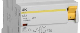
The RU-21 indicator relay in the U4 climatic version has been produced since the times of the USSR
The operator’s senses are not able to detect the fluctuations of the algorithms in the electrical circuit, which must be determined in order to make one or another operational decision. The reliability and uninterrupted power supply often depends on such decisions.
To detect deviations in the network, indicating relays are installed in the circuits, changing the initial state when a certain value changes in the device to be monitored. Such relays are called indicating (signal) relays; there is also a special designation - blinker.
Blinkers are able to indicate the operation taking place inside the controlled device. The contacts of such devices are used in communication and communication circuits with current limitation, the strength of which should not exceed 2A.
Indicating devices allow the operator or dispatcher to monitor the functioning of systems and their protective circuits and automatic devices by:
- indicators;
- audio signals;
- location of signs.
The element used to collect and supply data is an indicating relay. By means of it, the appearance of voltage or current is monitored at a specific interval of the circuit. After arriving at the insertion, the device is triggered, the contacts are moved to a certain position and a command is given to move the pointer.
The part will be located in this position until the operator inspects the relay and records the completed operation. The element then returns to its original position.
The indicator relay performs the following functions:
- switches on when switching to the winding circuit to be monitored by lifting the load or tensioning the return spring of the alarm element;
- triggers when any violations are detected in the system subject to control;
- returns to the normal operating position manually after the operator monitoring the system pays attention to the operation.
Explanation of the abbreviation of intermediate relays
To conveniently determine the functional purpose, number of contacts and other parameters, the relays have alphabetic and digital designations:
- P – intermediate;
- E – electromagnetic;
- 46 or (XX) – product series;
- 1 – pulse control signals.
Further designations may determine for what climatic conditions the product is adapted and the number of contact groups.
An example of how the symbols are deciphered
REP26-004A526042-40UHL4
- REP – electromagnetic intermediate relay
- Episode 26
- XXX – functional purpose and number of contacts
| appointment | Quantity | ||
| closing | opening | switching. | |
| 001 | — | — | + |
| 010 | — | + | — |
| 100 | + | — | — |
| 002 | — | — | ++ |
| 020 | — | ++ | — |
| 110 | + | + | — |
| 200 | ++ | — | — |
| 003 | — | — | +++ |
| 120 | + | ++ | — |
| 210 | ++ | + | — |
| 300 | +++ | — | — |
| 004 | — | — | ++++ |
| 220 | ++ | ++ | — |
| 310 | +++ | + | — |
| 400 | ++++ | — | — |
- 001 – means that the relay contains 1 switching contact, 010 – one breaking contact; 400 – four normally open contacts.
- A….D – wear resistance class of the materials from which the contacts are made;
- X – type of current in the winding of the electromagnetic coil, type of design for returning the mechanism to its original state,
1 – ~ current;
5 – direct current;
6 – direct current in the current coil;
- XX – two-digit digital code showing the design of mounting the relay housing on the surface and the method of connecting wires to the terminals:
| Code | connector | Wire connection method |
| 16 | —- | Solder |
| 18 | —- | "faston" |
| 76 | —- | seal |
| 21 | + | screw connections |
| 26 | + | solder |
| 78 | + | seal |
- XX – code indicating the magnitude, type of voltage, current in the coil winding
| Codes for electrical parameters of the closing coil | ||
| constant | ~ current 50 Hz | |
| 01…6 V 02…12 V 03…15 V 04…24 V 06…48 V 09…60 V 11…110 V 13…220V | 21…12 V 22…24 V 24…40 V 26…110 V 27…220 V 28…380 V 34…230 V 35…240 V | |
Codes from 01 to 13 indicate that the coils of these relays are DC with different voltages from 6 to 220V. Codes 21 to 35 indicate that the coils are rated for ~ I with U = 12…. 240 V frequency 50 Hz.
The last designation X indicates the presence of special elements in the design:
2 – manual relay switch;
5 – with manual manipulation and electronic relay position indicator for 24V products;
6 – with a manual manipulator and a diode to protect relays at 24V and less;
7 – the relay includes all three previously listed elements,
40 is the degree of protection from moisture and dust IP- 40...56..68;
UHL4 is a model for the corresponding climatic conditions, given for the north and middle latitudes. The letter “O” indicates that the product is adapted for the tropics.
REP26-004A526042-40UHL4 - this abbreviation indicates that the intermediate relay has 4 switching contacts with class A (wear resistance), direct current, contact connection with connectors, wires are secured by soldering, a 24 V coil, the design has a manual manipulator. Protection class IP – 40 for northern and middle latitudes.
Tip #1. Some people neglect the degree of protection of the product; relays have thin contacts and are sensitive to dust and humidity. Therefore, the degree of protection must be taken into account, especially in facilities with high humidity and dust. In explosive areas, it is recommended to use semiconductor products that do not spark during switching.
Despite the different designs and technical characteristics, all intermediate relays have basic common parameters by which compliance with the functional purpose is determined.
Types of time relays
Types of time relays by general design
So, we found out that switching contacts in a time relay occurs with a certain delay after the supply or control voltage is applied or removed. But before we move on to the consideration of the devices themselves that ensure operation according to a given algorithm, we note that time relays, according to their layout or general design, can be divided into several types.
- Monoblock time relays . These are completely independent devices with their own housing, built-in power supply or a device for connecting power, with an output to which you can connect third-party household or other equipment. Such a relay can be installed in almost any place as needed, and the device (system) that requires such time control can be connected to it. A classic example would be a time relay, with which those who have been involved in photo printing are very familiar.
Such a time relay made it possible to very accurately observe the selected exposure of photographic paper when printing photographs.
Devices of wider use include modern time relays (timers) that stop at a socket and have a socket for connecting a power plug to the load. The simplest example of use is that you can program in the evening so that water is boiled in the electric kettle before the owners get up in the morning.
Time relays (or timers) that are plugged into an outlet and themselves become a “controlled outlet” for the electrical appliance connected to them. As you can see, they can be electromechanical and electronic.
- Built-in time relays . They do not have their own housing, are one of the components of an electrical device (or are intended for such installation), and, as a rule, are not used autonomously. A classic example of such a time relay is a mechanical or electronic timer that controls the operating modes of a washing machine, microwave, electric oven, etc.
Built-in time relay, as a separate unit of the general device of a large household appliance.
Such relays can be electromechanical, having a block design. Another option is an electronic type relay assembled on a printed circuit board, which is connected to the general circuit of an electrical device.
Electronic time relay, made in the form of a mounting assembly on a printed circuit board
- Modular time relays . As is clear from the name, such devices have standardized dimensions and are intended for installation on the DIN rail of the distribution board. There, in the switchboard, a stationary connection is made to the power source and the load, the operation of which they will control. For example, in this way you can connect lighting systems that will operate according to a certain time algorithm, powerful heating devices, say, so that their main operation occurs during the hours of the discounted tariff, ventilation units to ensure a given ventilation frequency, etc. They can also be used with other large household appliances, if they do not have their own built-in timer in their design.
Modular time relays are available for sale in a wide variety of models of varying degrees of complexity and functional equipment
. Despite the uniformity of size, modular time relays can differ significantly in the range of capabilities, number of channels and programmable intervals. Depending on the degree of complexity and, partly, on the permissible power of the equipment connected to them, such relays can occupy one, two, three or even more module spaces on the DIN rail of the distribution board.
Such an electronic time relay with the ability to customize the daily cycle of operation will occupy three module spaces on the DIN rail
Convenient - such devices take up very little space, are not in plain sight, and are inaccessible to children. Many allow you to set a daily, weekly, monthly or even annual operating algorithm, that is, they do not require frequent intervention in management. But if there is a need to make adjustments, then the convenient location of the time relay on the rail, with all the controls located on the front panel, will allow this to be done without any difficulty.
Types of time relays according to operating principle
Now it’s worth figuring out what mechanisms provide the required time interval. According to this criterion, time relays can be divided into several types - these are electromagnetic devices, devices with a pneumatic or hydraulic retarder, motor ones, relays with a mechanical clock mechanism and electronic ones.
Prices for CRM time relays
CRM time relay
Let's look at them briefly in the order listed.
Electromagnetic time relays
They are usually used in start-up and stop stages of powerful equipment - they allow the start-up of individual components (mechanisms) to be spaced out somewhat in time in order to avoid sudden surges in the load on the power line.
The operating principle of the response delay unit is as follows. Structurally, the relay is an electromagnetic coil. The movement of the armature attracted to the core of the coil is transmitted to the contact closing/opening mechanism. But a sleeve (most often copper) is put on a common core with the coil, which becomes an additional short-circuited circuit.
The principle of an electromagnetic time relay
When supply voltage is applied to the coil, an EMF is induced in this additional “winding”, creating a current in such a direction that it is “opposite” to the current in the main coil. That is, it kind of “quenches” the rate of increase in the intensity of the electromagnetic field necessary to attract the relay armature. And as a result, the contact group does not operate instantly when the power is turned on, but with a delay, the duration of which can be adjusted by the level of compression of the armature spring. The delay range is typically between 0.07 and 0.15 seconds.
A “classic” example of an electromagnetic time relay is the REV 812 model used in power supply circuits of powerful equipment.
When the power is turned off, the opposite picture occurs - due to the presence of an additional winding-sleeve, a kind of “inertia” effect is observed, and the opening of the contacts also occurs with a delay. It can range from 0.5 to 1.5÷2 seconds.
Pneumatic or hydraulic time relays.
It is unlikely that you will have to deal with them in everyday conditions - they, too, were installed only on powerful processing equipment. But it will still be interesting to get acquainted with the deceleration mechanism, because it has a rather original design.
Time relay RVP 72-3221 with pneumatic retarder
Structurally, such relays necessarily include a chamber with a diaphragm, into which a movable unit (block) rests, causing switching of contacts. When the voltage is removed from the coil winding, the block is released and begins to move under the action of the spring. But the movement of the block is slowed down by the diaphragm until the air leaves the pneumatic chamber. And the speed of air release depends on the cross-section of the hole, which, in turn, is regulated by a special needle.
Adjustments to the response delay interval can be carried out over a fairly wide range and with a high degree of accuracy.
In addition to pneumatic ones, there are also hydraulic retarders, in which liquid (for example, transformer oil) is passed through an adjustable hole between the chambers. But the operating principle does not change.
Motor time relays
Such devices also seem to be becoming relics of the past, although they can still be found on older types of industrial equipment.
Operating principle of motor timing relay
A characteristic feature of such devices is the presence, in addition to the coil inherent in most relays, also of its own electric drive. When the power is turned on, it is supplied to both the coil and the electric motor, from which rotation is transmitted through a gear system to the impellers. On these wheels (which have a time graduation) there are special protrusions that at a certain moment will cause the contacts of the coil power circuit to close or open. Well, turning on or off the power on the coil winding, in turn, provides the necessary switching of the power lines connected to the time relay.
Prices for Feron time relays
Feron time relay
The response time is set by the initial position of the impeller. By the way, one relay can have several such wheels, which makes it possible to organize rather complex algorithms for controlling the connected load.
Motor time relay VS-33
Time relay with anchor (clock) mechanism
The simplest and most obvious example of an analogue of such time relays is an ordinary table clock with an alarm clock, powered by a battery. The response time is set by a separate special arrow. And when the hour hand aligns with it, the contact will close and power will be supplied to the sound signal generator.
Of course, the time relays themselves are somewhat more complicated, and the load connected to them is much more powerful than a miniature beeper. But the principle of operation is very similar. The timekeeping mechanism is almost completely analogous to a conventional watch. In some older relays, even the spring is wound manually, as needed. In others, the winding is carried out automatically when the power is turned on due to the movement of the electromagnetic armature.
Time relay with clock mechanism RV 235 UHL4. They have been discontinued for a long time, but continue to serve faithfully for some owners.
Relays with a clock mechanism are available for sale in a wide variety. Models with a dial divided into 24 hours are very popular among users, and each hour is usually divided into four segments of 15 minutes. Each such minimum interval corresponds to a movable sector (pin, lever, depending on the model).
When the relay is connected to the network, the dial begins to rotate at an angular speed of one revolution per day. The dial displays the current astronomical time. Well, then it’s easy to program the relay operation algorithm by pressing (tilting or otherwise moving) the movable sectors corresponding to those periods of time when the power to the load should be turned on.
Programming the operation algorithm of such a time relay is simple and intuitive.
Such time relays are available in a modular or monoblock design, that is, they are either installed in a distribution cabinet or directly connected to an outlet. Their low cost and ease of operation have earned them wide popularity. The accuracy of setting the range and relay operation, of course, cannot be called high (minimum gradation of 15 minutes), but for most household appliances this is quite enough.
Well, if more precise settings are required, down to the second gradation, then it is best to immediately purchase an electronic time relay.
Learn how to wire an outlet and see step-by-step examples of how to properly connect a wire to an outlet.
Electronic time relays
Electronic time relays are currently increasingly replacing their electromechanical “brothers”. This is understandable - what attracts is the high accuracy of operation, the possibility of programming for a long period: for a week, a month or even more, taking into account the alternation of weekends and holidays, season changes, and other factors influencing the expected operating mode of electrical appliances connected to the relay.
Electronic time relay with a rich set of programming capabilities for the control algorithm of connected electrical devices or systems
This category also has its own division for response timing technology. We will not delve into the topic - this question is rather of interest to electronics specialists.
We can only briefly explain that the simplest electronic relays count time using RC circuits (resistor + capacitor). The charging time of the capacitor depends on the value of the capacitor itself and the resistor connected to it in the circuit. That is, it is easy to calculate, and by smoothly changing the values of circuit elements or changing chains (in some relays there are several of them), you can set the desired response delay interval.
More complex time relays are equipped with special microcircuits or a cascade of semiconductor devices that provide the necessary time delay. Well, the most modern ones today have microprocessor units and quartz reference frequency oscillators. So the time counting in them occurs with maximum accuracy, and the non-volatile memory allows programming of the operating algorithm.
Electronic time relay of modular design with analog adjustment of operating parameters. Relatively inexpensive and very often - quite enough.
The range of electronic time relays is very wide. It is quite possible to purchase a relatively inexpensive model with analog parameter settings and providing the simplest operations of turning on and off the power line with the required delay or according to a certain algorithm. Often, to implement the intended automation of a particular process, such a device is quite sufficient. More advanced time relays are equipped with digital liquid crystal displays and a push-button (touch) control system with parameter setting accuracy literally down to a fraction of a second. Convenient, but the cost certainly increases proportionally.
You can also add that electronic time relays can be produced in any of the designs - as separate monoblock devices (for example, again, the “socket with timer” option), in the form of boards or blocks for installation in equipment, or in a modular layout for placement on DIN rail.
Video: Example of using an electronic time relay KEMOT URZ2001-1
* * * * * * *
By the way, there is a lot of confusion about what is more correct to call such devices - time relays or timers. Arguments are given that the operation of the relay is linked to astronomical time, and the timer only counts down a given interval. Or vice versa, that the relay should only provide a delay on and off, and all that concerns programming capabilities (setting the operating algorithm) are timers. Thus, the statements directly contradict each other.
According to the author of this article, the “border” between these types of devices, if there is one, is very arbitrary. And fooling yourself with the subtleties of terminology hardly makes sense in this case. The main thing is to understand and be able to formulate why you need a control device and what functions it should have. And you can rest assured that a competent sales consultant will understand you perfectly and offer the optimal model. And by the way, her passport may indicate both a timer and a time relay. And often – both terms at once, separated by a dash or in parentheses.
Main technical parameters of intermediate relays
All relays, including intermediate ones, are evaluated according to the following parameters:
- Switched voltage value;
- Rated current value at switching contacts;
- Minimum switching current;
- Permissible short-term current through switching contacts;
- Interval of voltage value on the electromagnet coil;
- Power consumption of the switching coil;
- Closing time;
- Contact opening time;
- The wear resistance of contacts is assessed by the number of relay activations;
- The maximum permissible load power, which is connected through the relay contacts.
These are general parameters of technical characteristics; depending on the design and purpose, there may be additional ones. Let's look at specific technical characteristics using the example of REP - 26 different modifications.
| options | magnitude |
| Switching voltage range | AC 5–381 V DC 5–221 V |
| Rated current on contacts | 10.1 A9.1 A8.1 A6A |
| Minimum contact current | 0.06 A0.01A |
| Through current on contacts (A) | 161A |
| Interval of voltage changes in the control circuit | +5,1 %-15,1% |
| power consumption by the coil - at DC. current with 1-3 contacts - at DC. current with 4 contacts - with alternating current | 1.6 kV2.1 kV3.1 kA |
| Response time, no more. | 0.03 sec |
| Release time, no more. | 0.03 sec |
| Mechanical wear resistance. | 30 million triggers |
| Switching power - with alternating current - with direct current | 1.6kW3kW150W250W |
Connecting an intermediate relay to circuits with loads for various purposes
Most intermediate relay models are adapted to standard mounting conditions, on a flat surface or on a DIN rail in a distribution cabinet. After installation, the relay can be connected to the electrical circuit of the system:
- First of all, the functionality of the relay is checked by connecting the coil contacts (13 and 14) to the power source, and a characteristic click of contact switching is heard.
This contactor diagram shows the position when there is no power to the coil.
When a voltage of 220, 24 or 12V is applied, contacts 9 – 10 – 11 – 12 are closed to the corresponding pairs 5 – 6 – 7 – 8.
In this connection diagram, the relay plays the role of a contactor distributing power to the load elements.
- The neutral wire is directly connected to one of the coil contacts;
- The phase is connected through a normally closed “Stop” button, which opens the circuit;
- Sequentially with the “Stop” button, the start button is turned on, which is open in the normal state and works to close the circuit;
- The second contact of the start button is connected to the phase;
- The phases are connected to normally open contacts;
- Load to normally closed contacts;
- One of the output contacts to the load is connected between the start and stop buttons; after starting, the circuit will provide a constant supply of voltage to the coil, the contacts will be closed. The relay and load will be disconnected when the circuit is broken by the “Stop” button.
The load can be a variety of electromechanical elements; to connect a high-power load, intermediate relays control the operation of a magnetic starter with contacts capable of passing large currents. Intermediate relays can be controlled by light sensors, a thermostat or a motion sensor, depending on the functional purpose of the circuit.
Control circuit for an electric heating system via a thermostat and a magnetic starter
The operating principle of this scheme is similar to the previous one. Only the start is carried out automatically by a thermostat, power is supplied to the coil of the magnetic starter, after which the heating elements are connected.
Simple automation: Easy programmable relays
Hello, dear community! On Habré, a lot of words have already been said about various automation devices, ranging from simple Arduino to industrial multiprocessor systems. I want to fill in another blank spot on the Habro-Automation map with an article about intermediate devices - programmable relays
, using the example of Easy microprocessor devices manufactured by Eaton (Moeller) Corporation. Quite a lot of time has passed since my first acquaintance with this type of device, but as before, these “electronic babies” remain indispensable assistants for implementing a wide range of engineering and household tasks.
Programmable (smart) relay
is a type of programmable logic controllers (PLC). Programmable relays have found their main application as automation tools for local circuits, individual units of machines and mechanisms, and for domestic use. Based on intelligent relays, various automatic control systems are built intuitively and clearly, for example, control systems for pumping equipment, drilling machines, and automatic transfer transfer systems (ATS). Compact dimensions and ease of programming make it possible to develop smart home system elements based on programmable relays. Standard means of describing and constructing programs for these devices are relay logic languages () or function block languages (FBD), developed specifically for engineers involved in the field of industrial and production automation. The simplicity of the programming language and the ease of transition from obsolete automation systems based on relay-contactor circuits to microprocessor devices have allowed programmable relays to take a reliable position in the automation device market.
Theory
Relay as the main programming operator
Based on the name of the described class of devices, the main operated element will be a relay. A relay
is an electromechanical device designed to switch electrical circuits for given changes in electrical or non-electrical input quantities.
A classic relay has a control coil x
and a group of contacts that implement the output function
y=f(x)
. When a control voltage is applied to the coil input, the contacts change their initial state to inverse.
A contact group can contain two main types of contacts: normally open contacts
and
normally closed contacts
. Normally open contact - a contact that is in an open state when there is no voltage on the control coil. Normally closed contact - a contact that is in a closed state when there is no voltage on the control coil.
Thus, we can write two main types of functions implemented using relays: y(x) = x
— for normally open contacts;
y(x) = x̅
- for normally closed contacts.
Other types of functions implemented using relays are based on giving the contact group additional properties. The functions and types of relay contacts are shown in the figure below.
1 - relay coil (control circuit), 2 - normally open contact, 3 - normally closed contact, 4 - normally open contact with retarder when activated, 5 - normally open contact with retarder when returning, 6 - normally open pulse contact, 7 - normally open contact without self-resetting, 8 - normally closed contact without self-resetting, 9 - normally closed contact with retarder when activated, 10 - normally closed contact with retarder when returning.
Elements of the theory of discrete automated devices
A discrete automated device
as a control device that processes a priori and current information into control information, and the carriers of all of the listed components of information are signals that are discrete in level and time.
This means that the signal state of each input (output) of an automated device is characterized by two levels: the minimum, conventionally designated “0,” and the maximum, designated “1.” Drawing up a block diagram of control according to the given conditions of its operation is called synthesis
. Determining the operating conditions of a circuit or its individual elements based on the existing structure is called analysis of control circuits.
Circuits based on relay and contactless elements can be composed in two ways.
First way
experienced, widely used in the practice of logical design of relay-contactor circuits. Based on the given operating conditions of individual parts of the working machine, a schematic diagram of the automation system is drawn up. Similarly, non-contact analogues of relay-contact circuits are constructed, in which the specified operating conditions of the circuit are expressed in the form of functions of logic algebra. In this case, it is advisable to minimize any contact or non-contact circuit built in such an experimental way. Minimization of circuits is carried out based on the laws of logical algebra.
Second way
The construction (synthesis) of circuits is based on a more complete use of the theory of algebra of logic and the principles of formalizing the real operating conditions of an automation circuit. In this case, they proceed from the given operating conditions, compiling the corresponding state tables (function maps), where they mark combinations of arguments and function values (output signals) in the form of logical “1” and “0”. The main task of synthesis is to determine such a form of expression for the desired logical function that can be implemented using the minimum number of elements as simple as possible. The synthesis of relay control circuits comes down to drawing up a structural formula (analytical expression) describing the logical functions that must be performed by a given device. Then the resulting algebraic formula is analyzed and a graphical outline of the diagram is drawn up.
Analysis of the full course on the theory of logic and circuit synthesis is beyond the scope of this article; anyone interested in this topic can familiarize themselves with the subject in detail using references to the literature (at the end of the article).
Let's look at the process of creating a control scheme using a simple real-life example.
Synthesis of a relay contactor control circuit using an example
Formulation of the problem
It is necessary to develop a lighting control system for office premises in accordance with the following conditions:
Given
Office space with one group of main lighting (fluorescent lamps) and one group of duty and background lighting. Electric blinds.
Necessary
- At the end of the working day (18:15), ensure that the main lighting group is turned off and the emergency lighting is turned on. If the blinds remain closed, ensure they open.
- Before the start of the working day (8:45) ensure that the emergency lighting is turned off.
- If there is insufficient natural light, ensure that the main lighting is turned on based on a signal from the dimming sensor, provided that the blinds are open.
- Ensure that background lighting is turned on when the blinds are closed. If the main lighting was on, turn it off.
- When the background lighting is turned on, provide for automatic lowering of the blinds.
Additional terms
- The light sensor has a binary output that is adjusted to a certain light threshold. When there is insufficient light, the contact closes.
- The blind drive system has contacts that inform about limit positions.
Solution
Let's first determine the correspondence of the input and output signals of the system being designed to variables. Let us agree to denote all input signals by variables I
, respectively.
index, and all output signals are Q
with the corresponding index.
Input Variables
: I1 - light sensor signal. I2 - signal for the upper position of the blinds. I3 - lower position signal for blinds. I4 - signal to turn on the background lighting.
Output Variables
: Q1 - turn on/off the main lighting group. Q2 - turn on/off emergency lighting. Q3 - turn on/off background lighting. Q4 - raising the blinds. Q5 - lowering the blinds.
Time Variables
: T1 - reaching the end of the working day. T2 - reaching the start time of the working day.
Next, we will divide our problem into conditional parts and compose logical functions for each of the parts.
- End of the working day Turn off the main light: Q1=not(T1)
- Turn on the emergency light: Q2=T1
- Open the blinds if they are closed: Q4=not(I2)⋅T1
- Turn off the emergency light: Q2=not(T2)
- Turning on the main light by light sensor, checking whether the blinds are open: Q1=I1⋅I2⋅not(T1)⋅T2
- Switching on background lighting with closed blinds: Q3=I3
- When the background lighting is turned on, lower the blinds unless it is the end of the working day: Q5=I4⋅not(I3) ⋅not(T1)⋅T2
So, we have obtained logical functions that describe the behavior of the elements of our system depending on conditions and disturbing influences.
Next, it is necessary to make the transition to a relay-contactor circuit, i.e., to describe the operation of our system on real physical devices. The transition from logic algebra functions to a relay circuit is very simple. To do this, it is enough to represent all the input and intermediate variables in the form of relay contacts, and the output functions in the form of relay coils. A special word needs to be said about time-dependent variables. In our example, these are variables describing the time period of the working day, T1 and T2. To represent time-dependent variables, there are special types of relays - time relays and timers.
Iron
To move on to the practical part of our task, we need to figure out on which hardware it is more profitable and convenient to carry out the given solution. Manufacturers present a fairly wide range of programmable relays for optimal cost and functionality solutions to certain types of engineering problems. Let's try to understand this diversity. A programmable relay is usually a monoblock design that has power connection terminals, inputs, outputs, a liquid crystal screen and controls.
At the top of the device are located:
- terminals for power connection;
- device digital input terminals;
- analog input terminals (0..10 V).
At the bottom of the device are located:
- terminals of the relay (or transistor) outputs of the device.
On the front panel there are:
- LCD screen - for displaying information messages, editing a program, changing parameters;
- keyboard - to navigate through the device menu;
- connector for connecting the programming cable.
Powering devices
Based on voltage and type of power supply, programmable relays are divided into:
- devices with power supply 12, 24 V (DC);
- devices with power supply 24, 110-220 V (AC).
Digital inputs
The power supply and type of supply voltage of the programmable relays determine the value of logical one at the digital inputs of the device. That is, in order to apply a logical one to the input of the device, it is necessary to apply a voltage corresponding in its value and type to the supply voltage of the device. Thus, according to the input voltage there are:
- devices with 12, 24 V (DC) inputs;
- devices with inputs 24, 110-220 V (AC).
Depending on the type of Easy programmable relay, one or more digital inputs can be used as “fast counters” - to count pulses with a frequency of up to 3 kHz.
Analog inputs
To process analog signals, such as signals from temperature sensors, wind speed sensors, external potentiometers, Easy programmable relays have two or more analog inputs 0..10 V (DC) on board. It should be noted that analog inputs are provided only on devices with 12 V (DC), 24 V (AC, DC) power supply.
Relay and transistor outputs
To switch output signals, Easy programmable relays provide 4 or more outputs. Device outputs are of two types:
- transistor outputs providing the ability to switch small loads up to 0.5 A;
- relay outputs providing switching of loads up to 8 A (AC1).
Devices with transistor outputs are primarily used where switching with low currents is required, or where the task is to transmit signals from the output functions of the relay to other parts of the automation system. Devices with relay outputs can be directly connected to lighting sources, low-power motors and other consumers with an active load not exceeding 8 A.
Analogue outputs
Programmable relays of the Easy800
have an analog output (0..10 V) on board.
Screen
The built-in screen is designed to display text (in devices of the Easy500, 700, 800 series) and graphic (in devices of the MFD-Titan series) information.
Communications and system scalability
Ethernet
– connectivity via an expansion module that implements the functions of an OPC server. For the entire line of devices.
Profibus, CANopen, DeviceNet, As-i
– possibility of connection via expansion modules. For devices of the Easy700, Easy800 series.
Easy-net
– the ability to connect programmable relays to a network. For Easy800, MFD-Titan devices.
Expansion modules are available for devices of the Easy700, Easy800 series, allowing you to increase the number of inputs and outputs of the devices. Expansion modules can be end-to-end mounted using an adapter, or installed remotely (up to 100 m). Remote installation is convenient if, for example, you are implementing a control system for two rooms.
Only one expansion module can be connected to one Easy programmable relay. Programmable relays of the Easy800 series have an Easy-net interface on board, which allows you to combine up to 8 devices into a single network, and an expansion module can be connected to each of the devices. In this way, it is possible to organize a system with up to 328 inputs/outputs.
Easy programmable relay range
Easy programmable relays are represented by devices of the Easy500, Easy700, Easy800 and MFD-Titan series.
Easy500 series programmable relays
An initial series of programmable relays designed to solve simple automation tasks, such as: control of small room lighting, heating systems, presence control, motor start control, compressor or pump control.
Main characteristics of Easy500 series programmable relays
- Supply voltage and digital input voltage: 24 V and 100 – 240 V AC, 12 V and 24 V DC.
- 8 digital inputs.
- 2 analog inputs: 0 - 10 V (0 - 1023 bit), in versions with power supply 12 V, 24 V DC and 24 V AC.
- 4 relay outputs: 8 A, or 4 transistor outputs: 24 V DC/0.5 A.
- 128 “program lines” with 3 contacts and 1 coil.
- Easy500 series relays do not have the ability to connect expansion modules.
Easy700 series programmable relays
Devices that combine all the advantages of Easy500 series devices, with the ability to connect additional expansion units: analog and digital inputs/outputs, communication modules, etc. This series of Easy programmable relays is optimal for solving fairly complex automation problems, with the ability to control a large number of signals (lines). Also, the devices are ideal for use in projects that require further expansion of the control system capabilities at minimal cost.
Main characteristics of Easy700 series programmable relays
- Supply voltage and digital input voltage: 24 V and 100 – 240 V AC, 12 V and 24 V DC.
- 12 digital inputs.
- 4 analog inputs: 0 - 10 V (0 - 1023 bit), in versions with power supply 12 V, 24 V DC and 24 V AC.
- 6 relay outputs: 8 A, or 8 transistor outputs: 24 V DC/0.5 A.
- 128 “program lines” with 3 contacts and 1 coil.
- Possibility of connecting expansion units.
Easy800 series programmable relays
An advanced and most functional series of Easy devices, allowing for a flexible solution to almost any task in household and industrial automation.
Easy800 series devices can be expanded with additional functionality and communication modules. In addition to the standard features found in easy500/700, such as multifunction relays, impulse relays, counters, analogue comparators, timers, real-time clocks and non-volatile memory, easy800 additionally contains PID controllers, arithmetic blocks, value scaling blocks and many other functions . Also, the ability to network up to 8 devices makes the easy800 the most powerful programmable relay on the electrical market. When solving complex problems, Easy800 programmable relays can be combined into one common network of EasyNet devices. Main characteristics of Easy800 series programmable relays:
- Supply voltage and digital input voltage: 24 V and 100 – 240 V AC, 12 V and 24 V DC.
- 12 digital inputs.
- 4 analog inputs: 0 - 10 V (0 - 1023 bit), in versions with power supply 12 V, 24 V DC and 24 V AC.
- 6 relay outputs: 8 A, or 8 transistor outputs: 24 V DC/0.5 A.
- 256 “program lines” with 4 contacts and 1 coil.
- Integrated EasyNet interface for connecting devices into a network (up to 8 devices).
- Possibility of connecting expansion units.
Practice
Device selection
And so, we have examined almost the entire line of devices, we know their main characteristics. All that remains is to select the necessary programmable relay to solve our problem. Since our task is quite trivial and does not require additional communication and other device capabilities, we will use a simple algorithm to select a suitable Easy programmable relay.
- Let's determine the number of digital inputs
. We have 4 input variables I1..I4, so it is enough to have 4 inputs in the device. - Let's determine the supply voltage and type of digital inputs
. Since we plan to use a programmable relay for domestic needs, with a 220 V, 50 Hz intra-house power supply, the most suitable device will have similar power requirements and digital input voltage values - 220 V, 50 Hz. - Let's determine the types and number of output contacts
. To control 5 output variables, we need to select a device with the appropriate number of outputs. Since the outputs of a programmable relay must provide switching of intra-office light sources and other power devices, then we need the presence of relay outputs.
Using the catalog of programmable relays, we select the type of device that is most suitable for our purposes: EASY719-AC-RC10
. The selected relay has on board:
- 12 digital inputs (220 V, 50 Hz);
- 6 relay outputs (load switching up to 8 A);
- real time clock;
- device power supply – 110-220 V, 50 Hz.
Development environment
To develop automation systems based on Easy programmable relays, the device manufacturer offers a fairly convenient and practical development environment Easy-Soft
. The software makes it easy to “draw” your relay circuit using a convenient graphical development environment. If necessary, it is possible to select one of several types of display of relay contactor diagrams:
- Contacts and coils are displayed in accordance with IEC standards;
- contacts and coils are displayed in accordance with GOST standards;
- Contacts and coils are displayed according to ANSI standard.
Easy-Soft has an emulator that allows you to debug the program without connecting a physical device. Software documentation is available in several languages, including Russian. You can download the demo version of Easy-Soft from the link.
Programming
The process of writing a program for a programmable relay Easy comes down to “drawing” a relay-contactor connection diagram in accordance with the obtained logical functions and determining the necessary parameters, such as time constants, timer values, etc. Let's launch Easy-Soft and create a new project. Select the required device type from the list on the left and drag it into the project window. A menu for selecting the device version will appear. From the drop-down list, select version 10-хххххххх - this corresponds to devices that support the Cyrillic alphabet.
Next, go to the section for editing the wiring diagram
by selecting the appropriate item in the menu at the bottom left. Configure the connection diagram display option that is convenient for you using the appropriate menu. For me, the first display option is more convenient, as it allows you to view the program in its usual form - from top to bottom. For electrical engineers, perhaps the second option will be more convenient, since it corresponds as closely as possible to standard relay contactor circuits.
Let's move from the logical functions of the lighting control system that we synthesized in the “theory” section to the relay contactor circuit. To do this, it is enough to represent all the input and intermediate variables in the form of relay contacts, and the output functions in the form of relay coils. Since one line of program can only contain 3 contacts and one coil, intermediate variables should be introduced if necessary to break up long logic functions. Intermediate variables are called markers
in the ideology of relay contactor circuits.
To determine the end and beginning of the working day, it is convenient to use a weekly timer
(H), which has flexible settings for days of the week. Also, using a weekly timer allows you to use only one variable to determine the boundaries of the working day.
To “render” a relay circuit, simply drag the necessary elements from the menu on the left onto the project workspace. The elements are connected using the pencil tool. After adding elements to the diagram, you need to determine their available parameters. Let's see how to do this using a weekly timer as an example.
The weekly timer is designed to initiate any actions during the week, depending on the established time limits. The timer has 4 independent channels A, B, C, D. Each of the channels can be configured for specific time periods. For example, in our case, the configuration of the weekly timer ensures that it operates from Monday to Sunday, from 18:45 to 8:45.
You will be correct if you notice that our example uses an office space whose working days are usually from Monday to Friday.
The final relay-contactor circuit of our example
Debugging
After constructing the relay contactor circuit, it is convenient to use the program debugging mode. To do this, just go to the Simulation
. All input and output signals of the device, as well as all variables of the programmable relay, are available for simulation. For ease of debugging, it is possible to configure the type of input signals. For example, by simulating the position of blinds, it is convenient to configure the corresponding input signal as a self-locking button. This will allow you to click on it once and fix its position. When using debug mode, the current time of the simulated device is your computer's system time.
Firmware
If you have a real physical device, after debugging the operation of the relay contactor circuit, you need to flash it into a programmable relay. To do this, use the menu item Communication
. I think there is no need to comment on individual menu items, since they are intuitive.
Connecting and assembling the control system
When implementing real tasks, the next step would be the physical connection of the programmable relay to the executive bodies and mechanisms, in our case, connection to the intra-office network.
It is fair to say that, as with any development from scratch, it is advisable to first debug systems built on programmable relays in the form of a prototype assembly. This is quite simple, taking into account the features of the device and the ease of connecting management and executive bodies.
When designing real control systems, you should be guided by the general rules for connecting programmable relays. You can find detailed information about connections in the device documentation (at the end of the article).
The main requirement when connecting a load (incandescent lamps, engines, etc.) is not to exceed the permissible currents at the group of device output contacts:
- 8 A resistive load (AC1) for devices with relay outputs;
- 0.5 A - for devices with transistor outputs.
If the permissible loads are exceeded, for example when controlling an electric heated floor, intermediate contactors
. In this case, the load will be limited only by the power of the intermediate contactor.
Conclusion
I hope that many who did not know about the described class of devices now have the information and initial knowledge to begin implementing their ideas that may have arisen while reading this article.
I would like to believe that my work was not in vain and the information presented will be useful to people for the practical implementation of their engineering ideas in industry and at home. With Easy programmable relays it's really simple and fun!
If the Habrocommunity finds the information interesting, I plan to prepare a number of articles for the future on the practical application of the described devices in automation and industry. I’ll tell you about some undocumented capabilities of Easy programmable relays, for example, how to make a graphical interface with the ability to monitor all internal variables. Yes, you are absolutely right, you can build a dispatch system with a graphical interface using the Easy relay.
Helpful information
[1] Wikipedia – algebra of logic.
[2] Wikipedia – Karnaugh maps – methods for minimizing Boolean functions. [3] Wikipedia – relay. [4] Documentation for programmable relays of the Easy500, Easy700 series. [5] Documentation for Easy800 series programmable relays. [6] Easy Relay Training Center - many examples of the use of Easy programmable relays (in Russian). [7] Software for Easy relays (including in Russian). [8] Manufacturer's website. [9] Catalog of programmable relays Easy. [10] Easy - it's simple. Tutorial. O.A. Andryushchenko, V.A. Vodichev. Some links to documentation are provided not from the manufacturer’s website, but from the website of my company, since after the merger of Eaton and Moeller corporations, internal resources are being reconstructed, and links to documentation are sometimes unavailable.
UPD 1. Added literature [10] - a textbook for university students. Examples, laboratory work. UPD 2. Yes, these devices can be programmed directly from the built-in keyboard. Large programs, of course, are not very convenient to type, but for quickly editing circuits, it is quite possible to use this opportunity. UPD 3. Habrouser ShadowHacker suggests that it is more correct in terms of electrical engineering/electronics to use the expression “normally open contact” and “normally closed contact”. In the article I will leave the original terminology due to the fact that in Russian documentation and catalogs the terms “normally closed contact” and “normally open contact” are used for the device.
Consumer demand for relays from various manufacturers
There are a large number of relay manufacturers; among domestic ones, the products of FSUE NPP START in Veliky Novgorod, relay REP-26 004, REP-26 002, REP-26 003, are often used.
RP-21M, RP-21MN are produced at the Moscow and Cheboksary LLC "PKF Experimental Power Equipment Plant" in Cheboksary. These products are in good demand and are even counterfeited by Chinese competitors.
Tip No. 2 When installing Chinese models, be sure to test the contacts with a multimeter or other devices, in the initial state and after the relay is activated. It happens that the contacts stick, do not close or do not open.
On the right side is a variant of a Chinese fake.
Professionals recommend using imported models from manufacturers
ABB, Schneider Finder, Siemens, Electric, Relpol.
The wear resistance of the contacts of these products is much higher; failures in the control system of complex equipment can lead to production stops and costly repairs. Therefore, it is more rational to use more expensive but reliable relays.
Errors during installation and operation
- One of the common mistakes is the incorrect choice of technical parameters of intermediate relays. Look carefully in which networks the relay is used, direct or alternating current, what voltage or current needs to be supplied to the control coil.
- Be sure to take into account the permissible current loads on the switching contacts, especially when the relay is connected directly to power high-power devices.
- Try to use a relay with the required number of contacts; models with a larger number consume more electricity on the electromagnetic coil.
FAQ
- Is it possible to install a relay to control street lighting so that the motion sensor turns on one group of lighting fixtures and turns off the other?
One of the circuit options using a motion sensor
Of course it is possible, a detailed description of such a circuit requires a detailed consideration, but one thing is for sure, you will need to use a relay with a group of contacts for switching.
- Is it possible to use a relay with a large number of contacts to switch multiple loads without a magnetic starter?
A magnetic starter is definitely present in an electromagnetic relay, unless you use an additional starter with high-power contacts, which is controlled by an intermediate relay. This is possible provided that the relay contacts can withstand the load current for a long time.
One-button power management scheme | Master Vintik. Everything with your own hands!
Why such a strange scheme
Why is such a strange circuit for connecting a bipolar transistor given as an example?
Indeed, in this case, if there is no control signal, the transistor is closed by default and the load is energized by default! In order to avoid this, you will have to additionally install a pull-up on the base of the transistor, and only then, when the voltage is turned on, the load will not be automatically connected.
What kind of lighting do you prefer?
Built-in Chandelier
In addition, you will have to take into account the load current and choose a resistance of suitable power, and powerful resistors are never small. And it’s a bit difficult to install a radiator on them, unlike transistors.
And finally, the resistor gives a voltage drop, i.e. We will have to take into account that we will use less voltage for the load than the power supply provides.
In addition to the above, the advantages of bipolar transistors and the disadvantages of field-effect transistors are not listed. From the text at the moment it follows that field-effect transistors are definitely better, and for some reason they use bipolar ones, but why is unclear, because there are field-effect transistors, without any drawbacks.
First video version
In order to prevent accidental switching on or off, a delay when pressing is more often used. This can also be easily implemented in this circuit; the code below has been slightly modified and now switching on and off occurs with a three-second delay:
dim
flag
as Byte
'variable for executing the main program
dim
a
as Byte
'for organizing the delay
config
PORTB .
0 = OUTPUT
'LED output led
alias
portb . 0
config
portd.
3 = OUTPUT
'power management pwr
alias
portd . 3
config
INT0 =
low
level 'on/off button
On
Int0 Zapusk :
enable
int0 'enable interrupts
enable interrupts
if
flag = 1
then
'execute main program'….
'…. end if
if
a = 3
then
'if 3 seconds have passed
toggle
pwr 'toggle on/off
toggle
led
goto
ext 'exit loop
end if
loop
until
pind .
2 = 1 'while the button is pressed, spin here ext : a = 0 waitms
100 Gifr = 64
Expert opinion
It-Technology, Electrical power and electronics specialist
Ask questions to the “Specialist for modernization of energy generation systems”
Timer for radio Teaching you how to use EAGLE in this topic is not part of my plans. At the end of the article there is a link to a wonderful and very easy to learn tutorial on using EAGLE, I will just tell you some of my tricks when creating a board. Ask, I'm in touch!