Introduction
The history of research and discovery in the field of electricity is closely connected with the use of various designs of electrical machines to produce electrical charges, also called electrostatic machines.
The design of electrostatic machines is based on the principle of obtaining electrical energy through mechanical work expended when setting in motion (rotation) the moving parts of the machine, primarily to overcome the forces of attraction or repulsion acting at each moment between oppositely and similarly electrified moving parts of the machine. The study of the principles of operation of electrostatic machines, divided into friction machines and electrophore machines, contributed to a better understanding of the nature of electricity, so they were not only devices for producing large electrical charges, but also research benches.
Unlike friction machines, the action of electrophore machines is based on the excitation of electricity due to the phenomenon of induction, i.e. without direct contact of machine parts that cause electrification.
In this course work, using an electrophore machine, I will demonstrate the study of the fundamentals of electrodynamics and electrostatics, the nature of charge distribution on the surface of a conductor, and the introduction of the concept of “electrical capacity” using an electrophore machine.
§4 Making an electrophore machine at home.
To make an electrophore machine I needed the following materials:
— CD discs, two pieces; - aluminum tape; - a plastic card; — computer coolers, two pieces; — chipboard; - plexiglass; - aluminum wire, diameter 4 mm, 2 mm; — copper wire 0.5 mm and 2 mm; - Double-sided tape; - Leyden jars or non-polar capacitors; - notebook sheet; — contacts for fastening wires; — L-shaped (2 pcs) racks (corners); — rubber feet;
- adapter;
- electrical tape;
- self-tapping screws; — bolts with nuts;
- thin sheet metal;
Electric charge units
— terminal connections;
— fasteners for electrical wires.
The first part is the disks on which a static charge will form. To do this, I'll take 2 CDs.
First of all, we remove the coating from it.
Next I glue aluminum petals onto it. I need 80 petals for two disks.
I cut them out of aluminum tape and glue the petals evenly.
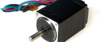
The second part is an electric drive, I make it from a computer cooler.
I disconnect the yellow wire from the cooler; it won’t be needed in the future.
Next you need to cut off the stiffening ribs, i.e. I disconnect the motor from the cooler body.
Question 7. What do you know about the Leyden jar
Now I tear off all the blades from the motor; they are not needed (Figure 13).
Next, I will mount the cooler on a cut piece of plexiglass, in which I will also drill holes.
I glue the motor to the plexiglass (hereinafter referred to as the strip).
I do the same operations for the second cooler.
I make capacitors from cans
I cover the inside and outside of the jar with aluminum tape.
The base of the electrophore machine was made from chipboard.
I fix L-shaped corners on a wooden base, opposite each other.
All machine components are ready, I’m moving on to assembly.
The work of the electric field when moving a charge. operating principle
Using double-sided tape, I glue the rubber feet to the wooden base at the corners.
I screw a bar with a motor onto the corners.
I glue the discs onto the motor using tape.
Right in the center.
We do the same with the second motor.
I will dwell in more detail on the contacts and frames; I make them from aluminum wire. All 2 parts.
We bend the wire in two places. At the ends in these places I drill holes for making contacts. Contacts are made of thin copper wire at the ends. Using contacts, we will remove electric current and voltage from the disks.
The second frame is in the form of an incomplete letter “P”. I also make contacts from wire, which are attached to drilled holes.
The electrodes were made from wire, with curved handles wrapped in electrical tape at the end. For fastening I use clamp connections.
Installation of parts.
I screw the Z-frame to the bar and press it against the disk with the contacts.
I mount the P-shaped frame, attach it to the capacitor from the can, and connect it to the electrodes. The electrodes can move relative to each other.
Now we check our prefabricated elements and tighten them so that nothing dangles.
We connect the wires of the electric motors and screw them to the adapter wires.
Electrophoric machine - electrostatic generator for experiments and physics classes PEG-20
We are pleased to present to the attention of young technicians and physicists, as well as physics teachers, an electrophoric machine - an electrostatic generator for experiments and physics classes PEG-20. This device is a static charge generator consisting of two wheels rotating in mutually opposite directions. Nowadays, this device is very often used by teachers in physics lessons to demonstrate the power of an electric arc. This device is a modern version of the Wimshurst generator and is an induction electrostatic machine. In it, a static charge is formed not through triboelectricity when friction is present, but through the induction of charges. The device is made of plastic and metal elements and has dimensions of 24 x 28.5 x 20 cm. The principle of use is very simple, just start twisting the appropriate handle and the device starts working. When the handle is rotated, the discs begin to move in opposite directions. The brushes begin to come into contact first with one and then with subsequent metal strips. With each revolution, more and more charge begins to accumulate, which ensures an increase in the potential at the contacts. As soon as the accumulated charge reaches its maximum value, further charge growth stops. For better accumulation, capacitors in the form of Leyden jars are used. After the charge has accumulated, bringing the contacts close enough to each other, a “discharge” occurs, which is clearly visible, after which the charge continues to grow again.
In everyday life, in this form, this device is not used, but serves only as a historical exhibit, illustrating the history of the emergence and development of scientific and technological progress and engineering. Laboratory demonstration shows various phenomena and effects of electricity. If you are a physics teacher or the director of an educational institution where students are clearly shown certain physical phenomena, then this electrophoric machine - an electrostatic generator for experiments and physics classes PEG-20 will become simply an indispensable tool for you in the field of getting to know electricity.
Precautionary measures:
Keep children away from the machine and do not allow children to play with this generator. Use this generator only if you are familiar with its capabilities and safety precautions. Since the machine generates high voltage, do not touch any metal parts while operating the machine. Remember to discharge the electrodes with the metal "Y" handle after completing the experiment. Do not turn the handle too much as the pulley system may be damaged. If a spark is not visible or heard, check the machine for moisture in the brushes. You can dry the car by holding it in the sun or next to a heating device (until the moisture is removed).. Specification:
Specification:
- Can be used to demonstrate experiments in physics classes
- Material: metal, plastic
- Size: 24 x 28.5 x 20 cm
- Weight: 1.4 kg.
Equipment:
Electrophoric machine - electrostatic generator for experiments and physics classes PEG-20 – 1 pc.
How does charge accumulation occur?
Let's assume that the first circle has a lack of free charges, which in our case means a lack of free electrons in the metal plates. When the second disk moves, its plates will alternately come into contact with the brushes on conductor 8, and, accordingly, an excess of free charge carriers will be formed on them.
This happens because the plates on both sides, between which the dielectric (the material of the disks) is located, are a flat capacitor, but a capacitor whose plates move. The electric charge on such a capacitor is induced, or in other words, induced.
Then the following happens. The plates of the second disk, having reached the brushes of contact 6, will give their electrons to a storage device in the form of a Leyden jar (capacitor). This Leyden jar will accumulate a charge -Q
.
Then it will be the turn of the next plates and so on. A similar process occurs on the first disk, since it also rotates, but in a different direction. Here we can say that free carriers are, as it were, pumped out of another Leyden jar, thereby forming a lack of electrons on it, which means it acquires a +Q
.
The more often the plates of both disks come into contact with the brushes on conductors 6 and 7, the greater the amount of charges accumulates on them. Leyden jars, if installed, will charge more and more until Coulomb forces begin to resist further accumulation of charges. This means that there is an accumulation limit, which can also be characterized by the potential difference (voltage) between the two contacts 6 and 7.
If you subsequently discharge both contacts that have accumulated +Q
and
-Q
, either on each other, or transfer the charge to another electrical capacitance, then further accumulation of charge will become possible again.
You can ask. Where does the initial charge come from?
The point is that it always exists. Any two conductors separated by a dielectric (gas, liquid, solid) always have a capacitance, and moreover, they have a potential difference, which indicates the presence of more free charge carriers on one such conductor than on the other.
The Wimshurst electrophoric machine is a self-excited machine, that is, it does not require the supply of any additional charge to start its operation.
Types of Electric Vehicle Devices
Depending on how the electric vehicle is designed and for what tasks it is designed, some classification of these vehicles can be made.
It is quite conventional and pays more attention to the features of operation, since all developments repeat each other in design
The following electric machines are distinguished:
- Intracity. They have low power and movement speed; they are subject to special restrictions on maximum power. Small diameter wheels and low weight allow you to move in normal city mode;
- Microelectric vehicles. Created taking into account dense urban traffic flow, they have a small-capacity battery. Used for small moves, trips to the store, to work and back, etc.;
- Various creative options, such as tricycles;
- Ordinary cars. Familiar passenger cars, such as some popular models from Tesla;
- Freight. They are not yet very widespread, but in the future they can be used in large cities for internal transportation and reducing emissions into the atmosphere;
- Trolleybuses, trams, and electric buses are also quite popular forms of transport in any major city.
It is also worth mentioning hybrids - vehicles that have both an electric and a gasoline engine. Such vehicles are very popular all over the world, in particular in Japan, the USA, and Europe. The voltage of the electric vehicle in all the considered cases is different, since they require unequal operating power of the power unit.
Potential energy
A force is called potential if there is a scalar function of coordinates, known as potential energy and denoted Ep{\displaystyle E_{p}}, such that
F→=−∇Ep.{\displaystyle {\vec {F}}=-\nabla E_{p}.}
If all forces acting on a particle are conservative, and Ep{\displaystyle E_{p}} is the total potential energy obtained by summing the potential energies corresponding to each force, then:
| F→⋅Δs→=−∇→Ep⋅Δs→=−ΔEp⇒−ΔEp=ΔEk⇒Δ(Ek+Ep)={\displaystyle {\vec {F}}\cdot \Delta {\vec {s}} =-{\vec {\nabla }}E_{p}\cdot \Delta {\vec {s}}=-\Delta E_{p}\Rightarrow -\Delta E_{p}=\Delta E_{k}\ Rightarrow \Delta (E_{k}+E_{p})=0}. |
This result is known as the law of conservation of mechanical energy and states that the total mechanical energy in a closed system subject to conservative forces is
∑E=Ek+Ep{\displaystyle \sum E=E_{k}+E_{p}}
is constant in time. This law is widely used in solving problems of classical mechanics.
What is the working principle of an electrophore machine
The energy for changing signs is taken from the operator's force. Already between the equalizers and brushes, the disks move with mutual repulsion towards each other. The number of revolutions per minute plays a role. Increased charge density. The strong charge of the opposing disks pushes the residue through the pieces of copper wire. From this comes energy sufficient to change the sign.
Watch this video on YouTube
Due to the increase in surface density, the charge in the device is removed. At a single point, energy reserves are made in the Leiden jar, another place serves to change the sign. Induction neutralizers have virtually no differences. They both perform the general function of neutralizing energy. General scheme:
- There are 2 types of capacitors in the design: Leyden jars, where the charge is stored, and a combination of a segment of both disks with a dielectric and an aluminum lining.
- There are 2 types of neutralizers that reduce the charge on aluminum segments. The first is used for sign reversal or polarization, the second for charging the Leyden jar.
All the energy does not come from the friction of aluminum and copper or the electrification of air. It is created due to forced filling of capacitors by the force of torsion of the disk. All processes are carried out due to a sharp increase in the surface charge density at the collection points.
Watch this video on YouTube
Explanation of operating principle
The energy for changing the sign on the equalizer is taken from the operator's force. Remember, already between the brushes and equalizers, the disks move towards each other with mutual repulsion. Charge density increased. The operating principle of the equalizer is no different from the puller. The stronger charge of the opposite disk literally pushes out the residues on the discharged disk through the copper wire, and the energy is enough to change the sign.
The charge is removed in the machine due to an increase in surface density. At one point the energy is stored in Leyden jars, at another it is used to change sign. Moreover, induction neutralizers, apparently, were never different from each other. This is why there is confusion with names. In essence, both are neutralizers. If a copper closing wire with removable brushes were called an equalizer, the pun would disappear. Let's repeat in detail:
- There are two types of capacitors in the design. Firstly, Leyden jars as charge storage devices belong to this class. Secondly, each segment of both disks is considered a capacitor with aluminum plates and a dielectric between them.
- There are two types of neutralizers in the car, essentially their action is to reduce the charge of aluminum segments. The first serves to charge the Leyden jars, the second – for polarization (change of sign).
All the energy ultimately comes not from electrification by air or friction of copper and aluminum, their decoupling. No! Energy is obtained by forcibly filling the capacitors with the torsional force of the disks. And the processes are carried out due to a sharp increase in the surface charge density at the collection points.
Operating principle of an electrophore machine
The double rotation electrophore machine consists of two counter-rotating disks. Both disks contain conductive segments that are isolated from each other. The two plates on both sides of the disks together form one capacitor. Because of this, it is sometimes called a capacitor machine. Each disk also contains a neutralizer, which removes the charge with brushes from two opposite segments of the disk to the ground. There are collectors on the left and right sides of the disks. They receive generated charges removed by combs from the edges of both the front and rear disks. In most cases, the charges are collected in capacitors, such as a Leyden jar, to produce stronger sparks. Before starting operation, it is necessary to electrify the frames with opposite charges (for example, p +, and p "-). These frames (strips), in accordance with the phenomenon of induction, will act on the rotating disk B (Figure 2), and through it on the combs O and O, while p, having a positive charge, will cause through the influence the appearance of a negative charge in the m part of disk B and will attract the same charge from comb O, which will be deposited in part m" of disk B.
Figure 2
Thus, the disk B is electrified negatively on both its sides at m and m", while the comb O and the conductor Cr are charged positively. As the disk rotates, m and m move to the window F, where the surface m enhances the influence of the strip p, attracting a positive charge from the comb C, charging the comb O and the conductor Cr negatively. In turn, m, exerting an inductive effect on the strip p, attracts a positive charge, maintaining it in a negative state. Then parts m and m" again pass in front of window F, etc., repeating the process described sequentially.
An electrophoric machine operates as a continuous device. This device is often used as an auxiliary device for demonstrating various effects. But what is its design and features?
§2 Design and principle of operation of the machine
The double rotation electrophore machine consists of two counter-rotating disks. Both disks contain conductive segments that are isolated from each other. The two plates on both sides of the disks together form one capacitor. Because of this, it is sometimes called a capacitor machine. Each disk also contains a neutralizer, which removes the charge with brushes from two opposite segments of the disk to the ground. There are collectors on the left and right sides of the disks. They receive generated charges removed by combs from the edges. both front and rear discs. In most cases, the charges are collected in capacitors, such as a Leyden jar, to produce stronger sparks. Before starting operation, it is necessary to electrify the frames with opposite charges (for example, p +, and p' -). These frames (strips), in accordance with the phenomenon of induction, will act on the rotating disk B, and through it on the combs O and O', while p, having a positive charge, will cause through the influence the appearance of a negative charge in the m part of disk B and attract the same charge from comb O, which will be deposited in part m' of disk B.
Thus, the disk B is electrified negatively on both its sides at m and m', while the comb O and the conductor Cr are charged positively. As the disk rotates, m and m' move to the window F', where the surface m' enhances the influence of the strip p', attracting a positive charge from the comb C', charging the comb O' and the conductor C'r' negatively. In turn, m, exerting an inductive effect on the strip p', attracts a positive charge, maintaining it in a negative state. Then parts m and m' again pass in front of window F, etc., repeating the process described sequentially.
First you need to look at what the electrophore machine consists of:
The machine consists of two coaxial disks (A and B) made of insulating material, onto which conductive segments are applied (Figure 1). The disks are driven into counter rotation with equal angular velocity. Suppose that segment A1 initially carries a small excess positive charge, and segment B1 carries a small excess negative charge. When A1 moves to the left and B1 moves to the right, their potentials increase due to the work done against the force of their electrostatic attraction.
When A1 reaches a position opposite segment B2 of plate B, which at that moment is in contact with brush Y, it will be at a high positive potential and thus cause charge separation in the conductor connecting Y and Y1, transferring a large negative charge to B2 and a large positive one. charge on the remote segment, which at this moment is touched by brush Y1.
Moving further, A1 touches brush Z and is partially discharged into an external circuit (the load could be, for example, a Leyden jar). With the subsequent rotation of the disks, A1 touches brush X, which is connected by a conductor to brush X1, and again receives a charge, this time negative, which is repelled by the negatively charged segment B2 (located at this moment opposite the segment on disk A in contact with brush X1). Thus, positive charge is transferred from right to left by the upper part of disk A, and negative charge is transferred from left to right by its lower part.
§5 Machine testing.
Demonstration of experiments of electrical laws using the Wimshurst electrophore machine.
To study electricity and its laws at school in physics lessons, it is convenient to connect everything with clarity. For this purpose, it is convenient for us to use an electrophore machine. This is a kind of source of electrical charges.
It is very convenient and practical, because due to its small size it is capable of delivering a fairly high voltage at the ends of the conductors, on the order of several hundred thousand volts. And for this purpose I would like to demonstrate a series of experiments in which the electrophoric machine occupies a central place.
What does an electrophore machine consist of?
The experimental set consists of plastic discs with aluminum zones, brushes, Leyden jars with connections to jigs, insulated handles, belt drives and metal combs.
The overall structure is fixed with durable plastic stands and mounted on a wooden stand. You need to know that the quality of the result can be affected by temperature and humidity. The minimum distance for the appearance of an electric charge is at least 30 mm.
All details of working with the equipment are clearly described in the factory instructions, which are included in the package.
After completing the experiment, it is extremely important to close the arresters to neutralize the charge
Story
The electrophore machine was developed in 1865 [ source not specified 19 days
] by German experimental physicist August Toepler. In 1865, another German physicist, Wilhelm Holtz (Goltz), invented his machine. Goltz's machine, compared to Toepler's machine, made it possible to obtain a larger potential difference and could be used as a source of direct electric current. At the same time, it had a simpler design. Between and 1883 it was improved by the English inventor James Whimshurst. The electrophore machines currently used for demonstrations are modifications of the Whimshurst machine.
A modified electrophore machine was also built by engineer M. N. Teplov. The theory and design were published in the book “Theory and new design of electrophore machines by engineer-colonel M. N. Teplov.” in 1875
A little history of the invention
In 1865, experimental physicist from Germany August Toepler developed the final drawings of an electrophore machine. At the same time, the second independent discovery of a similar unit was made by the German scientist Wilhelm Holtz. The main difference of the device was the ability to obtain greater power and potential difference. Holtz is considered the creator of a source of direct electric current.
The simple initial design for using an electrophore machine was improved in 1883 by James Whimshurst from England. Its modification is used in all physics laboratories for visual demonstration of experiments.
What are Leiden banks?
In many cases, charges accumulate on capacitors. They are called Leiden banks. After this, it is possible to reproduce much stronger discharges and sparks. The internal plates of each capacitor are connected to the conductors separately. The brushes that touch the disc sectors are integrated with the inner linings of the Leyden jars. The entire structure today is mounted on plastic racks. Together with the Leyden jars, the machine parts are mounted on a wooden stand. Considering the clarity of the design, an electrophore machine can be made quite simply with your own hands. Even a person who does not have a special technical education can assemble it and operate it for his own pleasure.
Electrophore machine - operating principle. How to make an electrophore machine with your own hands
The electrophore machine works as a continuous source of electrical energy. This device is often used as an auxiliary device for demonstrating various electrical phenomena and effects. But what is its design and features?
A little history of the invention
The electrophore machine was developed back in 1865 by August Toepler, a German physicist. Interestingly, completely independently, another experimental scientist, Wilhelm Goltz, invented a similar design, but even more advanced, since his apparatus made it possible to obtain large values of potential differences and could serve as a source of direct current.
In addition, the Goltsev machine was much simpler in design. At the end of the nineteenth century, the English experimenter in the field of electricity and mechanics James Wimshurst improved the unit. And to this day, it is its version (albeit a little more modern) that is used to demonstrate electrodynamic experiments due to the ability to create a huge potential difference between collectors.
The electrophoric machine was improved already in the forties of the twentieth century by a scientist named Ioffe, who developed a new type of electrostatic generators to power the X-ray installation.
Although the Wimshurst machine is not currently used for the direct task of generating electrical energy, it is a historical exhibit that illustrates the history of the development of engineering and scientific and technological progress.
This device consists of two disks that rotate towards each other. The operation of the electrophore machine is precisely to carry out such double reciprocal rotation. The disks contain conductive segments isolated from each other. Capacitors are formed using the linings of the sides of both disks.
That is why an electrophore machine is sometimes called a capacitor machine. Neutralizers are located on the disks, which remove charges from the opposite elements of the disks to the ground using brushes. Collectors are on the left and right. It is to them that the generated signals taken by combs from the rear and front disks are received.
What are Leiden banks?
The entire structure today is mounted on plastic racks. Together with the Leyden jars, the machine parts are mounted on a wooden stand. Considering the clarity of the design, an electrophore machine can be made quite simply with your own hands.
Even a person who does not have a special technical education can assemble it and operate it for his own pleasure.
Using the mutual force of both disks - this is the main principle in this device. The effect of a potential difference, and then discharges and sparks, is achieved by the correct arrangement of sectors.
Of course, there are developments that use blank disks, but they do not provide a similar efficiency. Such designs are often used in small educational institutions.
The distance between the disks in a device such as an electrophore machine plays a vital role and has a significant impact on achieving the required voltage on the capacitors.
What is the operating principle of the device?
Since its invention (and this is the beginning of the eighteenth century), the electrophoric machine has gone through many changes. But the basic idea remains. The basis of the machine's design are discs with glued covers (metal strips). By applying a certain mechanical force using a belt drive, they can be rotated in different directions, opposite to each other.
A positive charge appears on the lining of one disk. It will attract another charge (negative) to itself. The positive will go through a conductor with brushes (neutralizer), which touches the opposite plate. By turning the disks, we obtain charges similar to the original ones. But they will already affect other linings. Considering that the disks rotate in opposite directions, the charges flow to the collectors.
In a demonstration apparatus such as an electrophore machine, the operating principle is based precisely on this point. On the brushes of both disks, which do not touch their surface and are located at the edges, the charges at some point become so huge that a breakdown occurs in the air space and an electric spark jumps.
That is why additional capacitors of different capacities can be connected to the collectors, which will add greater beauty to the effect of the discharge.
What transformations occur in an electrophore machine?
An experiment with an electrophore machine is carried out in lessons designed to create basic theoretical ideas about electric current, the basic conditions for its formation and long-term existence, and various sources of current. To consider the main methods of current generation, schoolchildren should know what energy transformations occur in an electrophore machine.
The distribution of charges is carried out due to the influence of mechanical energy. At the moment of rotation of the main disks, special brushes rub against the disk surface, which causes the appearance of different charges. The final result of the experiment is charging one electrode of the device with a positive current, and the second with a negative current. When different electrodes approach, a short-term current appears in the form of an electrical discharge.
DIY electrostatic generator | 2 Schemes
How to clean a dishwasher at home: cleaning tips
The operating principle of a static electricity generator (also called electrophore machines) is that the disks rotate relative to each other in opposite directions and create positive and negative charges. When the disks rotate, as charges accumulate, a discharge occurs—lightning between the electrodes.
How it works - theory
The rotation of disks with metal sectors leads to the transfer of electrical charge inside the machine, which is stored in capacitors until a spark or leakage charge occurs.
The neutralizer does the following: it drags the charge from one half of the disk to the other and the disk is not just charged, but selectively charged - not over the entire plane.
In other words, the disk collects charges from the air, and the neutralizers redistribute them. The charge is removed by the brush, moves along the conductor to the opposite brush, and at the moment when a segment of the second disk appears opposite the segment, it jumps to it.
Next, this segment approaches the brush of the second neutralizer and the process is repeated, but on another disk. Thus, a circulation of charges occurs between the disks, during which the air between the segments is ionized and separated. As a result of pumping, the voltage increases; in addition, the machine has the effect of moving the capacitor plates apart, which also helps to increase the voltage.
A miniature device for creating such harmless lightning (but not for microelectronics) is easy to make with your own hands.
This electrostatic generator is capable of generating over 20,000 volts, but the low current makes it safe to use without special precautions.
Device characteristics
- Height: about 140mm
- Width: approximately 120 mm
- Power: 3V 0.3A
- Static charge: 20 kV
- Disc diameter: 120 mm
There is no need to turn anything by hand (as was the case in the prototype of the century before last) - everything is done by 2 electric motors. Just press the power button and wait a while until the charge accumulates on the electrodes.
Materials and components
You will need for installation: a soldering iron and solder, a screwdriver and pliers. Two motors from old CD players and all sorts of small fastenings.
The generator runs on two AA batteries and is capable of creating discharges 2 cm long. The most difficult thing here is the 120 mm discs. They need to be made according to this principle: take two laser discs from a CD or DVD. Glue the segments with aluminum tape (25 sectors). Glue the discs to the motors. Make brushes from aluminum strips.
If everything is done and configured as necessary, the spark will reach a size of about 20 mm, and the discharge will strike every 0.5 seconds.
What are Leiden banks
The first electrical capacitor, created by Dutch scientists Pieter van Musschenbroek, was a Leyden jar. The invented capacitor has the shape of a cylinder with a wide or medium neck of different diameters. The Leyden jar is made of glass. It is covered inside and outside with special sheet tin. The product is covered with a wooden lid. The main function of the invention is the accumulation and storage of large charges.
The creation of such a jar was stimulated by the extensive study of electricity, the general speed of its propagation, as well as the electrical conductivity properties of various materials. Thanks to her, it was possible to produce an electric spark artificially for the first time. Now Leyden jars are used only as an integral part of electrophore machines.
Description of the Wimshurst machine
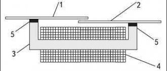
The machine consists of two disks, which are made of a good dielectric, such as ebonite, acrylic, etc. These discs are loosely mounted on an axle and can rotate around a horizontal axis. The disks themselves are arranged vertically. Using handle 1, both disks are rotated in different directions. One disk rotates clockwise and the other counterclockwise. This is achieved using drive belts 2 and 3, one of which is twisted 180° on one of the pulleys. This ensures multidirectional rotation of the disks, which is necessary for the induction of charges. Both discs rotate from the same handle and will therefore rotate simultaneously.
Metal strips 4 are glued to the outer part of each disk, which do not touch the edges of the disk, but are made at some distance from them. The stripes are arranged radially, in the form of rays emanating from the center of the disk. Both disks have the same number and arrangement of stripes; one can say that one disk is a reflection of the other.
When the disks rotate, the strips come into contact with brushes 5, which act as a contact for transferring charge along conductors 6, 7, 8 and 9. When operating the Wimshurst machine, the metal strips at the point of contact with the brushes can wear out and structurally this wear should be kept to a minimum, and Maximum contact reliability. Conductors 6 and 7 serve to remove and accumulate generated charges from both disks. Conductors 8 and 9 are each located on one side of the disk and connect diametrically opposite strips.
Thus we have two types of conductors. Some (6 and 7) are for removing charges, and 8 and 9 are for establishing a kind of “ground” - a line of neutral potential. Conductors 6 and 7 are located on the same geometric diametrical axis relative to the disks, and conductors 8 and 9 are rotated at an angle of 90° relative to each other.
You can also notice that between conductors 8 and 9, conductors 6 and 7 are located in the middle and are spaced at an angle of 45°. Thus, we see that the machine is structurally symmetrical and simple enough to make it yourself.
Electrical engine
Using power from the traction battery, the engine drives the car's wheels. Some vehicles use motor generators to perform drive and regeneration functions.
A classic electric motor consists of a conductive stator winding and a rotating rotor, which is driven by the magnetic field of the stator and transmits torque to the wheels. There are two types of electric motors: synchronous
, in which the magnetic field rotates simultaneously with the rotor, and
asynchronous
, in which the magnetic field rotates faster than the rotor.
The asynchronous motor changes the rotation speed depending on the frequency of the alternating current by simply pressing the accelerator pedal. This allows you to obtain, if desired, maximum torque for acceleration from a standstill.
Modern electric cars, depending on the power of the battery and engines, are capable of accelerating from zero to 100 km/h in 5-7 seconds, which is comparable to the acceleration of a car with a 250-350 hp engine. But the world's fastest production electric car, the Rimac C_Two, is capable of reaching 100 km/h in 1.85 seconds, faster than some 12-cylinder 6-liter supercars!
An undeniable advantage of electric cars is that the rotational torque of the electric motor is linearly transmitted directly to the wheels. While the internal combustion engine converts the translational movements of the pistons into rotation of the crankshaft and then through a system of gears and transmission clutches to the drive wheels. To overcome such an “obstacle course,” the car needs more power, which means more fuel and engine capacity.
On-board charger
Receives incoming AC power supplied through the charging port and converts it to DC power to charge the traction battery. It also communicates with charging equipment and monitors battery characteristics such as voltage, current, temperature and state of charge while the battery is charging.
Power electronics controller
: This unit controls the flow of electricity supplied by the traction battery, adjusting the speed of the electric traction motor and the torque it produces.
Cooling system
Maintains proper operating temperatures for motor, motor, power electronics and other components. During the cold season, excess heat from the battery can be discharged into the interior of the electric vehicle. For this reason, modern electric cars do not have a traditional stove.
Electric vehicle transmission
In the traditional sense, electric cars do not have a gearbox or cardan drive, since the electric motor operates efficiently in any speed range. Therefore, most electric vehicles have a single-speed gearbox located next to the inverter. This allows you to turn on the reverse mode, changing only the phases, and also direct the braking energy into battery charge.
A significant advantage of the electric motor and single-speed gearbox is that a “free” differential can be used. And in the event of slipping of one of the drive wheels, instantly take power from one of the drive axle shafts, reducing its slippage.
Chassis
The suspension system in electric cars is traditional and can often be borrowed from conventional cars. The main difference between the suspension of electric cars is that elastokinematics are forced to cope with more weight, while better weight distribution along the axles allows engineers to more accurately tune the handling to cope with the inertia of a heavy body.
Brake
The electric vehicle system is more cunning than usual. Traditional cars can effectively slow down when the brake pedal is pressed, and the braking energy is used to heat the brake pads and rotors. In electric vehicles, the electric motor can be used as a generator to charge the battery. When the accelerator pedal is released, the electronics detect a slowdown in the rotation of the magnetic field relative to the rotor and slow down the car. In this case, the brake pedal can only be used to completely stop the electric vehicle. Thanks to this, the service life of the brake mechanisms increases on average three times.
Application of electrophore machine
Since the 70s The Wimshurst machine is not used for direct production of electrical energy. Today it serves as a historical exhibit illustrating the history of the emergence and development of scientific and technological progress and engineering. A laboratory demonstration of why an electrophore machine is created shows the various phenomena and effects of electricity.
It is permissible to use induction neutralizers to remove charges from liquid dielectrics, such as oil. In any production environment, getting a spark in the air is dangerous; it can lead to harmful consequences, smoke and even an explosion.
The history of discoveries and research in the field of electricity is closely related to the use of various designs and devices for generating electrical charges. The electrophore machine, whose operation is based on the excitation of electricity through induction, played its role in scientific research.
Assembling the Wimshurst machine
In this video tutorial we will assemble an electrophore machine, which is a generator. At the beginning, general questions about the purpose and design of this machine are discussed, then all the steps for making it yourself are shown in detail.
What is an electrophore machine?
The device consists of a base on which its parts are attached. It also includes two racks with axles on which two disks with a metallized coating are mounted. There are also two Leyden jars, which are essentially capacitors or stores of charged particles. Dischargers, which function as the charge of the capacitors accumulate, remove charged particles from the front and rear sides of the disks. The discs are driven by a belt drive. We turn the handle and due to this, the disks rotate.
The first static electricity generators were simultaneously invented in Germany at the same time by August Toepler and, independently of him, by Wilhelm Goltz. The operating principle of an electrophore machine. As the disks rotate relative to each other in opposite directions, they create positive and negative charges. As the disks rotate, as charges accumulate, a discharge occurs.
The authors of the video decided to make this machine, which can be repeated with your own hands in normal home conditions. There are several examples on websites on the Internet of creating such a generator, but this design will have an engine.
First, drawings of the future machine were made. First of all, the disk parameters were calculated. After the preliminary work was done, we began to create the device.
Main details
The machine will consist of the following elements. These are 2 disks that will rotate in opposite directions, they will be made from CDs. Two motors from a computer cooler that will drive them. The disk will be glued with double-sided tape to the motor rotor. The engine itself is attached to the rack. The stands will be made of plexiglass. Leyden jars will also be used. This is an empty metal container from which there is one contact, then a polystyrene dielectric and a brass contact.
Manufacturing of electrophore machine
First you need to remove the coating from the disk to get a transparent blank. To do this we use a stationery knife. To create a working disk, you need sketches, they are made on a computer. The petal template can be made from a suitable material; a bank card is good for this.
Now, using the template, we begin marking on the tape. We attach the template and cut out all the necessary fragments. A total of 20 petals were cut out onto one disk. There should be 20 sections. The angle between the two petals is 18 degrees. Marking is done using a regular checkered sheet and a protractor. Now we place the disk exactly in the middle of the coordinates, using a knife or awl to make notches of 18 degrees. Glue the petals according to the lines. The second disc was made in exact analogy with the first disc. It has been machined to provide clearance.
Remove the yellow wire from the motor. We cut off the stiffeners so that the engine can be disconnected. Some space must be left for mounting holes.
Induction neutralizers
Neutralizers can become dirty during operation. Therefore, cleaning is required periodically, otherwise the efficiency will be reduced. In the Wimhurst machine, the fact of a decrease in efficiency plays little role. If the machine does not work, it is worth checking the cleanliness of the needles. The design uses four induction neutralizers:
- The twin equalizers lie almost perpendicular to each other.
- One puller for each Leyden jar.
They are a brush made of thin wire or sharp toothed flat combs (combs). The base can be metal, which is used in the Wimhurst machine, or wood. The tips are always metal, the purpose is to quickly remove the charge to grounding as quickly as possible. Operating principle: as the tips approach the charged plane, the tension lines close on them, forming high values.
For reference. The density of field lines is directly proportional to the intensity at a given point.
The increased density in the tip area promotes ionization of the air (without a spark) and the formation of charges of both signs, conducting current in the desired direction. The parameters of neutralizers strongly depend on the distance between the tips and the decrease in the radius of their curvature (sharpening). The wire brush neutralizers used in the Wimhurst machine are the least effective. The pullers have combs or needles. It is believed that for the latest neutralizers, maximum effectiveness is achieved under the following conditions:
- The ratio of the height of the needles to the distance between them is from 0.6 to 1.8.
- The length of the needles is 12 – 50 mm or more.
- The diameter of the needles is 0.5 – 1 mm.
Reducing the sharpening angle beyond 60 degrees (increasing curvature) in this case has little effect on the properties of the neutralizer. It is advisable to bring the needles at a distance of 5 mm to the surface. The closer, the faster the charge is removed. In fact, the minimum distance to the plane depends solely on the disc's own vibrations. Touching will not lead to system failure, but the service life will sharply decrease due to mechanical destruction of individual elements.
Contrary to the generally accepted opinion, created from endless demonstrations of the machine, it is better to mount the needles on a dielectric base. This step reduces the capacitance between the disk and the ridge, which increases the charge density: C = q/U. The charge is already given a priori; lowering the capacitance increases the potential difference (voltage), which facilitates the ionization process.
For safety, the neutralizer is equipped with a casing. It is worth recalling that other parts (besides the rotation handle) of the Wimhurst machine cannot be touched during operation. The edges of the casing are at least 50 mm away from the neutralizer needles.
The induction type of device is named for its action at a distance. The process is called electrostatic induction. This means that one charged object at a distance affects a second one without a charge. In a metal, electrons are weakly bound to the lattice and easily move in the direction where they are carried by the field. The effect is superficial for an obvious reason - tension lines cannot penetrate the metal. In another way: charges in the thickness of the conductor are redistributed until they completely neutralize the external field.
As a result, a charge is induced on the surface of the needle. The field strength lines close on it, simultaneously converging from everywhere, as shown in the figure. The potential difference increases immeasurably, causing ionization of the air. It is moderate; when the Wimhurst machine operates, there is usually no sparking on the brushes.
What is the operating principle of the device?
Since its invention (and this is the beginning of the eighteenth century), the electrophoric machine has gone through many changes. But the basic idea remains. The basis of the machine's design are discs with glued covers (metal strips). By applying a certain mechanical force using a belt drive, they can be rotated in different directions, opposite to each other. A positive charge appears on the lining of one disk. It will attract another charge (negative) to itself. The positive will go through a conductor with brushes (neutralizer), which touches the opposite plate. By turning the disks, we obtain charges similar to the original ones. But they will already affect other linings. Considering that the disks rotate in opposite directions, the charges flow to the collectors. In a demonstration apparatus such as an electrophore machine, the operating principle is based precisely on this point. On the brushes of both disks, which do not touch their surface and are located at the edges, the charges at some point become so huge that a breakdown occurs in the air space and an electric spark jumps. That is why additional capacitors of different capacities can be connected to the collectors, which will add greater beauty to the effect of the discharge.
The operating principle of a static electricity generator (also called electrophore machines) is that the disks rotate relative to each other in opposite directions and create positive and negative charges. When the disks rotate, as charges accumulate, a discharge occurs—lightning between the electrodes.
Work in thermodynamics
In thermodynamics, the work done by a gas during expansion is calculated as the integral of pressure over volume:
A1→2=∫V1V2PdV.{\displaystyle A_{1\rightarrow 2}=\int \limits _{V_{1}}^{V_{2 }}PdV.}
The work done on the gas coincides with this expression in absolute value, but is opposite in sign.
- A natural generalization of this formula is applicable not only to processes where pressure is a single-valued function of volume, but also to any process (represented by any curve in the PV
), in particular, to cyclic processes. - In principle, the formula is applicable not only to gas, but also to anything capable of exerting pressure (it is only necessary that the pressure in the vessel be the same everywhere, which is implicit in the formula).
This formula is directly related to mechanical work. Indeed, let's try to write the mechanical work during expansion of the vessel, taking into account that the gas pressure force will be directed perpendicular to each elementary area, equal to the product of pressure P
per area dS
area, and then the work done by the gas to displace
h
one such elementary area will be dA=PdSh.{\displaystyle dA=PdSh.} It can be seen that this is the product of pressure and the increment in volume near this elementary area.
And having summed over all dS
, we get the final result, where there will be a full increase in volume, as in the main formula of the section.
Design
The design of James Wimhurst's invention is poorly described in open sources; often people are unable to explain how the electrophore machine works.
General idea
Two coaxial disks rotating against each other carry simple capacitors made from aluminum sectors. Due to random processes, at the initial moment, a charge is formed on one of the segments - evenly spaced in a circle. This is caused by friction processes with air or other reasons. Moreover, since the design is symmetrical, the sign is not predictable in advance. It is not recommended to install electrolytic capacitors in the electrophore machine.
Instead, two Leyden jars are used. Their outer foil plates are combined to create a single system of capacitors connected in series. This reduces the operating voltage requirements for each container by half. The denominations are selected as identical as possible. Otherwise, the operating voltage requirements will be distributed unevenly, leading to negative consequences.
The voltage from the disk segments is removed using induction neutralizers. The principle of operation is described below. Essentially, a structure resembling a metal comb floats above the disk at a certain height. The neutralizers are paired; both disks arrive at the charge removal point with an equivalent sign on the outer surface. After unloading, the charge of the segments drops significantly. This is due to the special design of induction neutralizers, leaving a surface charge density in the region of 0.2 - 6 μC per square meter. In selected designs, the brush lightly touches the edge of the disc.
The progressive increase in the surface charge density on the segments at the point of removal is due to the fact that systems are moving towards each other, creating electric fields whose strengths are directed in opposite directions. It turns out that with his own hand the operator (or through the force of an electric drive) forcibly brings the repulsive systems together. The interacting charges try to position themselves further away from each other. This causes a sharp increase in the surface charge density at the removal points.
From the neutralizer combs, electricity is collected in Leyden jars. The voltage rises quickly, in order to avoid system failure due to exceeding the permissible parameters of the capacitors, a spark gap is attached to the two electrodes. The distance between them is usually adjustable, which allows you to obtain an arc of varying strength. The higher the field strength between the spark gaps, the more noisy the process of emptying the Leyden jars.
After the charge removal point, the segments remain empty. At 30 degrees in the direction of motion of the disk there are potential equalizers, called neutralizers based on their operating principle. The authors of the review would call them equalizers. The opposite sides of the disk have already given up charge from different brushes. Consequently, after passing the removal point, the signs of the remaining charge on them are invariably different. And a piece of thick copper wire with brushes of thin wires, rubbing the segments or hovering at a low altitude, short-circuits the indicated opposites. As a result, the charge on both segments becomes zero, the energy is converted according to the Joule-Lenz law into heat released on a thick copper core.
After zeroing, the disks continue to move in the opposite direction. It turns out that a segment of one circle of rotation, freed from charge, turns out to be opposite the half-empty segment of another. The charge between the containers is immediately divided equally, because the disks are designed according to the same drawings. Therefore, they appear identical. The first disk releases half its charge and goes to the removal point. The second reaches the point of potential equalization of the first and there gives up half the charge.
Sometimes people are interested in the principle of operation of the device, because the first disk gave up the residual charge on the equalizer, the second did the same. Where can I get the energy to change the sign?
- https://odinelectric.ru/knowledgebase/chto-takoe-elektrofornaya-mashina-i-kak-ona-rabotaet
- https://fb.ru/article/136480/elektrofornaya-mashina—printsip-rabotyi-kak-sdelat-elektrofornuyu-mashinu-svoimi-rukami
- https://vashtehnik.ru/enciklopediya/elektrofornaya-mashina.html
Electrophore machine design
2 coaxial disks rotate against each other, while carrying simple capacitors made of aluminum sectors. Thanks to random processes, at the initial moment a charge is formed in a section of one of the segments. The phenomenon is caused by the process of friction with air. Due to the symmetry of the design, the final sign cannot be predicted in advance.
The design uses 2 Leyden jars. They create a single system from series-connected capacitors. This has the effect of doubling the operating voltage requirements in each container. The same ratings should be selected, this is the key to uniform distribution of operating voltage.
Induction neutralizers are designed to relieve tension. The entire structure resembles a metal comb floating at some distance above the disk. Both disks with equivalent signs of the outer surface arrive at the charge removal point. The neutralizers are paired. After unloading, the charge of the segments is greatly reduced. In additional designs, the brush easily contacts the edge of the disc.
Is the Wimshurst machine a power generator?
More precisely, we can say that the Wimshurst machine is a converter of mechanical rotational energy into the energy of an electrostatic field. When operating such a machine, like any other, there are friction losses, energy leaks, etc. Therefore, its efficiency cannot be more than 100%, and even it cannot be equal to 100%.
As the potential difference grows, the more charge accumulates, the stronger the Coulomb forces will counteract the mechanical ones. In practice, this means that with each revolution of the discs the applied force will increase. In addition, there will be friction losses in the structure and unwanted charge leakage.
Date: 05/12/2015
How it works - theory
The rotation of disks with metal sectors leads to the transfer of electrical charge inside the machine, which is stored in capacitors until a spark or leakage charge occurs.
The most important parts in an electrophore unit are neutralizers. These are two jumpers with brushes installed in a cross. If at least one of the four brushes is moved away from the segments, the machine stops working. Although it would seem that the disks are rotating, they are electrified by friction with the air, which means electricity is generated.
The neutralizer does the following: it drags the charge from one half of the disk to the other and the disk is not just charged, but selectively charged - not over the entire plane.
In other words, the disk collects charges from the air, and the neutralizers redistribute them. The charge is removed by the brush, moves along the conductor to the opposite brush, and at the moment when a segment of the second disk appears opposite the segment, it jumps to it.
Next, this segment approaches the brush of the second neutralizer and the process is repeated, but on another disk. Thus, a circulation of charges occurs between the disks, during which the air between the segments is ionized and separated. As a result of pumping, the voltage increases; in addition, the machine has the effect of moving the capacitor plates apart, which also helps to increase the voltage.
A miniature device for creating such harmless lightning (but not for microelectronics) is easy to make with your own hands.
This electrostatic generator is capable of generating over 20,000 volts, but the low current makes it safe to use without special precautions.
§3 Modern machines, their scope.
People taught electricity another profession - to drive cars. The driver turns the switch handle. Powerful electric motors begin to rotate the wheels of the electric locomotive, and the train moves smoothly along the rails.
Where does the engine get such power? Scientists have noticed that if currents flow in two parallel wires in the same direction, then the wires attract each other, and if currents flow in different directions, the wires tend to repel each other. The forces of interaction between conductors and current make electric motors rotate.
Practical part