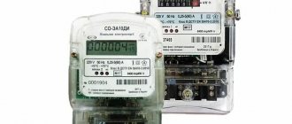
Methods for connecting machines in a distribution panel
In distribution cabinets and lighting panels, several similar circuit breakers, automatic circuit breakers or RCDs (residual current devices) are often installed on one DIN rail.
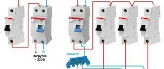
In these cases, power is supplied to the switching devices via the main line (loop). There are two ways to connect circuit breakers to each other.
The machines can be connected using wire jumpers or using connecting bars (combs) produced by industry.
Useful tips
Sometimes connecting a circuit breaker is associated with the correct implementation of some nuances of the entire process. Namely, by connecting wires to the device. What do you need to pay attention to?
- Each model has its own requirements regarding the cross-section of the inserted wire and the length of the insulating sheath. This must be indicated in the product passport.
- Most often, the wire needs to be stripped to a length of 0.8 to 1.0 cm.
- It is important to understand that placing a wire with insulation in a clamp is unacceptable, because the diameter of the insulation is larger than the diameter of the core itself, so the contact between the clamp and the core will either be weak or completely absent.
- The wire is fixed in the machine with a screw, which is tightened with a screwdriver. After fixing, you need to check the quality of the clamp; to do this, the wire itself must be tugged slightly.
- If a stranded conductor is used to connect the machine, then it is best to put a tip on its end.
Jumper wires
Electricians usually make jumper wires themselves. Any single-core insulated wire of suitable cross-section is suitable for making jumpers.
It is recommended to use single-wire wire PV-1 or multi-wire (flexible) wire PV-3 in vinyl insulation.
The process of making jumpers is simple. First, the length of the conductor is measured and the required number of wire segments is cut. The wires are stripped at both ends.
The length of the bare part of the wire should be 12mm. Then the wire is bent, giving the jumper the desired shape. If a flexible wire is used, lugs are pressed onto the bare ends using press pliers.
An example of connecting machines using jumpers.
The cross-section of the wire for making jumpers must be selected based on the sum of the rated currents of all circuit breakers connected to the first circuit breaker in the loop.
To ensure high-quality contact, it is desirable that the ends of the jumpers connected to one terminal of the machine have the same cross-section.
Often electricians make jumpers between machines from one continuous wire. The appearance of such a jumper attached to the machines is shown in the figure below.
Connecting machines using jumpers has its advantages and disadvantages.
The disadvantages of this connection method include:
- High complexity of manufacturing jumpers. This is especially noticeable with large volumes of electrical installation work.
- If the DIN rails are located close to each other in the panel, the jumpers may interfere with the connection of conductors to the circuit breakers of the top row.
The advantages of using jumpers include low manufacturing costs. If the jumpers are made of unbreakable wire, then it is possible to replace a failed circuit breaker without turning off other circuit breakers.
To do this, disconnect the jumpers from the upper terminals of the machine, put pieces of insulating tube on them, remove the faulty device from the DIN rail and install a new one. Then connect the power wires.
Electric machines. Types and work. Characteristics
From the very beginning of the emergence of electricity, engineers began to think about the safety of electrical networks and devices from current overloads. As a result, many different devices have been designed that are distinguished by reliable and high-quality protection. One of the latest developments is electric automatic machines.
This device is called automatic because it is equipped with a function to turn off the power in automatic mode in the event of short circuits or overloads. Conventional fuses must be replaced with new ones after tripping, and the circuit breakers can be turned on again after eliminating the causes of the accident.
Such a protective device is necessary in any electrical network circuit. A circuit breaker will protect a building or premises from various emergency situations:
- Fires.
- Electric shocks to a person.
- Electrical wiring faults.
Types and design features
It is necessary to know information about the existing types of circuit breakers in order to correctly select the appropriate device during purchase. There is a classification of electric machines according to several parameters.
Breaking capacity
This property determines the short circuit current at which the machine will open the circuit, thereby turning off the network and devices that were connected to the network. Based on this property, machines are divided into:
- 4500 ampere circuit breakers are used to prevent faults in the power lines of older residential buildings.
- At 6000 amperes, they are used to prevent accidents during short circuits in the network of houses in new buildings.
- At 10,000 amperes, used in industry to protect electrical installations. A current of this magnitude can occur in the immediate vicinity of a substation.
The circuit breaker trips when a short circuit occurs, accompanied by the occurrence of a certain amount of current.
The machine protects electrical wiring from damage to insulation by high current.
Number of poles
This property tells us about the largest number of wires that can be connected to the machine to provide protection. In the event of an accident, the voltage at these poles is switched off.
Features of machines with one pole
Such electrical circuit breakers are the simplest in design and serve to protect individual sections of the network. Two wires can be connected to such a circuit breaker: input and output.
The purpose of such devices is to protect electrical wiring from overloads and short circuits of wires. The neutral wire is connected to the neutral bus, bypassing the machine. Grounding is connected separately.
Electrical machines with one pole are not input, since when it is disconnected, the phase is broken, and the neutral wire still remains connected to the power supply. This does not provide 100% protection.
Properties of machines with two poles
In cases where an emergency requires complete disconnection from the electrical network, circuit breakers with two poles are used. They are used as introductory ones. In emergency situations or in the event of a short circuit, all electrical wiring is switched off at the same time. This makes it possible to carry out repair and maintenance work, as well as work on connecting equipment, since complete safety is guaranteed.
Two-pole electrical circuit breakers are used when it is necessary to have a separate switch for a device operating on a 220-volt network.
A machine with two poles is connected to the device using four wires. Of these, two come from the power supply, and the other two come from it.
Three-pole electrical circuit breakers
In an electrical network with three phases, 3-pole circuit breakers are used. The grounding is left unprotected, and the phase conductors are connected to the poles.
The three-pole circuit breaker serves as an input device for any three-phase load consumers. Most often, this version of the machine is used in industrial conditions to power electric motors.
Using busbars
The industry offers two types of combs for connecting modular switching devices. In one type of comb bus, the contacts are made in the form of pins. Another type has fork-shaped contacts.
The combs consist of conductive bars (usually copper) with contacts and a plastic insulating body. The distance between the contacts is equal to the width of one module and is 18 mm. Connecting busbars can have from 1 to 4 poles.
Each pole fits into a separate groove in the housing and is reliably isolated from other conductive busbars. Using a comb bus, you can connect both single-pole circuit breakers and three-phase RCDs.
Connection busbars are available with 12, 24, 36 or 48 modules. The tires can be cut to obtain the required number of modules. For cutting, you can use any suitable tool, such as a hacksaw.
The following technical characteristics are marked on the tire casings:
- cross-section of conductive busbars.
The pin connection bars are suitable for all types of modular switching devices. To use buses with fork contacts, machines must have special terminals.
The use of combs requires greater material costs than the use of wire jumpers. However, the use of connecting busbars significantly reduces the installation time.
In addition, installation performed using combs looks more aesthetically pleasing. There is more space in cabinets and panels.
The disadvantages of using connecting buses include the impossibility of replacing faulty circuit breakers or RCDs without disconnecting adjacent switching devices.
To summarize, we can say that it is better to use jumpers when there is a small number of modular devices on the rail. In the case of a large installation volume, it is advisable to use connecting bars.
Connection diagrams
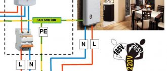
So, the operating principle of the circuit breaker is now clear, you can proceed directly to its connection diagrams. Let's start with the fact that machines can be connected to single-phase and three-phase networks. What machines are needed for this? If the conversation is carried out from single-phase networks with a voltage of 220 volts, then either a single-pole device or a two-pole device is usually installed in them. The circuit itself will depend on whether it uses a ground loop or not.
If two wires enter the house (zero and phase), then a single-pole version can be installed in the distribution cabinet. In this case, the phase circuit will pass through the machine itself. If three wires enter the house (phase, neutral and ground), then the common circuit breaker must be two-pole. That is, a phase is connected to the first terminal of the device, and zero to the second. Grounding is routed to consumers (lights and sockets) through a separate terminal box. Next, the wires from the circuit breaker are routed to the meter, then to single-pole circuit breakers installed in groups, but as described in the first case. By the way, below is the system for connecting the machine.
As for the three-phase network, in this case it is best to install three-pole or four-pole structures. Everything here is exactly the same as in the case of a single-phase connection. That is, if the house uses wiring without grounding, then three phases of the power supply are connected to the fixed contacts. The neutral wire is routed as a separate circuit to consumers (sockets and lamps). If the house has a grounding system, then a four-pole model is installed, that is, three phases and zero will be connected to the device, and the grounding loop will go as a separate line to consumers.
How to connect a machine in a control panel - bringing knowledge to the masses
The distribution board contains a whole set of modular devices responsible for protecting the entire electrical network of the house. Such a team includes all kinds of relays, circuit breakers, circuit breakers and much more.
To install all this, we invite electricians, whom we rely on as professionals, but not all technicians carry out the installation correctly. In practice there are many errors.
Today we will discuss how to connect the machine in the panel. This information will be useful not so much for doing the work yourself (you need access for this), but for monitoring the activities of hired specialists.
A little theory
It is known from the physics course that there is a relationship between electrical power, current strength and voltage in the electrical network. In a simplified form, this relationship is expressed by the following formula for a single-phase network:
where W is the current power in watts (W);
I – current strength in amperes (A);
V – voltage in volts (V).
In this case, we will be interested in the current strength, since the circuit breaker and electrical wiring characteristics are often selected based on this parameter. For convenience, we transform the above formula into the expression:
As an example, let’s calculate the current strength for the load that the energy-intensive consumers mentioned above provide to the power grid. Their total power will be about 6 kW, and at a voltage of 220 V we get the current in the circuit:
I = 6000 W / 220 V = 27.3 A
For a three-phase connection diagram, formula (2) will take the following form:
This change is caused by the fact that with an equal load and uniform distribution of power across phases, the current in a three-phase network will be three times less. Thus, with the same total power of 6 kW, but at a voltage of 380 V, the current in the circuit will be equal to:
The procedure for connecting machines - what you should always remember
It would seem, what could go wrong when connecting a single-pole circuit breaker?
The technician’s task is to strip the wire of insulation, thread it inside the terminal and tighten it! However, we are full of people with arms growing in the wrong places.
Sorry for such open indignation, but sometimes you just can’t say it any other way. And sometimes mistakes happen among professionals (this is less common), since we are all human, we can get sick, get tired, be overwhelmed with problems and other things that will prevent us from doing our work efficiently.
So, we got carried away with something. Let's get down to business. We will start with the most important thing - the correct connection of the machines in the panel. Such a switch has two contacts through which it is connected to the network.
One of them is movable, and the second is fixed; they are located at the top and bottom of the device. Do you know which one needs power? Imagine, very few people know about this, since there are constantly debates on this topic on “electrical” forums.
We will not engage in introspection and will turn directly to the PUE, 7th edition, paragraph 3.1.6. It says the following. If the device is powered one-way, then the supply conductor must be connected to a fixed contact.
However, it is worth noting that there is a disclaimer in the form of the phrase “as a rule”, this is a little confusing, as if there are cases that allow an exception to this recommendation. But no further explanations are provided.
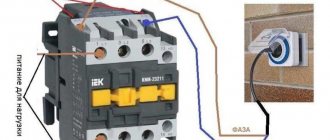
The same rule applies to all protective devices, circuit breakers and RCDs. To understand where the machine is and what contact is located, you need to know how it works from the inside. Let's dive a little deeper into the world of electrical engineering and look at the structure of a simple single-pole circuit breaker.
- You don’t need to be an engineer to notice that the upper contact of such a machine is fixed, and the lower one is movable. It is not necessary to disassemble the device to recognize the types of contacts. You can also use the markings on its body. Look at the next photo.
The markings on switches from other companies may be slightly different, but, in general, everything is very clear there too. As a last resort, you can always find information on the Internet by making a request for a specific model. In general, almost all modern single-pole circuit breakers have exactly the same arrangement of contacts, but you must make sure of this.
Now let's try to understand the issue from a purely technical approach. So, top or bottom?
- The purpose of the circuit breaker is to protect the line connected to it from short circuits and overloads. It works like this - when overcurrents appear in the circuit, a reaction occurs between the thermal and magnetic releases, which are located inside the device body. At the same time, there is no difference in which side the power cable is connected; the device will work in any case.
- This is confirmed by the fact that some manufacturers, for example, Hager or ABB, allow reverse connection of power to the machine. For these purposes, they are specially equipped with clamps for comb tires.
Batch circuit breaker
- Description
- Why do you need a package?
- Types and purpose of packets
- Design and principle of operation
- Marking
- Batch switch connection diagram
To switch the load or completely disconnect it, special devices are used in alternating current circuits. One of them is an electric package or a package circuit breaker used in domestic conditions. Currently, most packages have been replaced by modern automatic protective switches.
All package switches belong to low-voltage electrical devices that perform switching in electrical circuits. Structurally, a packet switch can have one, two or three poles. Colloquially among specialists, these devices are also called packets.
A standard package switch consists of a housing, a handle, a switching mechanism and a contact system, including movable and fixed contact groups. Extinguishing the electric arc that occurs under load during switching is carried out by a spring-loaded quick switching mechanism. The main difference between a packet switch and a differential circuit breaker is the impossibility of disconnecting it from the supply network. When large voltage drops occur, the packet may simply burn out.
The main advantages of these devices are their compact size and the availability of a large switching resource. They provide a high degree of electrical safety during switching operations. Previously, small-sized packet switches were installed in every apartment or house. Currently, they are being replaced by two- or three-pole circuit breakers.
How to connect to the machine correctly?
At work, our main three-phase circuit breaker (imported), which powers the entire building, burned out. We're going to replace it. At the input of the machine, three wires of 16 squares are soldered at the ends. At the output there are three short stranded wires of the same cross-section. We were asked to put tubes on the ends of the output wires, crimp them with press pliers and put them into the machine. However, doubts arose. Stranded copper wire is soft and easily takes the semicircular shape of the holes in the machine. If you put tubes on it and crimp it, then the ends of the wires will become rigid; their profiles will not coincide with the profile of the holes in the machine and the contact surface will decrease, the contact will become point-like. The wires in the machine are clamped through plates with five-point screws, so it is unlikely that the ends of the rigid wires will be deformed and take the desired shape. Please advise what to do correctly. Are there any regulatory documents?
It is not very good to connect a stranded wire as it is to a machine. If it is not possible to solder it in a crucible, then crimping or NShVI lugs (12 or 18 mm long, depending on the design of the terminals of the machine) would be a better option.
Message for rikitiki. Photos of those arriving if possible. And it wouldn’t be a bad idea to replace the circuit breaker (if it needs to be changed).
rikitiki wrote: attach tubes to the ends of the output wires, crimp them with press pliers and put them in the machine
perfect. But it is also possible without tips - machine manufacturers, as a rule, allow both options without restrictions.
Message for evgenygrig. They admit it (not everyone), but what kind of machine really is?
It’s better to solder the strand and clamp it in AB just like that, although if the machine has a “floating clamp” type terminal, and not a stud/nut, in this case the strand must be crimped into the tip
rikitiki wrote: At work, our main three-phase circuit breaker (imported) burned out.
rikitiki wrote: At the input of the machine, three wires of 16 squares are soldered at the ends
Are there any signs of burning in this area?
Thank you all very much for your answers. On Monday, when I go to work, I’ll take macro photos of the machine and its connections, and also look at its brand, disassemble it and take a photo of the burnt one. I will also note that in appearance and size it is like other machines designed for lower current and is attached in a row with others by snapping onto a metal plate. The color of the machines is white. Since the AV is the main one, it is designed for a higher current. When measured by a tester, the current in each phase was
50 A Moreover, a significant increase in this value cannot be ruled out if all consumers turn on at the same time. amateur1 gave an exact definition that I could not find - the machine has a “floating clamp” type terminal. This is a very common, widely used type of imported machine.
rikitiki wrote: This is a very common, widely used type of imported machine.
Regular modular machine. And why imported? It's as if they don't make them in Russia.
rikitiki wrote: the machine has a “floating clamp” type terminal.
rikitiki wrote: At the input of the machine, three wires of 16 squares are soldered at the ends
rikitiki wrote: main three-phase
rikitiki wrote: When measuring with a tester, the current in each phase was
rikitiki wrote: Moreover, a significant increase in this value is not excluded if all consumers turn on at the same time.
and no one ever does a control broach. maybe that was the reason.
Crimping is both faster and cheaper. Although, at the beginning of my career, one smart energy supervision engineer taught me how to solder the ends of multi-core wires. But this requires skill and dexterity. Crimping is easier to do. This means less influence of the human factor. One day, out of idleness, a customer looked into the panel and urgently called me: “your wires all got so hot that the insulation on them melted.” I arrive, and sure enough, when the wires were soldered, the insulation melted slightly. Explained.
massmeter wrote: “your wires all got so hot that the insulation on them melted.” I arrive, and sure enough, when the wires were soldered, the insulation melted slightly.
Not when they soldered it, but when the tin floated and the contact began to break down.
massmeter wrote: Crimping is easier to do. This means less influence of the human factor.
and the correct choice of sleeve/tip and crimp head size are not subject to FACTOR.
rikitiki wrote: Thank you very much everyone for your answers. On Monday, when I go to work, I’ll take macro photos of the machine and its connections, and also look at its brand, disassemble it and take a photo of the burnt one. I will also note that in appearance and size it is like other machines designed for lower current and is attached in a row with others by snapping onto a metal plate. The color of the machines is white. Since the AV is the main one, it is designed for a higher current. When measured by a tester, the current in each phase was
Purpose
It is important not to confuse: the entrance is from above, the exit is from below, otherwise the machine may fail and will not perform its functions. Video about circuit breakers. The machine is mounted on a rail using a spring-loaded latch at the bottom of the case
In the practice of using such equipment, there is a frequent use of three types of devices: single-pole, two-pole, three-pole. Photo - two-pole circuit breaker This implementation is provided for by the PUE Rules for Installing Electrical Equipment, which states that it is prohibited to disconnect the phase wire without disconnecting the neutral.
Features of the operation of single-pole and double-pole AV
Also, the selection of a machine based on the value of the long-term permissible current should be made depending on the characteristics of the wiring cable.
The thermal release protects the circuit from overloads, and the electromagnetic release from short circuit overcurrents. An example is shown in the picture. In this case, it is imperative to observe the condition of insulation integrity everywhere except the terminal blocks.
In the case when the RCD has tripped, it is necessary to find a fault in the circuit. The electric current, cut off on one wire, may remain on the other. It is designated by letters of the Latin alphabet and applied to the body of the circuit breaker itself. Connecting a differential machine
How to connect a thick cable to a machine?
It often happens that wires of different sections come into the junction box and they need to be connected. It seems like everything should be simple here, as with connecting wires of the same section, but there are some peculiarities here. There are several ways to connect cables of different thicknesses.
Remember that you cannot connect two wires of different sections to one contact in a socket, since the thin one will not be pressed tightly by the bolt. This will lead to poor contact, high contact resistance, overheating and melting of the cable insulation.
How to connect wires of different sections?
1. By twisting with soldering or welding
This is the most common way. You can twist wires of adjacent sections, for example 4 mm 2 and 2.5 mm 2. Now, if the diameters of the wires are very different, then good twisting will no longer work. When twisting, you need to make sure that both wires wrap around each other. Do not allow a thin wire to wrap around a thick one. This may result in poor electrical contact. Do not forget about further soldering or welding. Only after this will your connection work for many years without complaints.
2. Using screw clamps ZVI
I already wrote about them in detail in the article: Methods of connecting wires. Such terminal blocks allow you to insert a wire of one cross-section on one side, and a different cross-section on the other side. Here each core is clamped with a separate screw. Below is a table that will help you choose the right screw clamp for your wires.
| Screw clamp type | Cross-section of connected conductors, mm 2 | Permissible continuous current, A |
| ZVI-3 | 1 – 2,5 | 3 |
| ZVI-5 | 1,5 – 4 | 5 |
| ZVI-10 | 2,5 – 6 | 10 |
| ZVI-15 | 4 – 10 | 15 |
| ZVI-20 | 4 – 10 | 20 |
| ZVI-30 | 6 – 16 | 30 |
| ZVI-60 | 6 – 16 | 60 |
| ZVI-80 | 10 – 25 | 80 |
| ZVI-100 | 10 – 25 | 100 |
| ZVI-150 | 16 – 35 | 150 |
As you can see, using ZVI you can connect wires of adjacent sections. Also remember to look at their amperage rating. The last digit in the screw terminal type indicates the amount of permissible continuous current that can flow through this terminal.
We strip the wires to the middle of the terminal.
We insert them and tighten the screws.
3. Using Wago universal self-clamping terminals.
Wago terminal blocks have the ability to connect wires of different sections. They have special sockets where each wire “sticks” into. For example, you can connect a 1.5 mm 2 wire into one hole of the clamp, and 4 mm 2 into the other, and everything will work properly.
According to the manufacturer's markings, terminals of different series can be used to connect wires of different sections. See table below:
| Wago terminal series | Cross-section of connected conductors, mm 2 | Permissible continuous current, A |
| 243 | 0.6 to 0.8 | 6 |
| 222 | 0,8 – 4,0 | 32 |
| 773-3 | 0.75 to 2.5 mm 2 | 24 |
| 273 | 1.5 to 4.0 | 24 |
| 773-173 | 2.5 to 6.0 mm 2 | 32 |
Below is an example with series 222.
4. Using a bolted connection.
A bolted connection of wires is a composite connection consisting of 2 or more wires, a bolt, a nut and several washers. It is considered reliable and durable.
Here it goes like this:
- we strip the core by 2-3 centimeters, so that it is enough for one full revolution around the bolt;
- we make a ring from the core according to the diameter of the bolt;
- take the bolt and put it on the washer;
- We put a ring of conductor of the same section on the bolt;
- then put on the intermediate washer;
- put on a ring made of a conductor of a different cross-section;
- We put the last washer and tighten the whole thing with a nut.
In this way, you can simultaneously connect several wires of different sections. Their number is limited by the length of the bolt.
5. By squeezing the branch “nut”.
I wrote about this connection in detail with photographs and corresponding comments in the article: Connecting wires using nut-type clamps. Let me not repeat myself here.
6. Using tinned copper tips through a bolt with a nut.
This method is well suited for connecting large cross-section cables. For this connection, it is necessary to have not only TML tips, but also crimping pliers or a hydraulic press. This connection will be a little bulky (long), and may not fit into some small junction box, but it still has the right to life.
It's easy to connect here. A ferrule is placed on each core, they are crimped and connected using a bolt with a nut and washers. This area is then insulated using insulating tape or heat-shrinkable tubing (it must be placed over the wire before connection).
Unfortunately, I didn’t have a thick wire and the necessary tips on hand, so I made a photo from what I had. I think you can still understand the essence of the connection from it.
I think I've listed everything. If you know other ways to connect wires of different sections, then write in the comments.
There are two people sitting in a cell: “Why are you in prison?” - For murder. - How much did they give? - 7 years. What are you for? - For poaching. - How many? - Fifteen. – Who were you hunting for?! “I’m walking, so I’m hunting, I see a telegraph pole, an eagle sitting on the pole.” Well, I'm a doublet. - So what?! 15 years for an eagle? Did you even kill him? - Yeah... he shot, claws in one direction, pliers in the other.
Oven socket
Many people have a question: is it possible to connect an electric oven from an existing regular outlet that was previously installed in the kitchen for a kettle, microwave, etc.?
It is possible, the main thing is that 3 conditions are met:
the oven must have a power of no more than 3.5 kW
The socket is connected with a three-core copper cable from the panel with a cross-section of at least 2.5 mm2
in the electrical panel, replace a conventional circuit breaker with a thermal release with a differential circuit breaker with a rated current of no more than 16A
If you replace the only circuit breaker for sockets with a differential 16A one and connect the oven through it, it will be practically impossible to use other electrical appliances while the oven is working and food is being prepared.
Here you will have to make your own choice, either in favor of saving (not installing new wiring, a separate outlet, etc.), or in favor of comfort and convenience. It is not recommended to leave a regular modular machine in the panel without protection against leakage currents when connecting the oven to an old outlet.
The height of installation of a new socket under the oven should be no more than 90cm from the floor. Although it is also often placed at the level of the kitchen legs.
The most important thing here is ease of use. For safety reasons, when wet cleaning and wiping the oven with a wet cloth, it must be disconnected from the power supply.
And crawling under the very bottom of the kitchen every time to pull out the plug is not always convenient. In addition, here you need to take into account possible situations such as water leaks and kitchen flooding. Therefore, the socket should still be raised 5-10cm above the floor.
The main requirement for placing the outlet is not to place it directly behind the oven. You can install it on the left, on the right, or as mentioned above - under it, directly near the floor.
Another safety point when installing an outlet: if there is a gas supply nearby, for example to a hob (let’s say you have a gas supply and not an electric one), then the outlet should be at least 60cm away from it.
When you have decided on the location of the outlet, you need to connect it.
Connect the phase and neutral cores of the cable to the outermost contacts of the socket
In this case, it does not matter at all where the phase will be located, and where the zero is - on the right or on the left. Connect the grounding conductor (yellow-green) to the grounding terminal (usually the middle one)
Replace the frame or decorative cover.
Methods for connecting wires of different sections
Connecting copper wires of different thicknesses is not the most difficult process. However, for maximum reliability and safety, certain requirements must be observed here. There are several ways to connect three wires of different cross-sections:
- welding or soldering;
- using screw clamps;
- using self-clamping terminals;
- bolted connection;
- branch compression;
- using copper tips.
Three wires of different cross-sections can be reliably connected using any of the listed methods, but it is important to remember that when installing sockets and switches, cables of different thicknesses cannot be connected to one contact. In this case, the thinnest one will not be pressed tightly enough. And this, in turn, can negatively affect operational safety.
Wire selection
The requirements for cable products are determined by the conditions in which the product will operate.
The shield is a device with limited space, so miniature and compactness are one of the main selection criteria. Reliability and durability are no less important for such products. The cable must bend well and withstand bending, so devices with an aluminum core are not suitable. All conductors can be divided into classes based on flexibility. This indicator depends on the design of the cores. The higher the class, the more flexible the conductor. Monolithic conductors are difficult to bend and can break during operation, but they are easy to connect to the terminals. Stranded products bend better and are easier to work with, but the difficulty lies in the impossibility of connecting to terminals and screw clamps. To do this, you have to either tin the ends or crimp them with special tips. Otherwise, the contact will be unreliable and will not last long. The choice of stranded or solid wire also depends on the flexibility class of the product.
Connecting wires of different sections by welding or soldering
The simplest, but fairly reliable way to connect cables that have different thicknesses. In this case, three wires can be connected to each other using rigid twisting and subsequent fixation. But here it should be remembered that a reliable connection is only possible between wires of approximately the same cross-section. Twisting of wires whose diameters differ significantly cannot be reliable.
You need to carefully twist three wires of different sections together. Each copper wire should tightly wrap around the adjacent one. The gaps between them should be minimal. Otherwise, this will affect the safety of subsequent operation.
Before you begin directly twisting the three wires, lay them out in front of you and sort them by thickness. You cannot wind a thin wire onto a thick one - this will affect the quality of the contact. Such a connection will not last long.
What is wire twisting and why is it dangerous?
Several decades ago, when the load on electrical wiring was not so great, such a connection was popular. Moreover, experienced craftsmen taught me, then a young electrician, to first thoroughly strip the metal cores, twist them tightly, and crimp them with pliers.
The length of this twist had to be created on the order of 10 cm to ensure good electrical contact, as shown in the lowest example. And they would reject anything higher, despite its beauty.
Inside closed, dry rooms, such twists worked for years and decades. However, many electricians violated the technology and created poor-quality contact.
In addition, in a humid environment, the metal oxidizes. The electrical resistance of its transition surface layer deteriorates. This leads to increased heating of the cores and premature damage to the insulation.
Therefore, modern rules, in particular the PUE, prohibit simple twisting of wires, no matter how beautifully and reliably it is done.
Particularly dangerous are twists of aluminum wires, as well as cores made of different metals - copper and aluminum.
This is due to the high ductility of soft aluminum and its high ability to create, under the influence of atmospheric oxygen, an outer layer of oxides that protects the internal structure of the metal. This film reduces conductivity.
When currents flow with increased loads, aluminum, which has a high coefficient of linear expansion, heats up, increasing its volume. After cooling, it contracts, breaking the tightness of the joint.
Each heating and cooling cycle degrades the electrical performance of the strand. In addition, copper and aluminum work as a galvanic couple, and these are additional chemical reactions with the formation of surface oxides.
Recommendation: wherever you find a simple twist, get rid of it. Reinforce it by soldering, welding, crimping or any other approved method.
Connecting three wires of different sections using screw terminals
Three wires of different thicknesses can be reliably connected to each other using special ZVI screw clamps. The clamps have a very convenient design and allow you to create contact between cables that have different cross-sections. The strength of the connection is achieved by using separate screws for each clamp.
You need to select ZVI clamps taking into account the cross-section of the wires that will be connected, as well as their current load. For reliable contact, it is recommended to connect three wires of adjacent sections. Let us conventionally designate the cross-section of the connected conductors as SPP, and the permissible long-term current as DDT. Below are the parameters of clamps and wires:
- ZVI-3 – SPP 1 – 2.5; DDT – 3;
- ZVI-5 – SPP 1.5 – 4; DDT – 5;
- ZVI-10 – SPP 2.5 – 6; DDT – 10;
- ZVI-15 – SPP 4 – 10; DDT – 15;
- ZVI-20 – SPP 4 – 10; DDT – 20;
- ZVI-30 – SPP 6 – 16; DDT – 30;
- ZVI-60 – SPP 6 – 16; DDT – 60;
- ZVI-80 – SPP 10 – 25; DDT – 80;
- ZVI-100 – SPP 10 – 25; DDT – 100;
- ZVI-150 – SPP 16 – 35; DDT – 150.
With the right choice of screw clamp, you can create a truly reliable connection that will ensure uninterrupted operation of the electrical network.
What are distribution boxes for?
There are many factors that speak in favor of the existence of junction boxes:
- The power system can be repaired in a matter of hours. All connections are accessible, you can easily find the area where the wires have burned out. If the cable was laid in special channels (corrugated tube, for example), then the failed cable can be replaced in an hour;
- Connections can be inspected at any time. As a rule, wiring problems occur at the connection points. If the socket or switch does not work, but there is voltage in the network, first check the quality of the connection in the junction box;
- the highest level of fire safety is created. It is believed that dangerous places are connections. Using a box will keep them in one place.
- minimal time and financial costs when repairing wiring. There is no need to look for broken wires in the walls.
Connect wires of different sections using bolts
Another way to connect wires of different sections to each other is to create contact using bolts, washers and nuts. According to professional electricians, this connection is the most durable and strong. The process itself is not too complicated and takes minimal time. The procedure goes as follows:
- the copper conductors of the wire are carefully stripped (the length of the stripped section of the conductor depends on the diameter of the bolt);
- the stripped core is bent into a loop;
- the loop is put on the bolt;
- an intermediate washer is installed on top;
- then a loop of wire of a different cross-section is put on and secured with an intermediate washer.
This continues until all the wires are connected to each other. After putting on the last loop and the last washer, the structure is firmly tightened with a nut.
Bolted connection
This type of wire connection is used if it is necessary to connect a copper wire with an aluminum wire, but not directly. You can also connect wires of the same metal in this way. For a bolted connection you will need a bolt, a nut and three washers.
The connection occurs as follows: the wire strands are stripped of insulation to a certain length, and then a ring (loop) is formed from the exposed part of the strand. The diameter of the ring should be approximately equal to the diameter of the bolt so that the ring can be easily placed on the bolt.
Next, the first washer is put on the bolt, then the first core, after that the second washer is put on, the second core is put on it, the third washer and finally the nut is screwed on. The nut is first tightened by hand and tightened with a wrench.
A small disadvantage of this connection is some cumbersomeness. However, the contact is of high quality and reliable. If necessary, the bolted connection can be easily separated.
Using copper lugs for contact connections
Another very simple way to create a reliable connection is to use copper lugs. They are recommended to be used for contacting large diameter wires. Before starting the procedure, it is necessary to prepare not only the tips themselves, but also special equipment - crimping pliers or a hydraulic press.
Despite all the obvious advantages, this type of connection has one (but significant) drawback - it is quite large in size, due to which the resulting structure may not fit into every junction box. Nevertheless, specialists actively use this method.
The process of creating a contact is as follows:
- wires of different sections are carefully straightened;
- the veins of each of them are stripped to about two to three centimeters;
- a tip is put on each stripped core and clamped using a hydraulic press or crimping pliers;
- Then the bolts are put on, and the wires are connected with a nut.
After all the work is done, you need to carefully isolate the connection point so that no dangerous situations arise during operation.
Terminals
Terminal blocks for connecting wires provide one undeniable advantage: they can connect cores of different metals. Both here and in other articles, we have repeatedly reminded that twisting aluminum and copper wires together is prohibited. The resulting galvanic couple will result in corrosion processes and destruction of the connection. And it doesn’t matter how much current flows at the connection. Late or early, the twist will still start to heat up. Terminals are the way out of this situation.
Terminal block
The simplest and cheapest solution is polyethylene terminal blocks. They are not very expensive and are sold in every electrical goods store.
The polyethylene frame is designed for several cells, inside each there is a brass tube (sleeve). The ends of the connected wires must be inserted into this sleeve and clamped with two screws. It is very convenient that as many cells are cut from the block as it is necessary to connect pairs of wires, for example, in one junction box.
But not everything is so smooth, there are also disadvantages. At room conditions, aluminum begins to flow under screw pressure. You will have to periodically inspect the terminal blocks and tighten the contacts where the aluminum conductors are fixed. If this is not done in a timely manner, the aluminum core in the terminal block will become loose, lose reliable contact, and, as a result, spark and heat up, which can result in a fire. Such problems do not arise with copper conductors, but it would not be superfluous to periodically inspect their contacts.
Terminal blocks are not intended for connecting stranded wires. If stranded wires are clamped into such connecting terminals, then when tightening the screw under pressure, the thin wires may partially break, which will lead to overheating.
In cases where it becomes necessary to clamp stranded wires into a terminal block, it is imperative to use auxiliary pin lugs. It is very important to choose the correct diameter so that the wire does not jump out later. The stranded wire must be inserted into the lug, crimped using pliers and secured in the terminal block.
As a result of all of the above, the terminal block is an ideal option for single-core copper wires. With aluminum and stranded ones you will have to comply with a number of additional measures and requirements.
How to use terminal blocks is shown in this video:
Terminals on plastic blocks
Another very convenient wire connector is a terminal on plastic blocks. This option differs from terminal blocks in that it has a smooth metal clamp. The clamping surface has a recess for the wire, so there is no pressure on the wire from the screw being tightened. Therefore, such terminals are suitable for connecting any wires.
Everything about these clamps is extremely simple. The ends of the wires are stripped and placed between the contact and pressure plates.
Such terminals are additionally equipped with a transparent plastic cover, which can be removed if necessary.
Self-clamping terminals
Wiring installation using such terminals is simple and quick.
The wire must be inserted into the hole to the very end. There it is automatically fixed using a pressure plate, which presses the wire to the tinned busbar. Thanks to the material from which the pressure plate is made, the clamping force does not weaken and is maintained all the time.
The internal tinned busbar is made in the form of a copper plate. Both copper and aluminum wires can be fixed in self-clamping terminals. These terminals are disposable.
And if you want clamps for connecting reusable wires, then use terminal blocks with levers. They lifted the lever and inserted the wire into the hole, then fixed it there by pressing it back. If necessary, the lever rises again and the wire protrudes.
Try to choose clamps from a manufacturer that has proven itself well. The clamps have especially positive characteristics and reviews.
The advantages and disadvantages are described in this video:
PPE caps – connecting insulating clips
Now let’s look at the PPE spring caps in detail. These clamps have not gained such great popularity among electricians and ordinary people, and there are reasons for this.
Terminal clamp
This device will not be a block, but depending on the model, it can connect up to 8 conductors in one housing.
The outer material is plastic, which has a number of features:
- Does not support combustion even when exposed to open fire;
- Has a high melting point;
- Withstands voltages from 300 to 600 V, which indicates high insulating properties;
- It has high mechanical strength and reliably protects the connection from any damage.
The cap has a cone shape. The outside is corrugated or has two blades for ease of use.
A compression spring of the same shape is installed inside. As was written above, its edges are sharpened in a special way, which allows you to securely fix cores of different sizes.
If we compare PPE with Vago terminals, they will have a couple of obvious disadvantages:
- Inability to simultaneously connect aluminum and copper wires.
- Complicated installation that requires special processing of the wires - it is necessary to thoroughly clean the insulation without protruding even a millimeter of the bare part of the wire beyond the cap body.
- An accurate selection of the cap model for the wire cross-section is required, since the best contact will be in the narrowest place, and if the wires are too thin, there will be increased resistance at the connection point, as when twisting the wires.
- Sufficient force is required to ensure good contact between the conductors.
- The cores must be strictly the same diameter.
- For multi-core wires, this solution will not be the best, since partial damage to thin wires is possible.
PPE caps in the junction box
The cap is installed in the following sequence:
- The wires are exposed from insulation to a length corresponding to the length of the corrugation on the cap;
- Their ends are connected in parallel, without preliminary twisting.
- The cap is placed on top and rotated with force clockwise.
- When connecting three wires, a preliminary twist is made, after which its tip is bitten off.
How PPE works
The following video will show how to install PPE caps.
There are five types of PPE terminals in total, the difference between which can be seen in the following image.
The difference between PPE caps
Interesting to know! PPE 5 can be used to connect 8 cores with a cross section of 2.5 mm2.
The table also shows the color coding of the models. The majority of manufacturers adhere to it, but there is no single standard, so there may be differences, so be careful when purchasing.
Pay attention to the product labeling (PPE 1 1.0-3.0 and similar). It will help you accurately select the product for the cross-section of your wire.
The first digit of the marking indicates the type of housing, the rest indicate the permissible range of cross-sections.
Do-it-yourself electrical wiring and creating contacts using terminals
Universal clamp terminals appeared on the market relatively recently, but almost immediately began to be in serious demand not only among specialists, but also among potential clients who prefer to carry out all electrical work at home themselves.
Using self-clamping terminals, you can create strong and reliable contacts between several wires ( three or more ). The main advantage of such terminal blocks is their almost unlimited functionality - they can be used to connect wires whose sizes vary significantly.
The design of the terminals provides for the presence of holes into which pre-stripped conductors are inserted. For example, you can insert a wire with a cross-section of 1.5 mm into one hole, a wire with a diameter of 4 mm into another, a wire with a diameter of 4 mm into the third, and so on. And after connecting them, the contact will be quite strong and reliable.
There are several other ways to connect three or more wires of different diameters, but they are used quite rarely due to the complexity and duration of the process itself. If you want to use one of them, first consult with a specialist who is competent in this area.
How many sockets can be connected to one 2.5 wire?
The fact that electrical wiring for sockets in apartments or houses should be done with a VVGng-LS cable with a core cross-section of 2.5 mm2. is known to many, but besides this, other questions often arise; one of the most common ones asked to me is “ How many sockets can you connect to one 2.5 wire?” "
You can hang almost as many electrical outlets on such a cable as you want, and this is no joke. This is because the sockets themselves do not consume electricity and are essentially the same conductor as an electrical cable, therefore they themselves do not have any significant impact on the network.