Not a single electrical network is immune from voltage surges; there are many reasons that cause this phenomenon, ranging from overload to phase imbalance. Such throws can damage household appliances, which is why almost all modern electronic devices have protection. If, after the next surge in the power supply of any device, a fuse has burned out, after replacing it, do not rush to turn on the equipment. Just in case, check the varistor for serviceability with a tester or multimeter.
Before proceeding to testing, we recommend that you familiarize yourself with a brief description of the varistor, its operating features and characteristics. This information may be useful when searching for an analogue to replace a failed element.
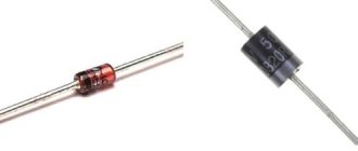
Appearance of varistors
What is a varistor
A varistor is a variable resistor made of semiconductor material that is capable of changing its electrical resistance depending on the voltage applied to it.
The operating principle of such an electronic component differs from a conventional resistor and potentiometer. A standard resistor has a constant resistance value at any time, regardless of the voltage in the circuit; a potentiometer allows you to change the resistance manually by turning the control knob. But the varistor has a nonlinear symmetrical current-voltage characteristic and its resistance completely depends on the voltage in the circuit.
Thanks to this property, varistors are widely and effectively used to protect electrical networks, machines and equipment, as well as radio-electronic components, boards and microcircuits, regardless of the type of voltage. They have a low manufacturing price, are reliable in use and can withstand high loads.
Varistors are used both in high-voltage installations up to 20 kV, and in low-voltage installations from 3 to 200 V as a voltage limiter. Moreover, they can operate both in networks with alternating and direct current. They are used to regulate and stabilize current and voltage, as well as in overvoltage protective devices. They are used in the design of surge protectors, power supplies, mobile phones, SPDs and other SPS.
I-V characteristics, equivalent circuit and varistor parameters
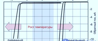
Typically, the current-voltage characteristics of varistors in the documentation are depicted on a logarithmic scale (Figure 4). At the same time, three characteristic areas can be noted on it: the area of leakage currents, the area of normal operation and the critical area. In the region of leakage currents, the characteristic has a linear form, and changes in voltage over a wide range have little effect on the current value. In the area of normal operation, the varistor opens: even a slight increase in voltage leads to a change in current by several orders of magnitude. The critical region characterizes the operation of the varistor at the limit of its capabilities.
Rice. 4. I-V characteristic of a varistor on a logarithmic scale
In order to reproduce the current-voltage characteristic of a varistor, you can use a simplified equivalent circuit (Figure 5). Roff has a high resistance (hundreds of MOhms) and characterizes the resistance of the varistor in low current mode (leakage current region). Roff depends quite strongly on temperature, so the temperature dependence of the leakage current is also clearly evident in this region. Rx – variable nonlinear resistance with a range of values 0…∞ Ohm. In the low current mode, the value of Rx can be neglected, but in the limiting mode this resistance shunts Roff and, in fact, determines the resistance of the varistor. Resistance Ron characterizes the resistance of the varistor at maximum currents in critical operating modes. Inductance L characterizes the parasitic inductance of the terminals. Parasitic capacitance C, along with parasitic inductance, determines the dynamic properties of varistors.
Rice. 5. Varistor equivalent circuit
The varistor's own dynamic properties turn out to be remarkable. For example, Figure 6 shows diagrams of the voltage pulse across the load without a varistor and with a varistor connected in parallel. The response speed of the varistor is so high that it reacts to an overvoltage with an edge of only 500 ps almost without delay. Unfortunately, in this case, the varistor is a ZnO plate connected directly to the coaxial line. In reality, output varistors have a huge parasitic inductance, which almost completely negates the real performance of ZnO.
Rice. 6. The varistor’s own performance is very high
Parasitic inductance introduces a delay, which results in a small initial overvoltage. The higher the pulse rise rate, the higher the overvoltage. Figure 7 demonstrates the increase in the varistor turn-on voltage with increasing pulse rise rate.
Rice. 7. The varistor switching voltage depends on the pulse shape
Varistors have significant parasitic capacitance, which negatively affects the operation of high-speed circuits. This is one of the reasons why varistors are not used to protect the signal lines of high-frequency interfaces. Obviously, the larger the diameter of the varistor disk, the greater its parasitic capacitance will be.
Another important parameter of varistors is leakage current. In many applications, such as measurement circuits, high leakage current can significantly degrade metrological performance. In addition, leakage current negatively affects the overall circuit consumption, which is critical for low-power devices.
When choosing varistors, it is necessary to take into account various temperature dependencies. We have already noted that in the area of leakage currents there is a strong dependence of the varistor resistance on temperature. In addition, you should remember about derating - reducing the maximum power dissipation with increasing ambient temperature (Figure 8).
Rice. 8. Reduction of maximum power dissipation with increasing temperature (derating)
One of the largest manufacturers of varistors is Littelfuse. Let's take a closer look at the range of varistors produced by this company.
Varistor properties
The main property of a varistor is its ability to reduce its own resistance depending on the voltage supplied to it. The higher the voltage is applied, the less resistance it begins to have. Varistors are connected to the electrical board in parallel with the protected device; in normal mode, the varistor operates at the rated voltage of the device it protects.
In normal mode, the electricity passing through the varistor is negligible, and therefore in such conditions it acts as an insulator.
If a sharp surge in electricity occurs, the varistor, due to its nonlinear characteristics, instantly reduces the value of its resistance to tenths of an ohm and removes the load from the general network, protecting it by radiating the excess energy received with heat. In such situations, a voltage of thousands of amperes can instantly pass through the varistor.
A varistor is a completely inertia-free device; as soon as the voltage in the network increases, its resistance immediately drops.
Characteristics
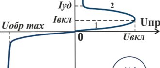
A varistor is a semiconductor resistor with a nonlinear current-voltage characteristic; its graph is shown in Figure 2.
Rice. 2. Typical current-voltage characteristics: A – varistor, B – conventional resistor
As can be seen from the graph, when the voltage across the semiconductor reaches a threshold value, the current increases sharply, which is caused by a decrease in resistance. This characteristic allows the varistor to be used as protection against short-term voltage surges.
Types of varistors
In appearance there are:
- film;
- in the form of tablets;
- core;
- disk.
Rod ones can be equipped with a moving contact. They will look like their name. In addition, there are low voltage, 3-200 V and high voltage 20 kV. For the former, the current fluctuates between 0.0001-1 A. This does not affect the designation according to the diagram in any way. In radio equipment, of course, low voltage is used.
To check the performance of the varistor, you need to pay attention to the appearance. It can be found at the input of the circuit (where power is supplied). Since a very large current passes through it - compared to the protected circuit - this, as a rule, affects its body (chips, burnt areas, darkening of the varnish coating). And also on the board itself: at the soldering site, the wiring tracks may peel off, causing the board to darken. In this case, it must be replaced.
However, even if there are no visible signs, the varistor may be faulty. To check its serviceability we will have to unsolder one of its pins, otherwise we will check the circuit itself. For continuity testing, a multimeter is usually used (although you can, of course, try a megger, you just need to take into account the voltage it creates so as not to burn the varistor). It is not difficult to ring it; it is connected to the contacts and its resistance is measured. We set the tester to the highest possible limit and make sure that the value is at least several hundred megohms, provided that the multimeter voltage does not exceed the response voltage of the varistor.
However, an infinitely large resistance, provided that the ohmmeter is quite powerful (if I can use this word), this also indicates a malfunction. When checking a semiconductor, it is necessary to remember that it is still a conductor and it must show resistance, otherwise we have a completely burnt part.
Checking a varistor - inspection, ohmmeter and multimeter
When this semiconductor device is triggered, significant heat is released and the varistor may burn out. This occurs when the peak voltage is high, when it is applied for a long time, or when a combination of both factors occurs.
There are several ways to check a varistor for further performance:
- Visual inspection. It should not be rejected, since many modern circuits are tightly packed, and a violation of the integrity of the outer shell of the device is easy to overlook. Any cracks, swelling or darkening on the varistor body indicate its failure.
- Dial using a multimeter. It is impossible to reliably check the varistor for serviceability with a multimeter directly on the board - you will have to solder at least one contact. It is important to measure in both directions by swapping the probes with each other. The multimeter mode selector must be set to the “diode check” cell; usually next to it there is a diode symbol and an acoustic indication icon. The entire varistor does not ring due to its significant resistance.
- Measurement with an ohmmeter or megaohmmeter. The ohmmeter should be set to the maximum value; in most household appliances this is 2 MegaOhms. On the scale they may be designated as 2000K or 2M. In theory, the measured resistance should be infinite; in practice, an ohmmeter can show the resistance value of a working varistor to be 1.5...2 MegaOhm. If you test a varistor with a megohmmeter, it is important to set the correct voltage value at its terminals. In powerful measuring instruments it can be higher than the threshold voltage for opening the varistor. Simply put, a semiconductor fuse can be burned during the testing process.
In practice, using a multimeter to diagnose the health of varistors is not so common, since in most cases an external examination is sufficient. When replacing a blown fuse, you should pay attention to the technical characteristics of its predecessor, otherwise the new varistor will fail much faster or will not perform its shunt function and damage the entire electronic unit.
Operating principle of varistors
In its normal state, a varistor has a very high resistance (according to various sources, from hundreds of millions of Ohms to billions of Ohms). It passes almost no current through itself. As soon as the voltage exceeds the permissible value, the device loses its resistance thousands, or even millions, of times. After the voltage normalizes, its resistance is restored. If a varistor is connected in parallel with an electrical appliance, then during a voltage surge the entire load will fall on it, and the devices will remain safe.
The principle of operation of a varistor, if explained in simple terms, boils down to the following. When there is a surge in the electrical network, it acts as a valve, passing through itself an electric current in such a volume as to reduce the potential to the required level. After the voltage has stabilized, this “valve” closes and our electrical circuit continues to operate as normal. This is the purpose of a varistor.
Features of the use of varistors
A typical varistor connection circuit has a number of features.
Varistor selection. As mentioned above, the varistor is selected based on the operating and classification voltages. However, it must be remembered that a varistor is not an ideal limiter. This means that the greater the interference power, the greater the current and voltage across the varistor. The interference directed to the protected section of the circuit will not be completely cut off, but only partially.
As a result, a significant overvoltage may be applied to the load for some time, and the load must be able to withstand it.
Figure 4 shows the case of strong interference. In the absence of a varistor, the LM2937-3.3 stabilizer chip, which has a maximum input voltage of 30 V, could be damaged. Varistor VRS0603SR090090N with an operating voltage of 9 V cut the noise voltage to 20 V. This overvoltage turned out to be applied to LM2937. Since the resulting noise turned out to be less than 30 V, the stabilizer was protected.
Rice. 4. Varistor connection diagram
Selecting a protective fuse. A varistor, being a protective element, itself requires protection. If the permissible power dissipation is exceeded, the varistor is destroyed. Very often, when destroyed, a varistor falls into pieces. This can lead to damage to surrounding elements, printed tracks and the PCB itself. To prevent this, input fuse FU1 is used (Figure 4), which will prevent the current from exceeding the maximum value.
You need to understand that the fuse current is selected less than the maximum pulse current of the varistor. The response time of the varistor is short, and the response time of the fuse is quite long, so the fuse must have time to warm up and operate before the varistor burns out.
On the other hand, from below, the fuse current value is limited by the load current. To get around this limitation, in addition to fuse FU1, fuse FU2 with a lower current value is included.
Response time requirements. In some cases, the load is protected from input noise and static discharges and is able to withstand voltage pulses of a certain duration. When choosing a varistor, you should pay attention to the response time. If the varistor does not have time to suppress the interference while its own load protection is operating, the load may be damaged. The response time of YAGEO varistors does not exceed 1 ns.
Features of series connection of varistors. This connection is used in cases where it is necessary to increase the total operating voltage of the varistors.
When varistors of the same type are connected in series, the power they absorb will be divided almost equally between them, despite the incomplete coincidence of the current-voltage characteristics. Indeed, the current flowing through the varistors is the same. The voltage, as mentioned above, will differ in accordance with the operating voltage accuracy by no more than ±20%, therefore the power will differ by no more than 40%.
Features of parallel connection of varistors. This inclusion is used quite rarely.
When connected in parallel, the same voltage will be applied to the varistors, but the currents will be different.
The difference in flowing currents can be estimated approximately. The difference in operating voltages, as shown above, is 40%. Previously, it was calculated that for the VRS0402SR55R220N, when the voltage changed by a factor of 4, the current changed by a factor of 100,000. Accordingly, when the voltage changes even by 0.4 times, the current can change hundreds of times, and the amount of power dissipated by parallel-connected varistors can change by tens.
With such differences in power, parallel connection makes virtually no sense.
Sometimes parallel connection of varistor columns (varistor chains) is used, but in this case varistors of the same batch are taken and selected according to the current-voltage characteristics.
Marking, main characteristics and parameters
Each varistor manufacturer labels its product in a certain way, so there are quite a large number of designation options and their interpretations. The most common Russian varistor is K275, and popular foreign-made components are 7n471k, kl472m and others.
We recommend reading: Pinout of different types of USB connectors: pinout of micro and mini usb, pinout features
The designation of the CNR-10d751k varistor can be deciphered as follows: CNR – metal oxide varistor; d – means that the component is disk-shaped; 10 is the diameter of the disk; 751 – response voltage for this device (calculation is done by multiplying the first two digits by 10 to the power equal to the third digit, that is, 75 multiplied by 10 to the first power, you get 750 V); k is the permissible deviation of the rated voltage, which is equal to 10% in any direction (l – 15%, M – 20%, P – 25%).
The main characteristics of varistors are the following parameters:
Classification voltage is the voltage at certain values of current flowing through the varistor (usually this value is 1 mA). This parameter is conditional and does not affect the device selection;
The maximum permissible voltage is the voltage range (rms or rms value) at which the varistor begins to reduce its resistance;
Maximum absorption energy is a characteristic showing the value of energy that the varistor dissipates and does not fail when exposed to a single pulse (measured in Joules);
Maximum pulse current – normalizes the rise time and duration of the current pulse (measured in Amperes);
Capacitance is a very important parameter, which is measured when the varistor is closed and at a given frequency (drops to zero if a large current is applied to the varistor);
Permissible deviation - deviation from the nominal potential difference in both directions (indicated as a percentage).
Response time is the period of time during which the varistor transitions from a closed state to an open state (usually several tens of nanoseconds).
Method for selecting and installing varistors
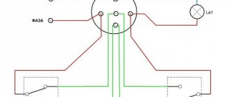
Varistors are installed in parallel with the protected electrical equipment. In the case of a three-phase load, with a star connection, they are connected in each phase between the phase and the ground, and with a delta connection, between the phases. The most preferable location for installing varistors is immediately after the switching device on the side of the protected load. A very convenient three-phase surge voltage limiter “Impulse-1” is produced, which is a device for fixing varistors on an electrical panel, containing devices placed in a housing - holders for three varistors, equipped with leads. This device allows you to easily implement protection schemes for three-phase loads connected in both star and delta, as well as protect up to three independent electrical installations powered by a single-phase network.
The choice of the type of varistor used and the determination of its classification voltage is carried out on the basis of an analysis of the operation of the varistor in two modes: in operating mode and in pulse mode.
1. Analysis of the operation of a varistor in operating mode consists of determining from Table 1 such a classification voltage for which the long-term maximum voltage at the load is closest to the table value, but does not exceed it. These tables are valid for varistors with maximum deviations of the classification voltage of no more than 10%. The maximum permissible long-term operating alternating voltage for foreign-made varistors is in most cases indicated as part of the marking.
2. Analysis of the operation of a varistor in pulse mode consists of calculating the maximum instantaneous energy using the formula:
where E is the maximum instantaneous energy in joules, P is the rated load power per phase (W), f is the frequency of alternating voltage (Hz), ? — Efficiency of the protected load. Such calculations are usually performed for loads of several kilowatts or more.
According to Table 2, select the type of varistor that provides energy dissipation, the value of which is calculated using the given formula. .
Table 1 In volts
classification voltage
| maximum permissible continuous AC voltage | maximum permissible continuous continuous voltage | classification voltage | maximum permissible continuous AC voltage | maximum permissible continuous continuous voltage | |
| 10 | 6 | 8 | 270 | 175 | 225 |
| 15 | 9 | 12 | 300 | 190 | 245 |
| 22 | 14 | 18 | 330 | 210 | 270 |
| 27 | 17 | 22 | 360 | 230 | 300 |
| 33 | 20 | 26 | 390 | 250 | 320 |
| 39 | 25 | 31 | 430 | 275 | 350 |
| 47 | 30 | 38 | 470 | 300 | 385 |
| 56 | 35 | 45 | 510 | 320 | 420 |
| 68 | 40 | 56 | 560 | 350 | 460 |
| 82 | 50 | 65 | 620 | 385 | 505 |
| 100 | 60 | 85 | 680 | 420 | 560 |
| 120 | 75 | 100 | 750 | 460 | 615 |
| 150 | 95 | 125 | 820 | 510 | 670 |
| 180 | 115 | 150 | 910 | 550 | 745 |
| 200 | 130 | 170 | 1000 | 625 | 825 |
| 220 | 140 | 180 | 1100 | 680 | 895 |
| 240 | 150 | 200 | 1200 | 750 | 1060 |
table 2
| Classification- | Maximum dissipation energy of varistors, J | |||||
| national nap- dressing up, B | CH2-2A | CH2-1a | CH2-1b | CH2-1v | VR-1-1 | VR-1-2 |
| 10 | — | — | — | — | 0.18 | — |
| 15 | 0.26 | — | ||||
| 22 | — | — | — | — | 0.56 | 0.23 |
| 27 | — | — | — | — | 0.64 | 0.26 |
| 33 | — | — | — | — | 0.71 | 0.30 |
| 39 | — | — | — | — | 1.3 | 0.47 |
| 47 | — | — | — | — | 1.6 | 0.56 |
| 56 | — | — | — | — | 1.9 | 0.66 |
| 68 | — | — | — | — | 2.3 | 0.76 |
| 82 | — | — | — | — | — | — |
| 100 | — | 17.0 | 10 | 2.7 | — | — |
| 120 | — | 25.2 | 12 | 3.0 | — | — |
| 150 | — | 31.5 | 15 | 3.8 | — | — |
| 180 | — | 37.8 | 18 | 4.5 | — | — |
| 200 | — | 42.0 | 20 | 5.0 | — | — |
| 220 | — | 46.2 | 22 | 5.5 | — | — |
| 240 | — | 50.4 | 25 | 6.0 | — | — |
| 270 | — | 56.7 | 28 | — | — | — |
| 300 | — | 63.0 | 31 | — | — | — |
| 330 | 104 | 69.3 | 34 | — | — | — |
| 360 | 115 | 75.6 | 37 | — | — | — |
| 390 | 125 | 81.9 | 40 | — | — | — |
| 430 | 138 | 90.3 | 43 | — | — | — |
| 470 | 152 | 98.7 | 47 | — | — | — |
| 510 | 168 | 107 | — | — | — | — |
| 560 | 187 | 118 | — | — | — | — |
| 620 | 207 | 130 | — | — | — | — |
| 680 | 227 | 143 | — | — | — | — |
| 750 | 248 | 158 | — | — | — | — |
| 820 | 280 | 172 | — | — | — | — |
| 910 | 312 | 191 | — | — | — | — |
| 1000 | 347 | 210 | — | — | — | — |
| 1100 | 385 | 233 | — | — | — | — |
| 1200 | 424 | 252 | — | — | — | — |
| 1300 | 463 | — | — | — | — | — |
| 1500 | 508 | — | — | — | — | — |
Example 1.
Determine the brand of varistors to protect the VASO16-34-24 electric motor when connecting the windings with a star in a 0.4 kV network.
Solution.
Because The windings are connected by a “star”, then each of them is under a voltage of 220V. If we take into account the normalized maximum permissible voltage deviation of 15%, then the maximum operating voltage will be 253 V. From Table 1 it is clear that the condition of clause 1 is satisfied by varistors with a classification voltage of 430 V.
From the passport data of the electric motor it is known that its power is 90 kW, efficiency is 91.8%, and cos? = 0.64. Let's calculate the value of the maximum instantaneous energy:
From Table 2 it can be seen that to protect this electric motor, a CH2-2 varistor (var. A, D) with a classification voltage of 430 V with a maximum dissipation power of 138 J can be used.
Example 2.
Determine the brand of varistor to protect the AO-315-UU3 electric motor when connecting the windings in a triangle.
Solution.
When connected in a triangle, each winding is energized at 380V. If the normalized maximum permissible voltage deviation is 15%, then the maximum continuous voltage will be 437 V. From Table 1 it is clear that condition p. 1 can only be satisfied when using varistors with a classification voltage of 750 V and higher.
Engine power 200 kW, efficiency 90%, cos? = 0.92. Let's calculate E:
From Table 2 it is clear that the CH2-2 750 V varistor already has a higher dissipation energy (248 J), which is why it should be used.
When using a two-phase load, the power value does not need to be divided by 3. Calculations show that already the CH2-2 varistor (var. A, D) in most cases provides protection for electrical equipment with a power of up to 30 kW. This means that for household electrical appliances it is practically sufficient to consider only point 1 and use small-sized varistors of the CH2-1 type or similar. In practice, there are cases when the value of the calculated operating current does not coincide with the experimental values. As a rule, this happens on alternating current, when the value of the reactive current is not taken into account, which can be calculated using known formulas. Thus, the reactive current of the varistor CH2-1 with a classification voltage of 430V (its nominal capacity is 600pF), when installed in a 220V household network, will be 0.04mA (which is comparable to the maximum operating current of 0.1mA).
Advantages and disadvantages of varistors
Important advantages of a nonlinear resistor (varistor) are its stable and reliable operation with high frequencies and heavy loads. It is used in many devices operating with voltages from 3 V to 20 kV, is relatively simple and cheap to produce and is effective in operation. Additional important benefits are:
- high response speed (nanoseconds);
- long service life;
- ability to monitor voltage drops (inertia-free method).
Despite the fact that this electronic component has many advantages, it also has disadvantages that affect its use in various systems. These include:
- low-frequency noise during operation;
- component aging (loss of parameters over time);
- high capacity: depends on the voltage and type of element, ranges from 70 to 3200 pF and affects the performance of the device;
- at maximum voltage values, power is not dissipated - it overheats significantly and fails at prolonged maximum voltage values.
Application of devices
Varistors are used to protect electronic devices from surge voltages whose amplitude exceeds the rated power supply. Thanks to the use of a semiconductor resistor in power supplies, it becomes possible to avoid many breakdowns that can damage the electronics. Varistors are also widely used in ballast circuits, which are used in lighting elements.
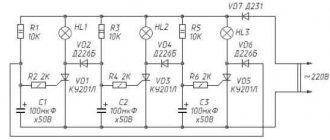
Some voltage and current stabilizers also use specialized semiconductor resistors, and varistor-dischargers with voltages of more than 20 kV are used to stabilize power in power lines. It can also be connected to the wiring diagram (diagram 1), protecting it from overloads and unacceptable amplitude values of current and voltage. When the wiring is overloaded, it heats up, which can lead to a fire.
You might be interested in the principle of operation, purpose and scope of application of triggers
Scheme 1 - Connecting a varistor for a 220V network.
Low-voltage varistors operate in a voltage range from 3 V to 200 V with a current from 0.1 to 1 A. They are used in various equipment and are installed mainly at the input or output of the power source. Their response time is less than 25 ns, however, this value is not enough for some devices and in this case additional protection circuits are used.
However, the technology for their manufacture does not stand still, since it has created a radio element with a response time of less than 0.5 ns. This semiconductor resistor is made using SMD technology. Disc-type designs have a higher response time. Multilayer varistors (CN) are reliable protection against static electricity, which can damage various electronics. An example use is the production of mobile phones that are susceptible to static discharge. This type of varistors are also widely used in the field of computer technology, as well as in highly sensitive equipment.
Diagnostics
To test this electronic device, special equipment called a tester is used. So, to carry out the test you will need a varistor, the principle of which is to change the resistance parameters, and a testing device. Before you start, you need to turn on the device and switch to resistance mode. Only then will the device meet all the necessary technical requirements, and the amount of resistance will be enormous.
Before starting testing, it is necessary to check the technical condition of the device. First of all, you should look at its appearance. The device should not show any cracks or signs that it has burned out. You should not inspect the device negligently, as any minor breakdown can lead to unpleasant circumstances.
Varistor selection
To choose the right varistor for a particular device, you need to know the characteristics of its power source: resistance and transient pulse power. The maximum permissible current value is determined, among other things, by the duration of its influence and the number of repetitions, therefore, if you install a varistor with a low peak current value, it will quickly fail. In short, to effectively protect the device it is necessary to choose a varistor with a voltage that has a small margin to the rated one.
Also, for the trouble-free operation of such an electronic component, the rate of dissipation of absorbed thermal energy and the ability to quickly return to a state of normal operation are very important.
Marking and selection of varistor
In practice, for example, when repairing an electronic device, you have to work with the varistor marking, usually it is made in the form:
20D 471K
What is it and how to understand it? The first characters in 20D are diameter. The larger and thicker it is, the more energy a varistor can dissipate. Next, 471 is the classification voltage.
Other additional symbols may be present, usually indicating the manufacturer or feature of the component.
Now let's figure out how to choose the right varistor so that it correctly performs its function. To select a component, you need to know in the circuit what voltage and type of current it will operate with. For example, it can be assumed that to protect devices operating in a 220V circuit, it is necessary to use a varistor with a classification voltage slightly higher (so that it operates when the nominal value is significantly exceeded), that is, 250-260V. This is fundamentally wrong.
The fact is that in AC circuits 220V is the effective value. If you don’t go into details, then the amplitude of the sinusoidal signal is at the root of 2 times greater than the effective value, that is, 1.41 times. As a result, the amplitude voltage in our sockets is 300-310 V.
240*1.1*1.41=372 V.
Where 1.1 is the safety factor.
With such calculations, the element will begin to operate when the effective voltage jumps more than 240 Volts, which means its classification voltage must be at least 370 Volts.
Below are typical ratings of varistors for AC networks with a voltage of:
- 100V (100~120)– 271k;
- 200V (180~220) – 431k;
- 240V (210~250) – 471k;
- 240V (240~265) – 511k.
How to check a varistor with a multimeter?
Checking a varistor using a tester or multimeter is a useful skill for radio amateurs and people who are handy and like to repair broken equipment themselves. This will be discussed in this article. What a varistor is intended for and what it does is described in sufficient detail in this article - an article about a varistor.
But let’s remember a little: a varistor is designed to protect variable or permanent circuits from overvoltage. It stands parallel to the circuit being protected and normally has a high resistance.
When the threshold voltage is reached, which depends on the brand of the varistor, its resistance decreases from very high to very small. A varistor absorbs this overvoltage and dissipates it into the atmosphere as heat.
Thus, it removes excess energy from the circuit, thereby protecting the circuit from failure.
Now let's start checking. Before using the tester, carefully inspect the radio element. It may have signs of burning, chips, or even break down.
Recommended reading: Stepper motor control
A careful inspection will save you from unnecessary work, although checking with a device does not take much effort, but still.
A varistor can also lose its properties over time, from external conditions and during the aging process - this is also worth paying attention to.
Measurements with a dial gauge
Such a device is considered analog. Its design uses an electromechanical head. It is a frame placed in a magnetic field. Depending on the current strength, the arrow in the frame deviates, stopping in a certain position. The range of needle deflection is graduated by numbers, according to which the resistance is calculated.
Before you start checking the varistor, you will need to set up the dial multimeter. To do this, it is calibrated. Its essence comes down to setting the zero position of the arrow by rotating a special handle while connecting the probes to each other.
To do this, the switch button selects the operating mode corresponding to the “Ω” icon, and the slide switch is set to the highest limit of resistance measurement by the tester. Most often it is designated as “x100”, which corresponds to megaohms. The resistance is measured from the power source (battery) installed in the device. Therefore, if you cannot set the needle to zero, the battery will need to be replaced.
When carrying out direct measurements, touch one terminal of the varistor with one probe of the tester, and touch the other with the other. As a result, three outcomes are possible:
- The arrow will deflect to zero or show resistance in the kilo-ohm region. A conclusion is made that the element is faulty (breakdown).
- The measurement result is within hundreds of megaohms. This reading indicates the serviceability of the varistor.
- When you touch the terminals of the radio element, the arrow does not react in any way. Possible reasons are as follows: the operating range of the device is not enough to measure the resistance value of the varistor, the device is faulty, the radio element is faulty (break).
Digital tester
Using a digital multimeter, checking the varistor for functionality will be a little easier than using an analog one. This is due to the fact that the digital tester has an LCD display in its design, which clearly displays the measured resistance.
The operation of this type of tester is based on an analog-to-digital converter, the operating principle of which is based on comparing the measured signal with a reference one. It should be noted that if, when you turn on the tester, a flashing battery icon appears on the screen, the battery will need to be replaced. The procedure for measuring the resistance of a varistor can be represented as follows:
The switch sets the maximum resistance measurement limit. Typically this limit is indicated by a number and a letter. If just numbers are written, then the unit of measurement is Ohm, the letter K after the number means kilo-ohm, the letter M means mega-ohm.
- The probes are fixed on two terminals of the varistor, and the reverse ends of the wires with plugs are inserted into the tester sockets marked Ω and COM. Since the polarity of the signal applied to the varistor does not matter, it does not matter which wire is connected to which terminal of the element. Although it is customary that a black cord is inserted into the COM connector.
- The device is turned on by pressing the ON/OFF button on the tester.
- If a unit is displayed on the indicator, this means that a small measurement limit has been selected.
- If numbers other than one are displayed on the screen, then this is the value of the measured resistance.
When interpreting the measurement result, the tolerance should also be taken into account. Each radio element has its own tolerance indicator. For example, if the tolerance is 10 percent and the internal resistance of the varistor is specified as 100 MΩ, then the results obtained should be between 90 and 110 MΩ. If the measured resistance of an element is found to be below or above this range, then it can be considered faulty.
Overview of varistors
The Littelfuse company produces a wide range of varistors (Figure 9). They can be divided into five segments (Table 4):
- MOV and MLV varistors for surface mounting ( SMD );
- MOV varistors with radial leads;
- industrial MOV varistors with high dissipation energy;
- specialized varistors;
- MOV varistors with additional thermal protection.
Rice. 9. Littelfuse varistors
Table 4. Overview of Littelfuse varistors
| Name | Operating voltage range AC, V | Operating voltage range DC, V | Peak current range, A | Peak energy range, J | Operating temperature range, °C | Number of protected lines | Execution | Disc size, mm |
| SMD MOV and MLV | ||||||||
| M.H.S. | – | 9…42 | – | – | -55…125 | 1 | SMD | – |
| MLE | – | 18 | – | – | ||||
| 0201 MLA | – | 5,5 | – | – | ||||
| M.L.A. | 2,5…107 | 3,5…120 | 4…500 | 0,02…2,5 | ||||
| MLA Automotive | 2,5…40 | 3,5…48 | 500 | 0,1…2,5 | ||||
| AUML | 18…48 | 1,5…25 | ||||||
| MLN | 4…14 | 5,5…18 | 30 | 0,05…0,10 | 4 | |||
| CH | 14…275 | 18…369 | 100..400 | 1,0…8,0 | 1 | |||
| SM7 | 50…510 | 68…675 | 1200 | 10…40 | -55…85 | |||
| SM20 | 20…320 | 26…420 | 6500 | 165 | ||||
| MOV varistors with radial leads | ||||||||
| LV UltraMOV | 11…95 | 14…127 | 500…10000 | 0,8…150 | -55…85 | 1 | Radial leads | 5, 7, 10, 14, 20 |
| UltraMOV | 130…625 | 170…825 | 1750…10000 | 12,5…400 | 7, 10, 14, 20 | |||
| UltraMOV® 25S | 115…750 | 150…970 | 22000 | 230…890 | 25 | |||
| C-III | 130…1000 | 3500…10000 | 40…530 | 10, 14, 20 | ||||
| L.A. | 130…1000 | 175…1200 | 1200…6500 | 11…360 | 7, 10, 14, 20 | |||
| ZA | 4…460 | 5,5…615 | 50…6500 | 0,1…52 | 5, 7, 10, 14, 20 | |||
| AUMOV | 14…42 | 16…50 | 400…5000 | 1,0…140 | -40…125 | 5, 7, 10, 14, 20 | ||
| HMOV | 11…625 | 14…825 | – | 4,2…490 | 10, 14, 20 | |||
| Industrial MOV Varistors with High Dissipation Energy | ||||||||
| BA/BB | 130…2800 | 175…3500 | 50000…70000 | 450…10000 | -55…85 | 1 | Screw or snap terminals | 60 |
| DA/DB | 130…750 | 175…970 | 40000 | 270…1050 | 40 | |||
| H.A. | 110…750 | 148…970 | 25000…40000 | 160…1050 | Radial leads | 32, 40 | ||
| HB34, HF34, HG34 | 110…750 | 148…970 | 40000 | 220…1050 | 34 | |||
| DHB34 | 110…750 | 148…970 | 40000 | 220…1050 | 34 | |||
| C.A. | 250…2800 | 330…3500 | 20000…70000 | 880…10000 | Leadless drive | 60 | ||
| Specialized MOV varistors | ||||||||
| M.A. | 9…264 | 13…365 | 40…100 | 0,06…1,7 | -55…85 | 1 | Axial leads | – |
| R.A. | 4…275 | 5,5…369 | 100…6500 | 0,4…160 | -55…125 | Radial leads | – | |
| High Reliability | 130…320 | 175…420 | 6000 | 50…120 | -55…85 | various | 7, 10, 14, 20 | |
| MOV varistors with thermal protection | ||||||||
| TMOV/iTMOV | 115…750 | 150…970 | 6000…10000 | 35…480 | -55…85 | 1 | Radial leads | 14, 20 |
| TMOV®25S | 115…750 | 150…970 | 20000 | 170…670 | 25 | |||
| TMOV®34S | 115…750 | 150…970 | 40000 | 280…1200 | 34 | |||
| SMOV®25S | 115…750 | 150…970 | 20000 | 170…670 | -45…75 | 25 | ||
| SMOV®34S | 115…750 | 150…970 | 40000 | 280…1200 | 34 | |||
| FBMOV | 115…750 | 150…970 | 40000 | 340…1340 | -55…85 | Bolted terminals | – | |
Surface Mount Varistors (SMD)
Traditional lead-out varistors cannot always be used in compact applications due to lack of available space. In addition, electronics manufacturers are trying to move away from pin-out mounting and use surface mounting as much as possible where possible. SMD varistors help solve this problem. Most SMD varistors use a multilayer MLV design, but the Littelfuse range also includes single-layer SMD varistors. SMD varistors produced by Littelfuse cover a wide range of operating voltages from units to hundreds of V and are capable of withstanding peak currents of up to several thousand A. Let's consider some lines from this segment (Figure 10).
Rice. 10. Examples of Littelfuse SMD varistors
MLA series – miniature multilayer SMD varistors for protecting DC and AC voltage circuits. Currently, the series includes more than fifty models with various standard sizes 0402/0603/0805/1206/1210, with an operating voltage range of 2.5...107 V AC and 3.5...120 V DC. The range of peak currents for representatives of the series turns out to be quite wide: 4...500 A (pulse 8/20 μs). MLA varistors are capable of operating in a wide range of operating temperatures -55...125°C.
MLA Automotive series is an analogue of MLA varistors for automotive applications. This series has AEQ-Q200 certification and unites about forty representatives with operating voltages of 2.5...107 V AC and 3.5...120 V DC. Models with standard sizes 0603/0805/1206/1210 are available to developers. The operating temperature range for these varistors is also -55...125°C. In addition to AEQ-Q200 qualification, MLA Automotive varistors are capable of withstanding high-power surges during load shedding, in accordance with SAE J1113 requirements.
AUML series is another series of MLV varistors for automotive applications that are AEQ-Q200 qualified. Unlike the series discussed above, AUML varistors have only five operating voltage options: 16, 18, 24, 48, 68 V. Among the advantages of varistors of this series, it is worth noting the compact standard sizes 1206/1210/1812/2220 and resistance to powerful impulse noise . In particular, AUML varistors are capable of withstanding more than 10 pulses, in accordance with SAE J1113.
CH series – compact MOV varistors for protecting AC and DC voltage circuits (Figure 9). These varistors are an excellent alternative to traditional radial lead varistors in applications with tight space constraints. The series includes a dozen and a half models with operating voltages 14...275 V AC and 18...369 V DC, peak current up to 600 A and miniature dimensions of only 5x8 mm. It is also worth noting the wide range of operating temperatures -55...125°C.
SM7 series is the highest voltage series of Littelfuse SMD varistors. Representatives of the series cover the operating voltage range of 50…510 V AC and 68…675 V DC. SM7 varistors have a plastic housing with dimensions of 11.4x8.3 mm. The case height is 3.6 mm or 6.0 mm depending on the model. The peak current for SM7 varistors reaches 1200 A (pulse 8/20 μs), and the operating temperature range is -40...85 ° C. Working with higher temperatures is also possible, but subject to derating.
MOV varistors with radial leads
This is the most representative group of varistors in the Littelfuse line, which combines traditional lead-out varistors with different characteristics. Let's look at some specific series.
UltraMOV series are real workhorses among varistors (Figure 11). They are used in a wide variety of applications, ranging from surge protectors and uninterruptible power supplies to power supplies, as well as a wide range of consumer devices. The series includes more than six dozen models with an operating voltage range of 130...625 V AC and 170...825 V DC, a disk diameter of 10/14/20 mm and a peak current of up to 10 kA (pulse 8/20 μs). There are two versions of varistors of this series. They differ from each other in the compound material and operating temperature range. Models filled with phenol-formaldehyde resin are capable of operating in the range of -55...125°C, and models filled with epoxy resin have an operating range of -55...85°C.
Rice. 11. Appearance of MOV varistors with radial leads
The LV UltraMOV series are MOV varistors designed primarily for the protection of 14...125 V DC circuits. Target applications for this series include LED lighting, audio and video devices, mobile phone chargers, alarm systems, telecommunications and industrial equipment and so on. The series includes more than sixty models with disk diameters of 5/7/10/14/20 mm and peak currents of up to 10 kA (pulse 8/20 μs). The operating temperature range of various models depends on the type of casting compound: -40...125°C (phenol-formaldehyde resin) or -40...85°C (epoxy resin).
LA series is a series with the widest range of covered operating voltages 130...1000 V AC and 175...1200 V DC. LA varistors have a classic disk shape with radial leads and a diameter of 7/10/14/20 mm. Among the distinctive features of the series are high dissipated energy up to 360 J and high peak current up to 6.5 kA. Many varistors in this series have two versions: version “A” with a standard limiting voltage value and version “B” with a reduced limiting voltage value. For example, models V130LA20AP and V130LA20BP have identical characteristics: operating voltage 130 V AC and 175 V DC, peak current 6500 A, disk diameter 20 mm. However, for the V130LA20AP the limiting voltage is 340 V, and for the V130LA20BP it is only 325 V. The operating temperature range for all models is -55...85°C.
ZA series is another series of MOV varistors designed primarily to protect DC voltage circuits of 5.5...615 V. ZA varistors are presented in traditional sizes 5/7/10/14/20 mm and have an operating temperature range of -55 …85°С.
AUMOV series is designed for automotive applications and is AEC-Q200 qualified. Representatives of the series cover a wide range of operating voltages 16...825 V DC and are able to withstand current pulses up to 5 kA. AUMOV varistors are available in traditional disk sizes of 5/7/10/14/20 mm and have different operating temperature ranges: -40...85°C (models with epoxy filling) or -40...125°C (models with silicone filling).
Industrial MOV varistors with high dissipation energy
This is a special group of varistors, which is designed to absorb heavy-duty interference with a peak current of up to 70 kA and peak energy of up to 10 kJ. The appearance of such varistors is very different from the appearance of conventional disk components (Figure 12). As a rule, high-power varistors have either terminal terminals or terminals with screw fastenings.
Rice. 12. Appearance of MOV varistors of the DA/DB series manufactured by Littelfuse
Varistors of the DA/DB are powerful MOV varistors manufactured by Littelfuse, designed to protect alternating voltage circuits 130...750 V AC and direct voltage circuits 175...970 V DC. DA varistors have screw terminals and DB varistors have 12.7mm terminals. The peak current for DA/DB varistors is 40 kA. The main application of this series is industrial equipment: electric motor drives, power supplies for the mining and oil and gas industries, and so on.
Specialized varistors Littelfuse
This group of varistors has specific features that are in demand in various applications. For example, members of the RA were developed for applications operating in environments with high vibrations. MA series is designed to protect against low-power interference and has an axial pin arrangement. High Reliability Varistors series provide maximum reliability and meet the requirements of military standards MIL-STD-19500, MIL-STD-202.
MOV varistors with additional thermal protection
After triggering, the varistor goes into voltage limiting mode. In this case, the interference power is dissipated directly on the varistor, which leads to its heating. If the interference energy is too high, the varistor may overheat and even explode. To solve this problem and increase the level of safety, varistors with a built-in thermal breaker were created (Figure 13).
Rice. 13. Varistors TMOV 25S with a built-in thermal breaker have three outputs at once
Figure 14 shows the structure and simplest circuit diagram for connecting a MOV varistor with a built-in thermal breaker using the TMOV25S as an example. An additional output is used to indicate the status of the thermal breaker.
Rice. 14. Structure and simplest circuit diagram for connecting the varistor TMOV 25S
The TMOV 25S series includes almost two dozen models with operating voltages 115...750 V AC, peak current 20 kA and operating temperature -55...85°C. The main applications for TMOV 25S varistors are power supplies, uninterruptible power supplies, surge protectors, etc.
The Littelfuse range of varistors includes a huge number of models, thanks to which the developer can find the optimal model for almost every specific application. However, such diversity complicates the selection process. Let's consider a step-by-step method for selecting the optimal varistor, proposed by Littelfuse [1].
How to find a varistor on the board?
According to the diagram above, it is clear that this element is located next to the fuse at the point where the power wires enter the board. This is usually a yellow or dark green disc.
In the photo the varistor is indicated by a red arrow. One might think that the varistor is a blue part covered with black soot, but on magnification one can see cracks on the varistor body, from which nearby parts are covered with soot. This is clearly visible on the reverse side, where the symbols are written. Even if they are not there, you can recognize a varistor, knowing that it is connected in parallel to the load or by the markings on its body.
VA1 is a varistor, and the blue part next to it is capacitor C70.
Do not confuse them, they are the same in shape, so be guided by the markings and symbols on the board.
After you have found a varistor, you need to unsolder it so that you can then install a new one in its place. To solder varistors, I usually use a gas soldering iron, because there is not always power supply at the repair site - at a facility under construction, on the roof, for example. It is also very convenient to use a desoldering pump - heat up the soldering area and remove the melted solder with a desoldering pump.
But for these purposes, tweezers or ordinary pliers are quite suitable - you need to grab the leg of the part and pull it out when the solder melts. If your solder does not melt well, then most likely it is high-temperature on the board - the so-called lead-free (you may have noticed the inscription PbF on my board - plumbum free). In this case, you need to either increase the temperature of the soldering iron tip or drop another lower temperature one on top, the soldering area will melt and the part can be removed. After this, we insert a new varistor and solder it.
We recommend reading: DIY FM antenna for a music center
For soldering, it is very convenient to use solder in the form of a wire that already has flux inside.
Also note that most boards are double-sided, so you need to solder the legs of the part on both sides of the board, since it often happens that the leg of the part acts as a jumper between tracks on different sides of the board.
After replacing the varistor, all that remains is to install a new fuse and install the board in place.
Typically, air conditioner circuit boards contain varistors for a voltage of 470 V, and fuses rated from 0.5 A to 5 A. Therefore, I recommend that you always have a small supply of these parts with you.
For those who need to repair the board by replacing the varistor, our service specialists will help, see prices here.
Designation on the diagram and options for connecting a varistor
On diagrams, a varistor is usually designated as a regular resistor, but with the addition of the letter U next to the slash. This feature indicates in the diagrams that this element has a dependence of resistance on voltage in the circuit. Also on the electrical diagram, this element is marked with two letters R and U with the addition of a serial number (RU1, RU2 ... etc.).
There are a large number of options for connecting varistors, but what is common to all methods is that this component is connected in parallel to the power circuit. Therefore, in the absence of dangerous values of voltage pulses, the current that flows through the varistor is small (due to large resistance values) and does not in any way affect the performance of the system. When an overvoltage occurs, the varistor changes the resistance to small values, the load is shunted, and the absorbed energy is dissipated into the surrounding space.
Operating principle
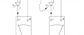
A varistor is a semiconductor device with a symmetrical nonlinear current-voltage characteristic. Based on its shape, we can conclude that the varistor operates in both alternating and direct current. Let's look at it in more detail.
In normal condition, the current through the varistor is extremely small; it is called leakage current. It can be considered as a dielectric component with a certain electrical capacitance and can be said to not allow current to pass through. But, at a certain voltage (in the picture it is + - 60 Volts) it begins to pass current.
In other words, the principle of operation of a varistor in protective circuits resembles a spark gap, only an arc discharge does not occur in a semiconductor device, but its internal resistance changes. As the resistance decreases, the current increases from a few microamps to hundreds or thousands of amperes.
Conventional graphical representation of a varistor in diagrams:
The designation of the element on the diagrams resembles a regular resistor, but crossed out diagonally by a line on which the letter U can be printed. To find this element on the board or in the circuit, pay attention to the labels; most often they are designated as RU or VA.
Read also: Diagnostics of the generator voltage regulator
Varistor appearance:
A varistor is installed in parallel with the circuit to protect it. Therefore, when the voltage pulse of the protected circuit occurs, the energy does not enter the device, but is dissipated in the form of heat on the varistor. If the pulse energy is too high, the varistor will burn out. But the concept will burn out, there are two options for development. Either the varistor will simply break into pieces, or its crystal will be destroyed and the electrodes will be short-circuited. This will cause the tracks and conductors to burn out, or the housing elements and other parts will catch fire.
To avoid this, a fuse is installed in front of the varistor in series with the entire circuit on the signal or supply wire. Then, in the event of a strong voltage pulse and long-term operation or burnout of the varistor, the fuse will also burn, breaking the circuit.
In short, what is such a component for? Its properties make it possible to protect the electrical circuit from harmful surges of voltage that can occur both on information lines and on electrical lines, for example, when switching powerful electrical appliances. We will discuss this issue a little below.
Use in everyday life
The characteristics of the element allow it to be used in devices associated with communication channels, various inputs for equipment, and the use of varistors for generators.
They are installed in surge protectors of special extension cords, as well as in other high-quality input models for protection. It is recommended to install the element in Chinese equipment to avoid quick breakdowns. To ensure the safety of the entire room, the varistor must be installed on a DIN rail.
Example of protection implementation
Figure 4 shows a fragment of a computer power supply circuit diagram, which clearly shows a typical varistor connection (highlighted in red).
Figure 4. Varistor in the ATX power supply
Judging by the figure, the circuit uses the TVR 10471K element, we use it as an example of decoding the markings:
- the first three letters indicate the type, in our case this is the TVR series;
- the next two digits indicate the diameter of the case in millimeters, respectively, our part has a diameter of 10 mm;
- Then there are three numbers that indicate the effective voltage for this element. It is deciphered as follows: XXY = XX*10y, in our case it is 47*101, that is, 470 volts;
- the last letter indicates the accuracy class, “K” corresponds to 10%.
You can also find simpler markings, for example, K275, in this case K is the accuracy class (10%), the next three digits indicate the magnitude of the effective voltage, that is, 275 volts.
Varistor marking
There are a huge number of varistors from different manufacturers, with different threshold operating voltages and designed for different currents. You can find out which varistor was installed by its marking. For example, marking varistors CNR :
CNR-07D390K , where:
- CNR-series, full name CeNtRa metal oxide varistors
- 07- diameter 7mm
- D – disk
- 390 – actuation voltage, calculated by multiplying the first two digits by 10 to the power equal to the third digit, that is, 39 multiplied by 10 to the zero power, you get 39 V, 271-270 V, etc.
- K – tolerance 10%, that is, the voltage spread can fluctuate from the nominal by 10% in any direction.
Varistor manufacturing
All this is explained by the device of the varistor. A varistor consists of a semiconductor and various bonding materials. A common combination is silicon carbide and epoxy resin. They are fused at high temperatures. Then, the surface of the varistor is coated with metal and the outputs are soldered.
Varistor design
The ability of a varistor to conduct high voltage through itself is provided by the material – silicon. When heated, silicon carbide crystals significantly reduce their resistance. And current can easily pass through them.
However, zinc oxide varistors are becoming increasingly common. They are easier to manufacture and can pass higher voltage pulses through them. The technique for their production is similar to the production of ceramic varistors.
Varistors come in various forms - cones, rods, disks. It all depends on the manufacturer.
Different forms of varistors