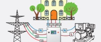
The proper and long-term operation of household appliances and electronics directly depends on the quality of energy consumed. For one reason or another, the current values of voltage and current in electrical networks do not always correspond to the specified values. To bring distorted parameters of electricity back to normal, stabilization systems installed at the input of the electrical network of a house or apartment, as well as in the circuits of electronic devices, are used. However, we should not forget that in electrical networks there is a phenomenon of pulse overvoltage, which lasts only a fraction of a second. The magnitude of the effective voltage can greatly exceed the rated voltage and irreversibly damage the equipment. The reason for the appearance of pulses can be the impact of a thunderstorm on electrical systems or switching processes in step-down transformer substations, as well as in installations with a high reactive load. You can protect electrical networks and equipment using surge protection devices. In this article we will look at how the SPD should be connected to the panel.
Causes of surge voltages
Household electrical appliances are made with semiconductors and microprocessors, which have poor insulation.
This technique can fail even with a small pulse voltage surge. Therefore, to protect electrical equipment from surge voltages, surge suppressors SPDs are used. There are several reasons for the occurrence of impulse noise. These are lightning strikes into power lines or metal structures that are located near electricity consumers. Lightning damage to lightning protection devices. Lightning discharges in clouds and nearby lightning strikes also cause electrical impulse noise in the power supply system.
Switching of large inductive and capacitive loads in energy-intensive enterprises, short circuit in the network. Even in enterprises, electromagnetic interference is created during the operation of powerful electrical installations.
What current pulses can occur in a domestic home network?
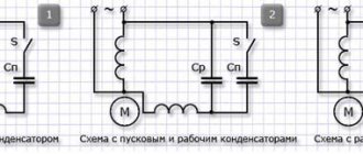
The nature of current flow through equipment is taken as the basis for the design of electrical appliances and is shown in the picture below.
An ideal sinusoid and the direct current rectified from it provide the nominal operating mode. It can be disrupted by an impulse coming from:
- lightning discharge;
- overvoltage of the electrical network in emergency modes.
The characteristics shown in the lower graphs are of a general nature. They change on a case-by-case basis. However, it should immediately be noted that the lightning impulse is much larger in magnitude and 17 times longer in time (350/20=17).
The power of lightning is much higher than the impulse of a normal network overvoltage and has increased destructive abilities compared to it.
Therefore, to eliminate the aftereffects of lightning, specialized pulse-type protection is used.
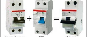
Stages of installation of surge protectors in a distribution board
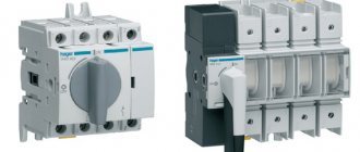
Let's consider a household case when a distribution switchboard with an arrester is assembled for an apartment or a private house, a panel of the appropriate volume is selected to accommodate a meter, an input circuit breaker and individual circuit breakers in groups, an SPD of the surge arrester type for installation on a DIN rail. When all elements with the appropriate technical characteristics and wires for connection have been purchased, you can begin installation:
- On the back wall inside the control panel, a sheet plate is fastened with screws, on which DIN rails and all other elements are installed. For ease of assembly, remove this plate and mount it on a table;
- First of all, the metering unit (meter) is attached to the plate, usually in the upper left part;
- On the right side of the meter, we attach a DIN rail of the appropriate size using metal screws or bolts to install the input circuit breaker and surge arrester on it;
- On the din river in the bottom row, RCDs and circuit breakers are installed in groups;
- At the very bottom there are contact blocks with screw clamps for connecting the neutral wires and separately the ground wires;
- If there is space left in the control panel, you can install a surface-mounted socket for open wiring.
The placement of elements on the plate is not strictly regulated by governing documents; individual elements can be placed on the right or left, depending on the conditions. Practice shows that it is easier to disconnect wires from above the input circuit breaker, so a meter, an input circuit breaker, and an arrester are placed in the upper part. In the second row there are RCDs and circuit breakers in groups, at the bottom there are blocks for grounding and neutral wires. After placing all the elements, you can start connecting the wires. To disconnect the entire distribution switchboard, a detailed consideration is required in a separate topic; let’s look at where and how the surge arrester is connected:
- From the lower terminal of the output of the input circuit breaker, the phase wire is connected to the input terminal of the upper part of the surge arrester;
- If the network is three-phase, the remaining phases are connected in the same way to the corresponding terminals;
- Output from the surge arrester, the terminals at the bottom are connected by wires to the block or grounding bus;
- The neutral wire is connected to the lower terminal with the sign “N”;
One of the options for placing elements and connecting an SPD in a distribution panel
When the switching of all elements is completed, the plate is inserted into the panel housing on the wall, secured with bolts, then the phases of the incoming cable are connected to the input of the input machine, and the grounding wire is connected to the appropriate block. The wires of various groups of the power supply network are connected to the output of the corresponding machines.
Please note that the surge arrester indicator in the initial state should be green; if it has completed its protective function, the indicator is red
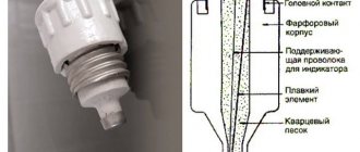
Purpose and principle of operation
The surge voltage limiter OIN-1 is needed to protect electrical networks with a voltage of 380/220V. These are standard voltages for powering electrical networks. Voltage surges can occur as a result of lightning strikes. Because of them, a potential difference arises in the ground. In addition to them, switching bursts in the network are distinguished. They occur when powerful electrical appliances are turned on or off or a group start of consumers in an electrical installation. Switching pulses can occur when starting powerful electric motors or group starting of pumping stations, as well as when turning on capacitor units.
How does the limiter work? Varistors are installed inside OIN-1. According to the principle of operation, varistors resemble arresters that were used previously. Therefore, the limiter is installed parallel to the protected circuit. If the voltage in the network exceeds the permissible (classification) voltage of the varistor, it begins to short-circuit the wires, thus diverting the danger from electrical appliances connected after it.
Kinds
Depending on the device and operating principle, SPDs are divided into several types.
Switching protective devices
Also called spark gaps. The operating principle of the spark gap is based on the use of the spark gap phenomenon. The design has an air gap in the jumper that connects each of the power lines to the ground loop. The circuit in the jumper is open at rated voltage. If a lightning discharge occurs due to overvoltage in the power line, an air gap breakdown will occur, the circuit between the phase and the ground will be closed, and the high voltage pulse will be directly grounded. The design of the valve arrester in the circuit with the spark gap provides a resistor across which the high voltage pulses are suppressed. In most cases, arresters are used in high-voltage networks.
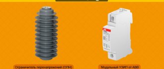
SPD-arrester
Network surge suppressors (OSV)
These devices replace outdated, bulky arresters. To understand the principle of operation of the limiter, it is necessary to consider the characteristics of a nonlinear resistor, since the principle of operation of the arrester is based on its current-voltage function. Varistors are used as nonlinear resistors in these devices. The main material for the manufacture of varistors is zinc oxide. When mixed with other metal oxides, a component is formed that forms a pn junction with current-voltage characteristics. When the network voltage corresponds to the nominal parameter, the current in the varistor circuit is close to zero. When an overvoltage occurs in a pn junction, the current increases sharply, causing the voltage to drop to the nominal value. After standardizing the network parameters, the varistor returns to non-conducting mode without affecting the operation of the device.
You may be interested in: Choosing an electric meter
Limiters
Combined SPDs
Combined devices operate on the principle of a spark gap, but also have a resistor in their design. With this design, the voltage is not only grounded, but also stabilized in parallel in the main circuit.
Classes
Such devices can be divided into several categories:
- Class I. Designed to prevent direct lightning exposure. These devices must be equipped with input distribution equipment (ADS) for administrative and industrial buildings and residential apartment buildings.
- Class II. They provide protection to the distribution network against overvoltages caused by the switching process and act as secondary protection to prevent the effects of lightning strikes. They are installed and connected to the network in the panel.
- Class III. They are used to protect equipment from voltage surges caused by residual surges and asymmetrical voltage distribution between phase and neutral lines. Such devices can also operate in high-frequency interference filter mode. The most convenient thing for private houses or apartments is that they are connected and installed directly by consumers. It is especially popular to manufacture the device as a module that can be quickly mounted on a DIN rail, or in a wall outlet or plug configuration.
Diagram of the VC-122 series device
The surge and interference protection device of this series is suitable for step-down transformers. The model is also actively used in RS series shields
First of all, it is important to note that the model uses a high-voltage modulator. Its output conductivity parameter is 2 μ
The model is suitable for RS19 shields. In this case, the modulator is connected through the plate.
Filters are only allowed to be used as a pass-through type. If we look at the RS20 series shields, they have a damper. The expander for connection is used magnetic type
It is also important to note that 200 V step-down transformers cannot be used
Details Published: September 29, 2015
Here I present several typical connection diagrams for surge protection devices (SPDs). Below you will find single-phase and three-phase diagrams for different grounding systems: TN-C, TN-S and TN-CS. They are clear and understandable for the common man.
Today there are a large number of SPD manufacturers. The devices themselves come in different models, characteristics and designs. Therefore, before installing it, be sure to study the passport and connection diagram. In principle, the essence of connection for all SPDs is the same, but I still recommend reading the instructions first.
All laid out diagrams contain RCDs and group circuit breakers. I indicated them for clarity and completeness of the distribution panel. This “filling” of your shield may be completely different.
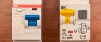
SPD connection diagram in a single-phase network of the TN-S grounding system.
This diagram shows an SPD of the Easy9 series from Schneider Electric. The following conductors are connected to it: phase, zero working and zero protective. Here it is installed immediately after the introductory machine. All contacts on any SPD are marked. Therefore, where to connect the “phase” and where to connect the “zero” can be easily determined. A green flag on the case indicates a working condition, and a red flag indicates a faulty cassette.
The presented device belongs to class 2. It alone is not capable of protecting against a direct lightning strike. Competent selection of SPDs is a complex and separate topic.
It is also recommended to protect SPD devices with fuses.
I think everything is clear here.
Below is a similar diagram for connecting an SPD, but without an electric meter and using a common RCD.
SPD connection diagram in a three-phase network of the TN-S grounding system.
The diagram also shows an SPD manufactured by Schneider Electric of the Easy9 series, but for a 3-phase network. The figure shows a 4-pole device with a neutral working conductor connected.
There is also a 3-pole SPD of the same series. It is used in the TN-C grounding system. It does not have a contact for connecting the neutral working conductor.
SPD connection diagram in a three-phase network of the TN-C grounding system.
The SPD from IEK is shown here. This diagram is a regular input panel for a private house. It consists of an input circuit breaker, an electric meter, an SPD and a general fire protection RCD. The diagram also shows the transition from the TN-C to TN-CS grounding system, which is required by modern standards.
The first picture shows a 4-pole input circuit breaker, and the second picture shows a 3-pole one.
There is no more permanent connection than a temporary twist!
This is where you need to be very careful. Incorrect selection of a circuit breaker according to its rating can lead to a fire in the wiring or the machine will trip five times.
A circuit breaker has tripped in your apartment panel. As a result, some part of the apartment lost power. Almost everyone has found themselves in this situation. What are your next steps?
Light bulbs have burned out, are burning out and will continue to burn out, otherwise it is not profitable to produce them. Just think about it: a factory produced one light bulb, a person bought it, screwed it in at home and it works as expected.
Cables and wires play one of the most important roles in powering your home. An incorrect choice of cross-section can lead to overheating of the insulation, its breakdown, short circuit and serious problems.
Friends, respect the work of others and when copying materials, please put an open link to the source sam-sebe-electric.ru, otherwise I will turn off the light. |
The difference between a three-phase relay and a single-phase one
Devices designed for connection to a three-phase network have expanded functionality compared to single-phase devices. When protecting 3-phase electrical equipment, in addition to monitoring the supply voltage level, the following parameters are additionally monitored:
- symmetry of the three-phase power system;
- open circuit (break) of the neutral wire, in which line voltages remain normal and phase voltages are absent;
- phase rotation order;
- Some types of relays have a function for monitoring the frequency of the supply network.
Symmetry control is carried out by constantly comparing the vector difference of phase voltages.
The presence of a symmetry factor is important for the proper operation of 3-phase equipment - electric motors, transformers. An extreme case of asymmetrical mode occurs when one or two supply phases are broken
Operation of motors in a 380 volt network in open-phase mode is not allowed, as this leads to damage to their windings. StabExpert.ru reminds that the danger of such a regime is aggravated by the fact that in this case current protections usually do not work.
Violation of the phase sequence entails reverse (that is, directed in the opposite direction) rotation of electric motors, which leads, at a minimum, to incorrect operation of the mechanisms, disruption of the technological process, and even damage to installations. This type of eating disorder can occur in two cases:
- incorrect connection of phases in the distribution cabinet or at the electric motor terminals, carried out by the consumer himself;
- an error by network enterprise personnel, which can occur, for example, when connecting cable inputs in substation switchgears after repairs.
Therefore, install an appropriate stabilizer that will monitor the “skew” of parameters, or a three-phase voltage relay with phase control (review of models below). We have a separate article on how to choose a 380V voltage stabilizer for your home.
As for the frequency of the power supply network, there are mainly two reasons for its change:
- 1. A decrease in frequency can be observed in regions with a shortage of generated active power, in other words, when the total load of consumers exceeds the power generated by stations. In some regions, this violation is systemic and long-lasting.
- 2. An increase in frequency is observed less frequently, for example, during short-term “surges” of power, which usually occur when powerful high-voltage power lines are turned off. At these moments, an excess of power generated by power plant generators appears, which is very quickly eliminated by the action of system automation, so the consumer is not particularly worried.
Whether to disconnect from the mains when the frequency changes is up to the consumer to decide; it depends on how critical his equipment is to such changes.
The voltage relay control circuits must be permanently connected to the mains supply and when the load is disconnected, they must not be turned off along with it. This is understandable, because if you connect the control circuits after the contacts of the executive relay, then at the first disconnection the control will be lost and automatic reconnection will not occur.
Connection of SPD according to degree of protection
Each device with individual protective properties has its own SPD connection diagram.
- 1st degree devices are installed in panels of the RV series. Direct connection is made using a transceiver. The average output voltage is 14 volts. Conductivity may vary according to the type of resistors used. An amplifier is used together with them. The threshold conductivity is on average 4.5 microns. Before starting the connection, you need to check the total resistance of the circuit. It should be 50 ohms. These devices are not suitable for other types of shields due to their high current conductivity.
- Devices of the 2nd degree are used in the PP series panel. Here, the SPD connection diagram dispenses with transceivers and all connections are made only with conductors. Before connecting, the parameters of the output voltage on the stabilizer are also checked, which is approximately 13 volts. During operation, two-pin extenders are used. Insulators are installed in the PP20 panels, and the SPD is connected via a grid triode with an operational amplifier. PP21 panels are equipped with integrated rectifiers involved in current conversion.
- SPDs of the 3rd degree are designed for installation in panels equipped with a feed-through dinistor. A damper is used to connect equipment. The connecting contacts have a copper lining. The total circuit resistance does not exceed 40 Ohms. In PP19 panels, the thyristor is installed together with the amplifier. Some modifications use capacitor resistors. It is possible to connect the device together with an adapter.
How to determine the type of grounding system
To determine the type of grounding system, you need to consider the PEN conductors, that is, how they are separated. If everything is ready, the wiring is similar to the TN-CS system. In this case, for a three-phase circuit, five main wires come from the main distribution panel of the house, but for a single-phase circuit, only three wires are used. PEN conductors are divided into two components: PE and N.
Note! If it is not split, the wiring will work according to the TN-C system, with 4 wires from the three-phase system and 2 wires from the single-phase system coming from the distribution panel.
Based on the principles described, the type of grounding system can be easily determined. In all cases when the TN-C system is used in private homes, it is recommended to transfer it to the TN-CS scheme, which is more promising and safer.
You might be interested in SPD installation - connection diagrams, installation rules
How to calculate a grounding system
SPD protection classes
The classification of these protective devices is made in accordance with GOST R 51992-20111.
GOST defines the following classes of these devices:
- 1st class or "B". These devices protect against the direct effects of lightning when lightning strikes enter the system. They also neutralize atmospheric and communication overvoltages. For installation, a connection diagram is used from the input to the facility where the main switchboard and ASU are installed. Class 1 devices are primarily used for buildings located separately in open space or connected to overhead power lines. Other connection factors include neighboring houses equipped with lightning rods or tall trees located nearby. The value of the rated discharge current is in the range of 30-60 kA.
- 2nd class or "C". These devices neutralize the remnants of atmospheric and switching overvoltages that have overcome class 1 protection. The installation location, including for UZM, is the usual input panels of an apartment, house or office. The discharge current rating is 20-40 kA.
- 3rd grade or "D". Protect electronic equipment from residual high voltages and high-frequency interference missed by class 2 protection. An example is a surge protector to which a computer is connected. Withstands discharge current from 5 to 10 kA. Using devices of all three classes, single-line multi-stage protection is created.
SPD classes
Class I (B). Devices belonging to this class protect against direct lightning strikes into the lightning protection system of a building or overhead power grids. Installation of these devices is carried out directly in the ASU or main switchboard where the cable enters the building. These devices are designed for a discharge current of about 30-60 kiloamperes.
Second class (C). These devices are designed to protect power distribution networks of objects from switching interference. They are capable of functioning as a second protective stage against lightning strikes. They are installed in the switchboard, and their discharge current is rated at 20-40 kiloamperes.
Class III (D). Blocks, which are protective devices of this class, are installed directly in front of the consumer device. Such devices can be very different in design (socket, plug, separately mounted module, or wall-mounted device). Their discharge current does not exceed 5-10 kA.
The main element in the construction of such devices was a varistor or arrester. In addition, these devices include an indicator device that can indicate that the SPD has failed.
One of the negative indicators of these “defenders” is that they heat up when activated, which is the reason that they need time to cool down, and this greatly reduces the selectivity of the device.
Such a device is mounted on a DIN rail. A varistor that has failed can be easily changed by removing the latter from the housing.
To achieve good quality consumer protection from unnecessary influences, it is necessary to provide buildings with effective grounding systems and potential equalization. For this purpose, a grounding system of the TN-C or TN-CS type is used, which has separation of the neutral and protection conductors.
Then protection devices are installed, the distance between which (from one class to another) should not be less than 10 meters along the power cable. Only if such conditions are met can the correct operation of the protective devices be ensured.
On overhead lines and in input panels on poles, systems based on arresters and fuse-links work best.
The main switchboards of buildings are well protected by SPDs of the first and second class, based on varistors, and floor switchboards are equipped with systems of the third class. As additional protection, sockets are equipped with systems in the form of inserts and various extension cords.
Finally, I would like to note that devices of this type significantly reduce the percentage of consumer failures and human injury from high voltage, although they are not able to fully provide one hundred percent protection. Therefore, during a thunderstorm, you should, if possible, disconnect the most important consumers from the power supply.
Write comments, additions to the article, maybe I missed something. Check out the site map. I will be glad if you find anything else useful on my site. All the best.
Power limiters OM-630-2
Discount!
Price: 3560.00 3381.00 UAH.
Warranty: 18 months
(Poland)
Additional images
Description
Purpose: The Ohm 630-2 power limiter controls the power consumed in a three-phase network. If the set value is exceeded, the consumer will be disconnected (works with current transformers over 50 kW.)
Operating principle: The Om-630-2 device continuously, phase by phase, measures current and voltage, guided by a given operating algorithm. In the event that the indicators are exceeded, using a power contactor, the limiter will turn off the load for a certain time interval.
Installation: attach the OM 630-2 limiter to the DIN rail in the shield. The settings are set by the regulator on the front of the device.
Note: This power limiter can be configured with a voltage relay function: protection against voltage exceeding 260 V and voltage falling below 160 V (discussed when ordering). In addition, there is also a similar relay model OM-630 (control up to 50 kW).
Characteristics
| Parameter | Meaning |
| Supply voltage: | 3x(150-380 V~) + N |
| Controllable power range: | 5 - 50 kW |
| Power setting resolution, roughly: | 5 kW |
| Power setting resolution, exactly: | 0.5 kW |
| Overpower shutdown delay | from 1 to 240 s |
| Load restart delay: | from 2 to 3600 s |
| Shutdown delay when voltage drops below 160 V: | 5 s |
| Shutdown delay when voltage rises above 260 V: | 0.1 s |
| Overcurrent shutdown delay: | 0.1 s |
| Maximum load current: | 2x8 A |
| Voltage measurement error in the range 50 - 300 V: | no more than 2% |
| Current measurement error in the range 3 - 100 A: | no more than 3% |
| Diameter of through holes measured. chains: | d=12.5 mm |
| Operating temperature range: | from -25°С to +50°С |
| Galvanic isolation: | 6 modules type S (105 mm) |
| Installation: | on DIN rail 35 mm |
Important Note
We looked at why OIN-1 is needed and how to install it. But it is imperative to add a note from the official documentation:
We are talking about connecting the machine to the break in the supply wire in front of the limiter. This is necessary in order to break the circuits in the event of a short circuit in the pulse limiter and prevent the negative consequences of the event.
Finally, we recommend watching a video that clearly explains how to connect a surge voltage limiter to the network:
This is where we finish the description of the characteristics and rules for connecting OIN-1. We hope that the prepared review was useful and interesting for you!
You probably don't know:
Technical characteristics of SPD
These include:
The surge waveform is standardized for the following cases:
- direct lightning strike – 10/350 µs;
- exposure to indirect lightning – 8/20 µs.
Pulse shape 8/20 µsPulse shape 10/350 µs
According to their intended purpose, according to the IEC standard, SPDs are divided into types 1-3; according to GOST R 51992-2002, they are divided into test classes (I – III). The correspondence and purpose of these characteristics are indicated in the table.
| Types according to IEC 61643 | Classes according to GOST R 51992-2002 | Purpose | Installation location |
| 1 | I | To limit overvoltages from direct lightning strikes | At the entrance to the building, in the main distribution board |
| 2 | II | To limit overvoltages from distant lightning strikes and switching overvoltages | On entries where there is no danger of direct impacts |
| 1+2 | I+II | The characteristics of SPD types 1 and 2 are combined | Same as type 1 or 2 |
| 3 | III | To protect sensitive consumers. Have the lowest level of protective voltage | For direct installation at consumers |
According to their design, SPDs are produced with a different number of poles: from one to four.
DTR 1/6/1500 SPD for telecommunication and signaling systems (information systems)
Surge and interference protection device (SPD) DTR 1/6/1500. It is used in distribution networks within 0v-2 lightning protection zones (in accordance with the “Instructions for the installation of lightning protection of buildings, structures and industrial communications” SO-153-34.21.122-2003 and GOST R IEC 62305-1).
1. Purpose
The DTR 1/6/1500 device is designed to protect the equipment of distributed networks of industrial automation equipment (process control systems, ASKUE, etc.), digital data transmission interfaces (recommended for a two-wire RS-485 interface with a data transfer rate of up to 1 Mb/s), signal lines of control and measurement systems, as well as to protect secondary power circuits and other things from surge voltages (lightning, electrostatic discharges).
2. Specifications
| Type | DTR 1/6/1500 | ||
| Number of protected pairs | 1 | ||
| Temperature range | extended | ||
| Rated operating voltage, DC/AC | Uо | 6V / 4V | |
| Maximum continuous operating voltage, DC/AC | Uс | 7V / 5V | |
| Rated load current | IL | 250 mA | |
| Type of current | constant / variable 50Hz | ||
| (D1) Pulse current (10/350) | Iimp | 2/4; 2.4/PE; 2+4/PE | 2.5kA |
| (C2) Nominal discharge current (8/20) | Iв | 2/4; 2.4/PE; 2+4/PE | 20kA |
| Protection voltage level at I=1kF (8/20) | Uр | 2/4 | < 18kA |
| Protection voltage level at 1 kV/µs, (SZ) | Uр | 2/4 | < 10V |
| Max. pulse power dissipation | Robr | 1500 W | |
| Response time | t,A | < 1ns | |
| Data transfer rate, no more | 1Mbit/s | ||
| Introduced resistance into the conductor | 2.2 ohm | ||
| Injection capacity | WITH | 1.5 pF | |
| Type of climatic modification according to GOST 15150-69 | U2.1. | ||
| Working temperature | -40…+80 C | ||
| Installation | DIN rail 35 mm | ||
| Connected wire cross-section | 0.25-4.0 mm.2 | ||
| Screw terminal tightening torque | Nm | 0,5 | |
| Degree of housing protection in accordance with GOST 14254-2015 | IP20 | ||
| Housing material | Polyamide PA6 | ||
| Case color | grey | ||
| Category in accordance with GOST IEC 61643-21 | C2, C3, D1 | ||
| Weight | 70 | ||
| Catalog code | 400 617 |
3. Design and device
The first stage is made on a gas-filled spark gap, the second on TVS diodes with maximum pulsed power dissipation Robr. = 1500 W. The stages are separated by resistors.
The DTR 1/6/1500 device is housed in a plastic case with protection class IP20. The device is mounted at 35 mm. DIN rail using a special latch on the back of the case. The device body contains terminals for connecting the conductors of the protected line.
4. Installation instructions
The DTR 1/6/1500 device is recommended to be installed near the protected equipment.
When designing cable routes to the protected equipment, it is necessary to avoid joint parallel runs of protected and unprotected sections of the cable, as well as the protected cable and grounding conductor.
The DTR 1/6/1500 device is connected to the grounding bus using a conductor with a cross-section of 1.5 - 2.5 mm.2. The grounding conductor should be as short as possible.
Connection of the device is carried out only by specially trained qualified personnel.
5. Operating instructions
The surge protection device type DTR 1/6/1500 is a multiple-action device and is designed to pass large pulse currents during a direct lightning strike into the external lightning protection system of the facility. At the same time, one cannot ignore the possibility of its damage due to intense, frequently repeated lightning strikes on the protected object or in the immediate vicinity of it. In this regard, it is necessary to periodically check the condition of the SPD.
The surge protection device is used in the assembly of metering panels, control panels, metering panels included in the main distribution, distribution and power panels, control and automation cabinets.
Price list available at the warehouse of MES-Electro LLC
Surge protection devices SPD: application, connection diagram, operating principle
During a thunderstorm, impulse noise often occurs in the network. They can also be observed when a transformer breaks down. To protect electrical equipment in the house, special SPD devices are used. They are installed in shields of different configurations.
The difference between the modifications lies in the parameters of the output voltage, threshold frequency and conductivity. The standard model consists of a block and contacts. Resistors are installed in various types. The modulator in the devices is connected to the transceiver. This element contains conductors and a triode. In order to learn more about SPDs, you should consider the operating principle of the model.
Information about the company
ASBERG AS, LLC is one of the largest distributors of ABB, Schneider Electric, Klemsan, ABL SURSUM, LSIS. The company cooperates with such significant players in the electrical engineering and industrial automation market as Rittal, Legrand, Finder, DKC, OWEN, MOXA and many others, providing direct supplies of their products. ASberg AS is engaged in the distribution of low-voltage electrical equipment, as well as the supply, design, installation and maintenance of low-voltage and medium-voltage complete devices, equipment and transformer substations. Contacts and addresses · Documents · Publications · Videos
- https://domikelectrica.ru/ustanovka-uzip-sxemy-podklyucheniya-pravila-montazha/
- https://electrikblog.ru/uzip-dlya-chastnogo-doma-skhemy-podklyucheniya/
- https://www.elec.ru/articles/kak-zashitit-dom-ot-impulsnyh-perenapryazhenij/
Devices of the TESSLA D32 series
Devices of this series are manufactured with pass-through modulators. Their contacts are of the movable type. For PP20 series shields, this device is often used. The modulator is connected via an expander. It is most often used with a converter. To solve problems with increasing frequency, a tetrode is installed.
If we consider the shields of the PP10 series, then they have a kenotron. The specified element is installed on two or three outputs. In the first option, the device modulator is connected via a damper. Its output conductivity parameter is 3.3 microns. The total resistance in the circuit is 30 ohms. If we consider the second option, then the SPD will require a dinistor.
Regulatory basis for the use of SPDs
What is an SPD? The main Russian document defining what an SPD is is GOST R 51992-2002 “Devices for protection against surges in low-voltage power distribution systems.”
According to this GOST, “Device for surge protection (SPD): a device that is designed to limit transient overvoltages and drain current pulses. This device contains at least one nonlinear element." The standard applies to devices for protecting electrical networks and electrical equipment under direct or indirect influence of lightning or other transient overvoltages. These devices are designed for connection to AC power circuits with a frequency of 50-60 Hz for a rated voltage of up to 1000V (rms value) or 1500V DC.
Depending on the test class, SPDs are divided into 3 types.
Class I tests are designed to simulate partially directed lightning current pulses. SPDs subjected to such tests are recommended for installation on linear inputs into buildings protected by lightning protection systems, as well as for air supply input. A characteristic feature of this class is the pulsed current test Iimp with a waveform of 10/350 µs (1). The most important parameter characterizing the SPD is the protection voltage level Up, which is measured at In. This is “a parameter characterizing the SPD in terms of limiting the voltage at its terminals, which is selected from among the preferred values.” Its value is always higher than the residual voltage Ures, i.e. peak value appearing at the terminals of the SPD due to the passage of a discharge current of a given amplitude. Up should not exceed the resistance of electrical equipment to impulse voltage, defined in GOST R 50571.19-2000. Therefore, it is accepted that for a class 1 SPD Up does not exceed 4 kV.
Standard test pulse
Class II tests are designed to simulate a pulse induced in conductors by an electromagnetic field. SPDs subjected to such tests (2nd class SPDs) are intended for installation after 1st class SPDs in intermediate cabinets, or in the incoming cabinet, if there is no likelihood of part of the direct lightning current entering the power supply system. Tests are carried out with the rated discharge current In and the maximum discharge current Imax. Both pulses have a waveform of 8/20 µs, but different amplitudes. In this case, Imax > In. The SPD must withstand the In pulse multiple times, provided that it cools to room temperature in the interval between pulses. Typically, the number of withstand pulses is from 5 to 15 (according to GOST, the number is not established and is determined by the manufacturer, according to IEC - 15 pulses). The SPD must withstand the Imax pulse once, while its further operation in accordance with the declared parameters is not guaranteed (but possible). The protection voltage level Up for class 2 devices should not exceed 2.5 kV.
Class III tests also simulate an induced pulse, but are tested with a combined 1.2/50 µs voltage and 8/20 µs current waveform. In this case, the parameters indicate the open circuit voltage Uoc and the rated In and maximum Imax currents. The protection voltage level Up for class 3 should not exceed 1.5 kV. This is the level that equipment must withstand, even if it has not been tested for resistance to microsecond pulse overvoltages. Therefore, it is recommended to use these devices in close proximity to the protected equipment (preferably no further than 5-7 meters, but in general, the closer, the better).
A few more important parameters that you need to know to select an SPD.
The maximum long-term operating voltage Uc is the effective value of alternating or direct current, which is continuously supplied to the terminals of the SPD. It is equal to the rated voltage, taking into account the possible overestimation of voltage under various abnormal network operating conditions.
Rated load current IL is the maximum continuous alternating (rms value) or direct current that can be supplied to the load protected by the SPD. This parameter is important for SPDs connected to the network in series with the protected equipment. Since most SPDs are connected in parallel to the circuit, this parameter is not indicated.
Fuse or switch?
The fuse link has negligible inductance. There is no voltage drop across it, which means that if something happens, the damaged SPD will turn off as expected.
Everything seems to be correct, what’s the catch here? Let's imagine that when struck by lightning and surge voltage, the arc suppression chamber of the SPD could not cope with the accompanying current and the device simply burned out, creating a short circuit.
Naturally, at this moment the fuse-link should trip. What current load values are we talking about here?
When choosing such a fuse, it is said that it must freely pass through itself the lightning pulse current and the accompanying current until it is extinguished in the SPD. And only then does the operation occur if the SPD has collapsed and failed to cope with its task.
Here is one of the graphs of the rated currents of the fuse link and the lightning pulse current in kA. It shows the amount of combustion and explosion of the fuse at certain values.
What do manufacturers offer us? They say, independently calculate the current that will pass through your SPD and select the appropriate fuse so that it burns out.
If in your conditions the maximum current is 10 kA, then you can take a fuse rated 100 A. With such a current (10kA) or less, it will calmly pass this value so that the SPD takes the entire shock upon itself.
If the SPD does not work and closes, the fuse-link will burn out. And this is where the main problem appears. How long will it take for it to burn?
Connection diagrams
To protect low-voltage networks, there are several schemes for connecting SPDs. The ideal option is the integrated use of devices, since lightning strikes are absolutely not predictable.
External system
The external protection element is taken on the basis that the maximum current can flow through its components. The protective device is installed with the ability to withstand 100 kA. To prevent a negative impulse from causing a lot of trouble, it should be diverted along the path of least resistance.
For this purpose, a complex surge protection device is installed in the electrical panel, which includes three degrees of protection. This device has high power and response speed, protecting equipment with a total power of up to 20 kW.
If this is grounding divided into two sections, then two separate buses are mounted in the panel: zero, grounding. A jumper is installed between them, which is considered additional protection.
Installing branch protection
It is possible to install an SPD not in the distribution panel, but directly on a branch of the electrical network. For example, where an overhead line diverges into two neighboring houses, and the ground loop does not have lightning rods.
Sometimes the device is installed at the entrance to the house and the use of an SPD with protection class 3 is irrational. Devices of class 1 and 2 are installed. If the distance from the pole to the house exceeds 60 m, then an additional device with protection class 2 is installed in the electrical panel.
The method of installing protection differs if the house is connected to an underground cable. An emergency situation arises from other external sources, so the duration of impulse noise will be much shorter. For protection, it will be enough to install a class 2 SPD into the distribution board.
In addition to electrical lines, overvoltage can occur in television networks. Often high-voltage interference is generated at antenna receivers in houses where there are no lightning rods. The occurrence of a short-term high voltage in the antenna cable leads to failure of the TV selector.
The protection device is an antenna adapter with a grounding device. There are two types of devices: for analogue, satellite or digital television. They can be distinguished by the corresponding inscriptions on the case: Radio/TV, SAT.
What are internal lightning protection devices intended for and how do they work during discharges?
The spontaneous occurrence of lightning occurs suddenly, creating enormous destruction.
External lightning protection, consisting of a lightning rod located above the roof, as well as a lightning rod and a grounding loop, allows you to protect your house from it.
The discharge current, penetrating as a short-term pulse through the prepared circuit, is very large. It induces overvoltage in nearby building wiring and conductive parts, which can burn insulation and damage household appliances.
Internal lightning protection devices, which are a set of technical devices and instruments based on SPD modules and connected to the grounding system, are designed to prevent the dangerous consequences of a lightning discharge.
They work reliably not only in the event of a direct lightning strike on the house, but also extinguish discharges falling into:
- power line supply;
- nearby trees and buildings;
- soil located next to the building.
If there are usually no issues with a blow to a power line, then in the last two cases the overvoltage can impulse penetrate into the home wiring along the ground circuit, water supply pipes, sewerage pipes, and other metal lines, as shown in the very first picture
The operation of internal lightning protection occurs by connecting the penetrating high-voltage pulse to a specially selected arrester or electronic element - a varistor.
It is switched on at the difference of two potentials and for normal voltage it has a very high resistance when the currents through it are limited to not exceed a few milliamps.
When an emergency pulse hits the varistor circuit, it opens the semiconductor junction, short-circuiting it. Through it, dangerous potential begins to flow to the protective grounding.
After the varistor, the dangerous voltage is significantly limited. Modern protection modules - SPDs - have been created on the basis of these electronic components.