Scope of application of circuit breakers and switches
From all of the above, it is clear that such devices are designed to switch circuits that under no circumstances should be connected to each other.
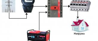
One striking example is switching an object to a backup source. Suppose you are tired of constant power outages in your country house and have acquired a gas generator. The electricians turned off the power, you switched to the generator. Turned it on - you are powering your house again from the standard network. Everything is simple in words, but how to do it practically? This is where a changeover switch will help you out. Take a look at the diagram below: In one switch position the house is connected to the mains, in the other it is connected to the generator. Moreover, even if there is voltage in both the network and the generator, switching does not threaten anything - it is impossible to connect the network to the generator. Unfortunately, although this scheme is simple, it is not entirely correct. Let's look at the actions you must take when connecting the generator:
- Disconnect the house from the standard electrical network.
- Start the generator and bring it into operating mode.
- Connect the house to the generator.
You don’t need to be a rocket scientist to understand that it is impossible to perform such a sequence of operations with a conventional changeover device. You will either have to start the generator first and then switch, or switch sources and then start the generator.
If the first option is still suitable, then the second is absolutely unacceptable for most household appliances. How will a refrigerator feel, for example, if during the startup of a gas generator the supply voltage begins to rise from 0 to 220 V, and the frequency from 0 to 50 Hz? If you don't know, it will burn.
Other switches.
Because In my switchboards I mainly use modules from ABB, but I don’t have many photos of Schneider Electric, Legrand, Hager switches.
I’ll say right away that these manufacturers do not have similar DIN-rail switches like ABB OT63, except perhaps Hager, who have a HAB switch for 20-63A in their product line.
Hager also has modular switches 1-4pole SBN series from 16 to 125A.
In one of the panels I used SBN 2P switches for 63A, which are quite nice, like the entire Hager module.
Schneider Electric also has modular circuit breakers 1P-4P of the iSW series for 20-125A.
I have not yet used Legrand modular switches. I managed either with automatic machines or in 3-phase switchboards with OT63 switches from ABB.
Thank you for your attention.
Distribution board diagram with a “network-generator” switch
Details Published: 04 June 2015
In dacha areas, garden plots, the private sector and similar places, frequent power outages are common. Here they can turn off the lights for an hour, for the whole day or for a longer time. This creates quite a few problems, since people can no longer imagine life without electricity. He has things working at home: a refrigerator, a TV, room lighting, a pump for watering the garden, and the like.
Gasoline power plants are very popular in such places. Turn off the lights, start the gas generator and continue to enjoy life. The power plant must be connected to the distribution board through a special outlet. Below I look at the diagram of a distribution board with a “mains-generator” switch, which allows you to switch to power supply from a gas generator when the external network is lost and back.
Here I am considering manual switching, which is carried out using a reversing switch. All diagrams show an ABB OT40F3C switch. This is a high-quality and reliable reversible switch. It has three positions:
- the handle is turned to the left - the contacts on its left side are closed, and on the right side they are open;
- the handle is in a vertical position - all contacts are open (both right and left);
- the handle is turned to the right - the contacts on its right side are closed, and on the left side they are open.
If what is written is not entirely clear, then look at the latest diagram and you will immediately understand how it works.
It is worth noting that if you take such a reversing switch for a higher current, then the switch handle is not included in the kit. It must be purchased separately.
Below is a simple single-phase switchboard diagram with a mains-generator switch. This is plenty for a small dacha or garden house. If you have a large house, then you need to revise the ratings of the input machine and increase the number of group lines. Everything is individual here.
It is very convenient to use a network indicator in such panels. For example, the signal lamp LS-47. Why is she needed here? Let's say the lights are turned off and you start the power plant. Everything is working.
Next, how to determine whether there is voltage in the network or not? You won’t run to the switchboard every half hour and use an indicator to check whether the light is on or not. This is not convenient and is forgotten over time. So you can miss this moment and “sit” on the gas generator until the evening. And gasoline is expensive these days.
In such a situation, the mains voltage indicator will immediately show you when the light comes on
It will just light up and you will immediately notice it. It is clearly visible from afar even through the transparent cover of the shield
As soon as the warning light came on, they immediately turned off the power plant and switched the switch to mains mode.
Below is the same diagram of the distribution board, but with an LS-47 signal lamp.
If you want to protect yourself and your dacha from current leaks, then you need to install an RCD. Below is a diagram with one common protective device. If you want more, then go ahead and fight. Here you can fantasize endlessly.
For a better understanding of the operation of such a circuit, I schematically showed the state of the contacts of the reversing switch with red lines and the direction of the current with red arrows.
Below is the work from an external network.
And here the work from a gas generator is already presented.
And these are already two diagrams of the operation of this switchboard in one. It looks like a cartoon. Like?
At the request of site visitors, I am posting below a 3-phase electrical panel diagram with a “network-generator” switch
Also don't forget to smile:
A drunk man goes home and hits his head on every lamppost. Then an acquaintance meets him and asks: “Why are you hitting the pillars like that, why are they bothering you?” Can't get around? “That’s not the point at all, it’s just how I determine the way home.” - Didn't understand. - What’s incomprehensible here? Here are 3 more pillars along this street, then 7 more along another - and I’m home.
Single-phase generator for three-phase network.
Consult specialists. There is a three-phase network in a country house, but sometimes there are outages for 5-8 hours. There is a task to provide power to several consumers - three refrigerators, a pump, a septic tank, a water heater (storage), light. The trouble is that these consumers are scattered into different phases, and there is no point in buying a three-phase generator, because firstly, there is not a single three-phase consumer, and secondly, it is expensive. I would like to use one lever to switch to the gene during a power outage, so that all phases can be closed to one. The generator will have a manual start, if anything... but the main thing is that when the network is turned on, the housewife herself unmistakably turns it on properly. Tell me how to implement this more safely.
MIB wrote: There is a task to provide power to several consumers - three refrigerators, a pump, a septic tank, a water heater (storage), light.
We are silent about the other.
MIB wrote: The trouble is that these consumers are scattered into different phases
it's not a problem it's so nada
MIB wrote: there is no point in buying a three-phase generator, because firstly there is not a single three-phase consumer, and secondly it is expensive.
but much more powerful than single-phase, you will decide what you need more - electricity or chug-puff. In principle, it is possible to short-circuit the phases, but what is the total power consumption?
MIB wrote: because firstly there is not a single three-phase consumer
Then, indeed, you can get by with single-phase. With power, yes, you need to decide. You can switch it with a changeover switch, preferably 4 poles, if you can find one. Like these » >
I solved the same problem in the workshop at work - three-phase input, frequent shutdowns for “prevention”, from 10 to 18 hours. If there are no three-phase consumers (motors, transformers, which is of course rare in a private home, stabilizers!), then you can use a reversing switch from ABB » > or » > depending on the allocated power. Connect a three-phase input to one group, combine the second group of contacts and connect to the generator. When using these switches, the possibility of the generator operating on the network or in conjunction with the network is completely excluded.
3KW, maximum 3.5KW, so I don’t see the point in a three-phase generator, after all, emergency power supply for the most necessary things. Moreover, you can sacrifice a water heater .. and generally get by with 2.5 kW (with a margin).
2Merlin666 I'm trying to find a diagram of how the reversing switch works - does it simply cut the network and close all the phases together?
no, it has two three-phase inputs and one three-phase output. The switch has three handle positions - in the first position the first group of phases is connected to the output, the second position is zero (the output is not connected anywhere), the third position is the second group of phases is connected to the output. To work, connect the wires that you now have as input to the output, connect the input that you had to the first group of contacts on the switch, in the second group of contacts, connect all the contacts to each other, and connect one of the generator outputs to these contacts , which will now be a phase. Connect the second terminal of the generator to the neutral bus.
By the way, be sure to look in the instructions to see if you have an inverter generator; if it’s just synchronous or asynchronous, then that’s it - I’m just not sure whether the inverter generator will work normally with a solidly grounded neutral.
In normal mode - the switch is in position 1 - all consumers work from the network; when you turn off the power, you start the generator, warm it up, and use the switch to switch the input to it. Alright, turn off the generator and switch the input back to the network. The most important thing here is protection from the “fool”; even if you switch the switch while the generator is running or there is electricity in the network, there will be no consequences. The same problem can be solved using load switches, in principle, it will be 10 times cheaper, but the circuit will not be foolproof at all.
Connection features
The choice of connection diagram for a changeover switch is influenced by the type of electrical network.
Single-phase network
You can connect such a device to this network only if it has two poles. In addition, you need to take into account that the operation of the switch is only possible if there is a power supply with suitable technical characteristics. As for jumpers that provide contact between two-pole devices, it is advisable to give preference to copper ones.
Two-phase network
How to connect a switch with your own hands if the network is two-phase? The circuit involves the use of a 200V power supply. Also, for these devices you need to use only expansion switches. Only then can the devices be used in a three-phase power supply network, regardless of the number of modules used.
The maximum voltage for such devices will be 300V, and the maximum negative resistance will be 40 Ohms. The contacts in such devices are applicable exclusively to closed models, and fluctuations in electrical energy are controlled using pass-type capacitors.
Three-phase network
For this type of electrical network, reversible switches are used. They provide a complete uninterrupted supply of electric current, distributing the load over several lines and completely preserving the power supply. Here you need to use 400 V power supplies. It would also be appropriate to use pulse transformers.
Double pole switches
It is the two-way changeover switch that is installed in multi-storey buildings. It can be used to service units connected to both single-phase and two-phase systems. Average negative resistance values are at 60 ohms.
The output voltage may not be the same, depending on the modification of the device. Devices from the PP20 series with open capacitors are often used. When connecting them, you cannot do without power supplies with an operating voltage of 300 V.
How to connect a generator
I didn’t want to connect the generator through the ATS circuit, because I don’t have the knowledge or funds for this, but I decided to do everything myself and connect it without automation.
The store advised me to connect the generator directly through the outlet, but I did not do so for safety reasons. And they offered and sold me this adapter:
Cable with plugs for connecting the generator to an outlet
To make using the generator safer, I made the following socket for it on the wall of the summer kitchen:
Generator socket
The SSI-114 type socket has a cover that protects live parts. But there will always be voltage on it - both when the generator is running and from the street! I secured it higher so that the children couldn’t reach it.
I made another adapter for connection so as not to confuse it with anything else, and signed the danger warnings.
Connection cable
The fork looks like this:
Generator output plug
This is the most dangerous place in the structure. But how to avoid trouble is the secret in the connection sequence, more on that later.
Rocker switches
These devices have all the properties of changeover switches, but do not have the disadvantages of the latter. Thanks to the special design of the switches, the energy of the operator's hand is not directly used to move the knives, but is accumulated to a certain value, and then makes a quick switching "click". This significantly reduces switching times, reduces the possibility of arcing and allows switching under load. In addition, working with switches is safer, since the devices almost always have a closed design, which means that even an untrained person with zero knowledge of electrical engineering can make switches.
There is an opinion that switches are inferior to switches in power, but this is not entirely true. There are devices capable of switching the same hundreds of amperes, even under load. They are simply quite cumbersome in design and much more complex than conventional switches. Like switches, switches can be three-position and multi-sectional.
Connection diagrams
Please note that the procedure for connecting the device may differ depending on the type of electrical network.
Connecting devices to a single-phase network
Connecting such a switch to a single-phase circuit is possible only if the selected device is made in a two-pole version. It is also necessary to keep in mind that this device can only function with a power supply whose operating voltage is 300 V.
- For such a modification, the negative resistance indicator will reach 50 Ohms. An important point is that sometimes these switches are supplemented with counters. But such a device as switches can rarely be found when using changeover switches.
- When choosing jumpers to ensure contact between two-pole modifications, only those made of copper should be used.
- To install such devices in residential buildings, you should make sure that there are electrical panels of the KK202 series and other modifications. Due to the discrepancy in performance characteristics, reversing units are not recommended for single-phase circuits.
Connecting the device to a two-phase network
If we talk about the voltage limit with which they are able to cope, then this is the level of 300 V. In such a combination, these switches will be subject to a load that will be about 20 A. Most often, the choice is made on such models of switches, which represent the PP30 series.
According to their design, they are equipped with only two modules. With this design, they will be able to provide an output voltage corresponding to a value of 350 V. The blockers used in them can have different designs
For servicing residential buildings, it is important to ensure that there is an electrical panel. This is a requirement
But the design of control units usually contains thyristors. For the network, the limit of negative resistance is 40 ohms. The contact systems that are implemented in such switches are applicable only to closed-type models. In this case, control of electricity fluctuations is ensured by feed-through capacitors. A device such as a reversing unit performs the task of maintaining the required current frequency. If the choice was made on two different models, then they must be used in combination with the controller. This, in turn, makes it possible to minimize the negative effect of nonlinear distortions that appear in the circuit.
Connection diagram to a three-phase network
In the case of installing a switch in a three-phase circuit, it is necessary to use power supplies with an operating voltage of 400 V. It is worth noting that for such purposes it is allowed to use transformers made exclusively in the pulse version.
- The procedure for connecting the device itself is performed using an inverting input. The output current is supplied through a special device, the role of which is performed by pass-through capacitors. For such cases, it is advisable to use switches of a two-module design.
- At the same time, single-module modifications can also be found on sale. Their feature is the minimum threshold voltage limit, corresponding to a level of 350 V. As for the negative resistance indicator, its value in the circuit can correspond to a value of 55 Ohms. To solve this problem, care should be taken to ensure that the design of the switch contains a device such as a blocker.
- Residential buildings must be equipped with special electrical panels, representing the KK22 series. Control units used for such situations can include in their design not only thyristors, but also dinistors.
Single pole switches
In many cases, devices with only one module are used . In such modifications, copper conductors. It is important to know that they should be used to service generators whose operating frequency range is not higher than 20 Hz. There are also certain disadvantages that are taken into account when choosing.
An important nuance: the maximum load during use should not exceed 200 A. Therefore, they are not installed in residential buildings where there is significant electricity consumption. Another feature: low output voltage, mostly 200 V.
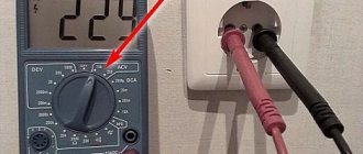
How to connect a generator to the network at home: diagram
The circuit is made for an electrical network and a generator. Switching can occur in manual or automatic mode
It is especially important where the insertion point of the switch is located. It must be located after the electric meter, but before the protective device
Let's first study the manual switching circuit. If the voltage disappears, use a switch or circuit breaker to break the connection to the central network and activate the generator. The switch must not implement these two actions at the same time. Be sure to provide a neutral position in the installation for subsequent connection.
It turns out that changeover or reversing switches can serve as a manual switch. When making a choice, you need to take into account the rated currents so that they are not lower than what is consumed. The process of how to connect a generator to the network at home varies. The layout and even the design of the devices may also differ. Look at the image below. It shows the connection of a three-phase generator.
In addition to the manual method, sometimes an indicator is installed that determines the presence or absence of voltage in the centralized network. An example of devices would be 220 V modular indicators or 220 V light indicators (twenty times cheaper), which have a closed housing and ready-made wiring. Their disadvantage is that they are connected to the fuse.
When automatically switching an electric generator, as the name implies, the process occurs without human intervention, automatically. The function falls on the ABP block. It consists of various devices: switches, indication parts, voltage control relays, contactors.
Such a generator must be equipped with an electric starter. To enable the reserve, the centralized network is turned off, the generator starts, warms up, and the wiring is connected to the consumer network. If voltage is supplied to the network again, the process is turned off in the reverse order.
Backup automatic entry can be carried out by different systems. You can look at the process by taking the GG700E gasoline generator model as an example. The connection starts after the voltage from the centralized network disappears. In just twelve seconds, all consumers at home will be provided with electrical energy.
The system is also capable of monitoring the stability of the energy supply. If operation occurs smoothly and continuously for more than ten seconds, then power begins to be supplied again through the common network. The device continues to operate for a few more seconds to check, and then turns off.
Automatic generator start via AVR unit
The purpose of such devices is to partially or completely eliminate human participation in the operation of the generator. There are two main types of such devices. The first completely copies the auto-switching system, which operates on two starters, but with the addition of an electronic unit for starting and stopping the generator. A low-current cable is connected to it from the main power supply line, through which the unit receives information about the presence or absence of voltage in the network. Depending on this, it sends a command to the engine to start or stop, and switching between input from the main line or from the generator is performed by the starters themselves. In general, this is the same system as the proposed scheme for self-assembly, but here you don’t have to invent anything - just install a ready-made unit.
The disadvantage of such a block is the same - its purpose is only to start and stop the engine without additional protection.
The diagram itself looks like this:
1. Introductory machine. 2. Electricity meter. 3. Automatic generator start block. 4. Generator. 5. Time relay. 6. RCD. 7. Main input contactor. 8. Backup input contactor.
A more advanced option is a complex system controlled by microprocessor electronics. In general, it works in the same way as a homemade autostart system, but its main advantage is the presence of numerous sensors that monitor all aspects of the generator's operation. If any equipment malfunction occurs, the ATS unit will be able to react adequately - not torment the generator with autostart attempts, but if there is a GSM module, send a message to the owner about the malfunction.
The ATS unit itself is mounted instead of a distribution panel - this does not require much knowledge - you just need to connect wires from the main line, power and control cables from the generator and output to the house to it.
1. Introductory machine. 2. Electricity meter. 3. AVR. 4.Generator. 5. Control cable. 6. Consumer machines. 7. Zero bus. 8. Grounding bus.
Such a unit is a complex set of equipment and its cost in some cases can be equal to the price of a generator. Therefore, its purchase is justified only in case of frequent power outages and for sufficiently powerful generators.
Advantages and disadvantages of switches
It remains to consider the advantages and disadvantages of these devices. The advantages include:
- Visibility. The device usually has an open or semi-closed design, which means that its serviceability can be verified visually. Well, since you can clearly see the conductive knives and tires, it will not be difficult to determine in what position the breaker is located.
- Simple design. Almost all such switches, including changeover switches, have an extremely simple design. They are very durable, easy to maintain, and their repair usually does not require high qualifications and is inexpensive.
- High switching power/cost ratio. This is perhaps one of the main advantages of the devices. Some of these devices can switch currents of hundreds of amperes, and are relatively inexpensive.
But switch-type switches also have disadvantages. Here they are:
- Increased danger for the operator. Since most devices have an open design, it is very easy to get energized if handled carelessly. Therefore, only qualified personnel are usually allowed to work with such switches, and the switch itself is often placed in a closed cabinet or housing.
- Irregular switching time. The switching speed of almost any switch depends only on the operator’s reaction. When the knives are slowly moved under load, a high-temperature arc can “stretch” between the opening contacts, which is equally dangerous for both the equipment and the operator himself*.
Arc suppression inserts, which are equipped with some types of switches, help fight the arc only partially. That is why the vast majority of electrical equipment manufacturers recommend switching using switch devices only after removing the load using intermediate circuit breakers.
What is a changeover switch
What an ordinary switch is, perhaps everyone who is more or less familiar with electricity . In essence, this is an ordinary switch, only large and powerful. The handle is in one position - the circuit is closed. In the other it is open. If the switch switches one line, then the device is single-pole, and when you can switch several circuits at once with one handle, then it is multi-pole.
Unlike a conventional switch, a changeover switch has additional contacts, thanks to which the device can not only turn on or off electrical equipment, but also switch. In one position of the handle, the middle bus of the switch is connected to the upper contacts, in the other - to the lower ones.
The most important thing about this design is that the upper and lower busbars cannot be connected under any circumstances. This is what makes the device indispensable when switching equipment that does not allow connections between each other during the switching process. Take a look at the diagram below:
In one position, the lamp is powered by the upper battery according to the circuit, in the other – by the lower one. No matter how hard you try, you will not be able to connect the batteries together. What does this give? Suppose the polarity of the batteries is reversed, and instead of a light bulb you used an electric motor.
In one position of the switch the motor rotates in one direction, in the other - in the opposite direction. But if you accidentally connect the batteries together, then serious problems will begin - a short circuit. In the above example, you only risk draining the batteries, but if you switch more serious circuits - for example, voltages from various power lines - then the slightest mistake by an operator operating conventional switches can lead to a serious accident. A changeover switch, due to its design, will not allow such disgrace, since you simply will not have erroneous options - “either-or”.
The advantages of a changeover switch over a pair of conventional switches are obvious. But what to do if the light bulb in the diagram above just needs to be turned off? Install an additional switch? Not at all necessary, since there are three-position changeover switches. Unlike their two-position counterparts, they have one more position, the so-called intermediate, in which one source from the load is already disconnected, but the second is not yet connected.
Thus, using a three-position switch , you can not only make a switch with one movement of your hand, but also disconnect the load from the source:
How to connect a power plant to a house via a changeover switch
Remember that the generator must be completely disconnected from the existing electrical network, i.e. It is necessary to disconnect not only the phase, but also the zero.
The simplest and most inexpensive ways to connect a generator to your home with your own hands:
- Through a changeover switch (in the picture on the left).
- Through a three-way reversing switch or three-position switch (in the figure on the right).
If the changeover switch is installed separately, then the three-way changeover switch is provided for mounting under a standard DIN rail in the electrical panel. For a single-phase network, two poles are sufficient (for a phase + zero break), and for a three-phase network, a four-pole one is required (for a three-phase ABC and zero break).
Three lines are connected to a three-way switch or changeover switch: one from a stationary power supply network, the second from a generator, and the third to electrical consumers. They have three switching positions:
- Mains power is on.
- Generator power is on.
- Everything is disabled.
The design of a changeover switch or three-way switch eliminates the possibility of simultaneously turning on a stationary power supply and a generator. That is, either the power plant is turned on, or power from a stationary electrical network is turned on, or everything is turned off.
Let's look at the do-it-yourself connection diagram for a changeover switch. The three-way switch will be connected in the same way according to the diagram printed on it or from the instructions.
All work must be carried out only after removing the voltage, checking its absence and taking measures to prevent its accidental activation.
An external power supply is connected to the upper jaws or contacts, a power station to the lower ones, and home electrical consumers to the middle ones.
In the event of a power outage, you must:
- Start the electric generator manually and give the gasoline generator a few seconds to warm up.
- Switch the changeover switch to the lower position as shown in the diagram.
When voltage appears in the external power supply, switch the switch to the previous position and then turn off the generator.
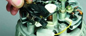
Photos of an ABB reversing switch, photos of a changeover, modular switch.
Due to possible discrepancies in performance characteristics, reversing units are not used for single-phase circuits. Video Modern electrical circuits are switched by various devices produced in a wide range.
First of all, it is installed in residential buildings. Such devices are called two-position devices. By means of reversible blocks, the required current frequency is supported.
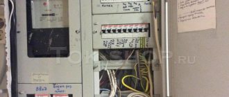
And this is how distribution boards are mainly installed - they have a circuit breaker installed at each input.
A DIN rail can also be used here to accommodate modular protective equipment.
It is also important to remember that for this device it is necessary to use only expansion type switches. The dimensions of the shield are selected according to the number of installed modules. Circuit breakers - polarity and connection diagrams
More on the topic: Measuring loop resistance phase zero
Installation and connection rules
Changeover switches are installed inside distribution boards - ASU. For modular devices, standard DIN rails are provided. The dimensions of the shield are selected according to the number of installed modules. Switches in the usual design are mounted on specially designated mounting panels. A DIN rail can also be used here to accommodate modular protective equipment.
Shields made of plastic or metal are used indoors, and only metal products with the required degree of protection are installed outside.
The main cable supplied from the metering board is connected to one of the inputs of the switching device. The other input is for the backup cable connected to the generator. If the switch has only one output, a cable coming from the distribution panel is connected to it. Modular devices usually have 2 inputs and 2 outputs. The outputs are connected in parallel using jumpers, after which they are connected together to the distribution board.
Such a connection is clearly visible in the example of a single-phase network, to which a three-pole changeover switch is connected, connecting the generator to the electrical network. The main requirement for carrying out such a procedure is to maintain polarity. Correct connection will allow you to avoid changing the positions of phase and zero when making switchings. At the network input, protection is installed in the form of a circuit breaker located in the metering panel. The input coming from the generator is also protected by a machine installed in the panel along with the switch.
Connecting the device can additionally use automatic transfer of a reserve - ATS, or the reserve is switched on manually using an automatic machine. In the case of using changeover switches, such switching is performed without load. First, the load is switched off automatically, and only then all the necessary manipulations with the switch are carried out.
If the design of the switch includes an arc extinguishing device, then switching can be done directly, without first turning off the machine. However, the circuit on all lines must necessarily include fuses or circuit breakers, since the switch itself will not be able to protect the network in an emergency.
Operation of the changeover switch will be safe if you follow the installation rules and recommendations of specialists:
- For installation and further work it is better to use a closed room.
- Switching equipment is reliably protected from moisture and negative external environmental influences.
- The temperature limit at which normal operation is possible is from minus 40 to plus 55 degrees.
- Installation of the changeover switch and its fastening must be strong and reliable.
When installing the device outdoors, you should first ensure protection from external influences. At possible low temperatures beyond the permissible limits, a heating system for the cabinet should be provided in advance. All work on installation, maintenance and repair of switching equipment must be carried out by qualified specialists, with the network completely disconnected.
Features of using a three-position switch
Three-Position Change-Over Switch
A three-pole changeover switch is suitable for connecting backup power to a home line. It is used only after the load has been disconnected. The generator will need to be activated and set to working position. Then you need to connect your home network to it. When carrying out repair work, the switch will be used as a disconnector.
Device installation
Changeover electrical equipment is installed in the switchboard. Models with a plastic case are suitable for indoor installation, and metal ones for external installation. Inside the boxes there is a special DIN rail for switches. Installation of devices is carried out as follows:
- Models that switch off under load are installed vertically.
- The type of tires and wires is selected. Their cross section must correspond to the current rating of the switches.
- Buses and wires are connected to fixed contacts.
- The elements are tightly clamped with terminals to ensure reliable contacts and eliminate the possibility of overheating.
- The threads of the nuts are coated with Vaseline.
- Contact nuts tighten smoothly. After the first turn of the wrench, the nut is loosened and then carefully tightened.
- Castor oil is applied to the surface of the contact knives, which will prevent them from jamming in the racks.
- Metal non-current-carrying elements are grounded on the outer part of the box.
Switching order
Before connecting, you must stop the input machine
Three-position or package devices are produced without a disconnector. They connect like this:
- Stopping the introductory machine.
- Installing the device handle on the generator line.
- Switching off the load breaker.
- Connecting the switch cable to the generator socket.
- Start the generator, wait for warm-up (2 minutes).
- Supplying power to the switch.
- Turning on the load breakers.
Machines are installed on each of the inputs.
Types of switches for generators
When choosing products for generators, it is best to give preference to single-module switches. If we are talking about a blocker, then it must be equipped with a classic contact system. The design of reversible blocks often contains a controller. That is why you should not opt for systems with a resonator.
In such situations, the threshold frequency will be high. Products used for generators may vary in size
It is important to pay special attention to the number of capacitors
Before installing generator products, it is necessary to carefully study the grounding system. Full operation of the device is possible in the presence of a grounding electrode. The labeling of the latter must necessarily contain information about the protection system, in most cases this is IP30. Based on this information, you can safely judge the reliable insulation of the device. Such a system will function over many cycles.
Two-way systems
When purchasing changeover switches, it is important to take into account the fact that they can only be used in single-phase circuits. The design must contain two pass capacitors
Manufacturers produce not only two-, but also three-module systems. They can operate with a power supply having a voltage of 300 V. The connection diagram for such a device often involves the use of a meter. Installation is carried out using copper jumpers. Operation of the units is possible in conjunction with expansion switches.
Changeover switches are designed for a voltage of 350 V, the load may vary. The determining factor is the manufacturer. The average load is 30 A.
Three-way modifications
If we look at these changeover switches in detail, it is important to note that they are equipped only with expansion switches. This is the most suitable option for use in two-phase circuits
Products are in wide demand on an industrial scale. Their operation in an enterprise is possible if connected to an electrical panel of the KK202 series.
Often, jumpers are made of copper; blockers may differ in design. A feature of the products is a high sensitivity limit. In addition, they are equipped with a reliable protection system. Insulation comes in different classes. The determining factor when choosing is the manufacturer.
Thus, products of the SFT 250A series are installed exclusively in conjunction with power supplies with voltages of 200 and 300 V. The connection diagram for such devices provides for the use of pass-through capacitors. This is necessary so that the load is no more than 3 Amps. Often systems operate with analog switches. In addition, units manufactured in an expansion version are common.
. When connecting meters, they need to be allocated a special place behind the contact system. Reversing units must be equipped with a resonator and a controller. The choice must be made taking into account the peak frequency of the product.
Generator switches are an effective solution and provide many benefits. In addition to convenient maintenance, it is possible to monitor network characteristics. This minimizes the risk of dangerous situations affecting the functioning of devices connected to the network
When choosing devices, you need to pay special attention to the parameters of the included elements, as well as the room where installation is planned
Generator switches
Changeover switches for generators are single-module. The interlock block contains a classic version of the contact group. Reversing blocks are produced together with the controller.
Before installation, it is necessary to evaluate the quality of the grounding circuit. For effective operation, the presence of a grounding electrode is necessary. Examine the marking, which usually looks like IP30, which indicates the presence of high-quality insulation of the material. This will guarantee a large resource.
ABB changeover switches are special load switches that ensure uninterrupted power supply. There are many types of devices that can be used for different types of networks
When purchasing, you should pay attention to the labeling and compliance with safety standards.
Application of ABP
The autostart system is more expensive than the manual one, but it constantly monitors the network voltage. When the voltage disappears, the contactor interrupts the connection between the ATS and the central power grid. The starter turns on and the generator starts working. Most generator owners prefer using cheaper partial automation, which works as follows:
- The main power supply is connected through a contactor that opens when the input is disconnected.
- The gas generator is started manually. A time relay is installed in it to warm up the engine and automatically switch to connecting the reserve to the home network.
- When the power supply is restored, the contactor is switched off and the load is supplied again from the public network.
A fully automated power supply system regulates the operation of the gas generator using microprocessors. Video on this topic
Connection diagram for a backup generator to a three-phase network. Connecting a generator and a 3-phase network
Let's consider the key points of connecting a single-phase generator to a three-phase network. Recently, this topic was created on the forum, and I decided to give a more detailed answer, as well as discuss this issue on the blog, since many readers do not visit the forum.
Connecting a single-phase generator is relevant for private houses and cottages that want to have an independent power source.
Many luxury houses (cottages) have three-phase input due to high power consumption. Here the question may arise: what kind of generator is needed? A three-phase generator of the required power suggests itself.
Generator for a private home
Is a three-phase generator really necessary?
I will not give a definitive answer to this answer, however, I assume that a single-phase generator will be cheaper than a three-phase one.
I have already told you why three-phase input is bad. The main problem is that it is very difficult to achieve uniform phase distribution. Perhaps the generator does not tolerate operating modes very well when there is constant phase imbalance.
But how can we convert our three-phase shield into a single-phase one?
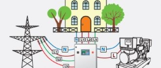
Everything is very simple. Scheme for automatically connecting a single-phase generator to a three-phase network:
Connection diagram of a single-phase DG to a three-phase network
For this we need only 2 contactors, not counting the auxiliary elements.
In normal mode, consumers are connected to a three-phase network through the KM1 contactor. If the main power is turned off, the generator starts. Starting can be done using the additional contact of the KM1 contactor. Contactor KM1 is turned off, and contactor KM2 is turned on and combines phase 3 into one.
If you do not need automatic starting of the generator, then instead of this ATS you can use, for example, a cam switch for the appropriate power. The connection diagram is similar to KM2. Here we must use either two manual switches or 1 switch, and turn off the supply network with an input circuit breaker.
Which solution is preferable? The choice is yours.
I also advise you to review my old articles:
Standard start-up of the generator
Fig. No. 1. Three-phase circuit for automatic restoration of working power supply from a household generator.
To start the generator, a push-button station with “start” (KB) and “stop” (KO) buttons is provided. The RKN relay performs the function of a blocking element of the circuit.
If the main power goes out, some DIY steps are required to start the generator. Approaching the generator, we check the presence of fuel in the tank, the condition of the oil system, and spark plugs. We turn on the ignition key, open the fuel and choke, and start starting. After starting, turn on the introductory machine and the “start” button. Automatic activation is very conditional.
After the main power is supplied, the voltage control relay is turned on, the PM2 coil breaks the circuit, the command to turn off the PM makes it possible to start the starter on the main input of PM1. After this, we stop the generator engine. This is the so-called simplified scheme for starting a backup generator.
Changeover switch principle of operation
An electrical type device that serves to disconnect an electrical load from one energy source and connect it to another source is called a changeover switch, or a changeover type switch (switch with a midpoint). The devices are available with or without arc arresters. In the first case, network switching can occur with a fully connected load. In the second - only when it is turned off.
The switch is operated manually, that is, if it is necessary to switch power sources, the operator acts on the isolated control lever of the switch. There are also automatic switching systems.
Features of the device
Switches are manufactured according to different technical characteristics and parameters. There are many types and models that are commonly installed in residential areas. The main feature is that switching between networks occurs with an open circuit, and there are three positions:
- I City (home line).
- 0 Off.
- II Power supply from generator.
With the help of such devices, manual switching occurs between the main network and backup power. After turning off the power to the main network, you can start the generator and move the switch knob to the desired position.
CONNECTING A GENERATOR TO A PRIVATE HOUSE - VIDEO
This type of connection is strongly recommended by experts, since it is not only very reliable, but also provides the necessary comfort.
For those who know electrical engineering at a professional level, this method is better than all others. It involves the installation and use of an automatic transfer switchboard (ATS). As soon as the centralized power supply is turned off, the controller or relay of the ATS unit will start an autonomous source without human intervention and after some time transfer the load to it (Fig. 2).
If you understand that your qualifications are not high enough, then you should limit yourself to the stage of connecting the ATS unit, and involve a specialized organization in the assembly of this shield. This will protect the house from incorrect circuit solutions. For example, the absence of a mechanical interlock for the simultaneous activation of a pair of contactors can lead to parallel operation of the generator and the network, the consequences of which will be disastrous for both the equipment and the building.
Mini-power plants equipped with an electric starter, which, upon receiving a signal from the ATS, will start the generator, have the ability to connect via an automatic transfer switch. If the purchased model of an autonomous source is designed only for manual start-up mode, then the AVR. of course, will switch the consumer circuit to an autonomous source and back when the centralized power supply is restored. But you will have to turn the generator on and off manually. In this situation, it is more advisable to limit yourself to connecting the generator through a three-position switch-disconnector.
When contacting third-party contractors or making your own connection, you must strictly follow the manufacturer’s recommendations for installing and operating the generator, including the requirements for the presence of protective grounding. Only technically correct connection using reliable switching and protective devices guarantees long-term and trouble-free service of the entire in-house electrical network.