Considering that power supply is traditionally carried out by delivering alternating current to consumers, the desire to create electric machines that operate on supplied electricity is understandable. In particular, alternating current is actively used in asynchronous electric motors, which are widely used in many areas of human activity. The induction motor with a squirrel-cage rotor deserves special attention, which, for a number of reasons, has taken a strong position in application.
The secret of such popularity lies, first of all, in the simplicity of the design and the low cost of its manufacture. Electric motors with squirrel-cage rotors have other advantages, which you will learn about in this article. First, let's look at the design features of this type of electric motor.
Design options
Special version
C – asynchronous electric motor with increased slip level. It takes a long time for the rotor to stop completely
P – with increased starting torque. For systems requiring high power at startup
K – with wound rotor
Read also: Natural logarithm and its properties
E – with a built-in electromagnetic braking mechanism to ensure quick stop of the motor rotor
Asynchronous three-phase electric motors AIR
Among the variety of domestic and imported engines, it is worth noting the popular AIR brand. There are more than 300 models on sale with various designs. They have gained enormous popularity due to their high reliability, maintainability and low cost.
Where are electric motors used:
- – for ventilation systems
- – for printing machines
- – for grinders and machines
- – for driving air compressors
In these areas, it is possible to use both high-speed and low-speed models (with a rotation speed of less than 1000). Imported products are marked rpm.
Asynchronous electric motor
The English-language reference book calls an asynchronous electric motor an induction motor. Immediately the i's are dotted. The Internet is full of questions about the differences between this type of machine, the nuances of commutator and synchronous engines, but in reality it turns out to be simple. The only type of motor that creates poles by the phenomenon of induction. Other designs use permanent magnets, coils powered by current... Only induction (asynchronous) motors use interference that creates a driving force. The factor determines the feature - the difference between the shaft rotation speed and the field frequency.
Motor mode
If the rotor is stationary or its rotation frequency is less than synchronous, then the rotating magnetic field crosses the conductors of the rotor winding and induces an emf in them, under the influence of which current begins to flow through the rotor winding. The current-carrying conductors of this winding, located in the magnetic field of the excitation winding, are subject to electromagnetic forces; their total force forms an electromagnetic torque that drags the rotor behind the magnetic field. If this moment is large enough, then the rotor begins to rotate, and its steady rotation speed
[rpm] corresponds to the equality of the electromagnetic braking torque created by the load on the shaft, the friction forces in the bearings and the inertia of the rotor. The rotation frequency of the rotor cannot reach the rotation frequency of the magnetic field, since in this case the angular speed of rotation of the magnetic field relative to the rotor winding will become equal to zero, the magnetic field will cease to induce EMF in the rotor winding and, in turn, create torque; Thus, for the motor mode of operation of an asynchronous machine, the following inequality is true:
The relative difference in the rotation frequencies of the magnetic field and the rotor is called slip
:
.
It is obvious that in the motor mode
.
Principle of operation
The operation of an asynchronous motor is based on the property of a three-phase current, capable of creating a rotating magnetic field in the stator windings. In the electric motors under consideration, the synchronous rotation frequency of the electromagnetic field is directly proportional to the natural frequency of the alternating current.
There is an inversely proportional dependence of the rotation speed on the number of pole pairs in the stator windings. Considering that the phase shift is 60º, the dependence of the rotor speed (in rpm) can be expressed by the formula:
n1 = (f1*60) / p, where n1 is the synchronous frequency, f1 is the AC frequency, and p is the number of pole pairs.
As a result of the action of magnetic induction on the rotor core, an emf will arise in it, which, in turn, causes the appearance of an electric current in a closed conductor. An Ampere force will arise, under the influence of which the closed loop will begin to rotate in pursuit of the magnetic field. In the nominal operating mode, the rotor rotation speed is slightly behind the rotation speed of the magnetic field created in the stator. When the frequencies coincide, the magnetic flux stops, the current disappears in the rotor windings, as a result of which the force ceases. As soon as the shaft rotation speed lags behind, the action of the ampere force is resumed by alternating currents of magnetic fields.
The difference in the rotation frequencies of the magnetic fields is called the slip frequency: ns=n1–n2, and the relative value s, which characterizes the lag, is called slip.
s = 100% * (ns / n1) = 100% * (n1 - n2) / n1, where ns is the slip frequency; n1, n2 – rotation frequencies of stator and rotor magnetic fields, respectively.
In order to reduce the harmonics of the EMF and smooth out the pulsations of the moment of force, the rods of the short-circuited turns are slightly beveled. Take another look at Fig. 2 and pay attention to the location of the rods that act as rotor windings relative to the axis of rotation.
Slip depends on the mechanical load applied to the motor shaft. In asynchronous electric motors, the sliding parameters change in the range from 0 to 1. Moreover, in idle mode, the rotor that has gained speed experiences almost no active resistance. S approaches zero.
An increase in load contributes to an increase in slip, which can reach unity when the engine stops due to overload. This condition is equivalent to a short circuit and can damage the device.
The relative value of the lag corresponding to the rated load of the electrical machine is called the rated slip. For low-power electric motors and medium-power engines, this figure varies within small limits - from 8% to 2%. When the electric motor rotor is stationary, the slip tends to 0, and when idling it approaches 100%.
When starting an electric motor, its windings are under load, which leads to a sharp increase in starting currents. When the rated power is reached, electric motors with squirrel-cage turns independently restore the rated rotor frequency.
Pay attention to the sliding torque curve shown in Fig. 3.
Rice. 3. Sliding torque curve
As the torque increases, the coefficient s changes from 1 to 0 (see the segment “motor region”). The shaft rotation speed also increases. If the shaft rotation speed exceeds the rated frequency, the torque will become negative and the engine will go into generation mode (the “generating region” segment). In this mode, the rotor will experience magnetic resistance, which will lead to braking of the motor. The oscillatory process will be repeated until the torque stabilizes and the slip approaches the nominal value.
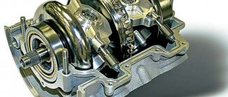
Squirrel cage rotor
Ideas about the phenomenon of electromagnetic induction will tell us what will happen to a closed coil of conductor placed in a rotating magnetic field, similar to the magnetic field of the stator of an asynchronous motor. If you place such a coil inside the stator, then when current is applied to the stator winding, an EMF will be induced in the coil, and a current will appear, that is, the picture will take the form: a coil with a current in a magnetic field. Then a pair of Ampere forces will act on such a coil (closed loop), and the coil will begin to rotate following the movement of the magnetic flux.
This is how an asynchronous motor with a squirrel-cage rotor works, only instead of a coil there are copper or aluminum rods on its rotor, short-circuited with each other by rings at the ends of the rotor core. A rotor with such squirrel-cage rods is called a squirrel-cage or “squirrel-cage” rotor because the rods located on the rotor resemble a squirrel wheel.
Squirrel-cage rotor and squirrel fiber
The alternating current passing through the stator windings, generating a rotating magnetic field, induces current in the closed circuits of the “squirrel cage”, and the entire rotor begins to rotate. Since at each moment of time different pairs of rotor rods will have different induced currents: some rods will have large currents, some will have smaller ones, depending on the position of certain rods relative to the field. And the moments will never balance the rotor, so it will rotate while alternating current flows through the stator windings.
Squirrel-cage rotor of an asynchronous electric motor
In addition, the squirrel cage rods are slightly inclined relative to the axis of rotation - they are not parallel to the shaft. The tilt is made so that the torque remains constant and does not pulsate; in addition, the tilt of the rods allows us to reduce the effect of higher harmonics induced in the EMF rods. If the rods were not tilted, the magnetic field in the rotor would pulsate.
Varieties of the simplest transformer engines
AC motors can be synchronous. The circuit turns out to be simpler, and the motor is cheaper. Although all induction motors contain a stator similar to a synchronous machine, the design of the rotor makes them significantly different. It does not need to be magnetized in one way or another, as is done in a synchronous engine. Despite the differences between the models of asynchronous machines, the design of their rotor is the equivalent of a short-circuited secondary winding.
The simplest option is a squirrel cage rotor. It can simply be cast from a ferromagnetic material and processed properly. Iron-based alloys conduct electrical current and interact with magnetic fields. The all-metal design has the following advantages:
- the easiest to manufacture and for this reason has the lowest cost;
- best withstands the forces generated during engine operation;
- accelerates well due to the effective interaction of magnetic fields.
All metal version
How to overcome the disadvantages of blanks
However, it is quite obvious that such a squirrel-cage rotor will not be the best conductor for currents induced by the stator. Iron alloys conduct electricity much worse than aluminum or copper. In addition, it is not without reason that the magnetic cores of transformers are made of steel plates, and not of cylindrical blanks. Eddy currents heat up the cast metal and reduce the overall efficiency of the electrical installation. Therefore, the disadvantages of the massiveness of the iron alloy structure are structurally taken into account by the most efficient engine with a squirrel-cage rotor.
This electric motor uses aluminum or copper parts. The functions in relation to the creation of a magnetic field and current conduction are structurally separated. To obtain an alternating magnetic field with low losses, by analogy with transformers, thin insulated plates are used. Each of them contains recesses and is equivalent in shape to the cross section of the rotor. Its material is transformer steel.
How to make a squirrel wheel (cage)
After the plates are assembled, a cylinder with grooves is obtained. They are formed by recesses into which rods made of aluminum or copper are placed. Plates or rings made of the same metal as the rods, the ends of which are attached to them, are put on the ends of the cylinder. Each pair of diametrically opposed rods thus creates a short-circuited turn. Its resistance to induced current is much less than that of an iron alloy. The rods with plates look like a squirrel cage.
Squirrel cage
Therefore, a motor with a squirrel-cage rotor of this design has fewer losses and for this reason is widely used. But the similarity of this electric motor, an asynchronous electric motor with a squirrel-cage rotor and its similarity to a conventional loaded power transformer, is limited for use in some electrical networks. Not every one of them can withstand high inrush current. If asynchronous electric motors with a squirrel-cage rotor start simultaneously, the current magnitude will be large and comparable to a short circuit.
At the beginning of their start-up, a process similar to turning on a transformer with a secondary winding short-circuited occurs. In this initial position, the magnetic field is almost motionless, and in this regard, the so-called slip is the largest. The stationary squirrel-cage rotor of an asynchronous motor creates the most powerful electromagnetic field during startup. After all, it is assembled from sheet steel, characterized by minimal vortex losses, and the squirrel wheel is characterized by minimal electrical resistance.
Why do you need additional resistance?
Additional resistance serves to start the engine with a load on its shaft. As soon as the nominal shaft speed is reached, the resistance is turned off as unnecessary, and the rings are short-circuited. Otherwise, the operation of the electric motor will be unstable and there will be a loss of efficiency.
The role of additional external resistance, as a rule, is performed by a step rheostat. In this case, the engine will also accelerate in steps. Devices are often used that can increase the efficiency of the motor, while relieving the brushes of excessive friction on the rings. After acceleration, the device raises the brushes and closes the rings.
To implement automatic starting of the electric motor, an inductance connected to the rotor winding is used. The fact is that at the moment when the start is carried out, the inductance and current frequency in the rotor are maximum. As the engine accelerates, these indicators drop, and eventually the engine returns to normal operating mode.
Design of tangential fans
Purpose and application of tangential fan
In-floor convectors, electric fireplaces, fan coil units, thermal curtains, wood-burning stoves, indoor units of split systems - all these devices require compact fans with high performance and low air flow speed.
This is exactly what tangential fans are, which are actively used in installations where air pressure is not an important criterion. Their distinctive feature is high air flow, uniform flow and low noise characteristics.
Fan design
The fan is equipped with a long squirrel wheel impeller, hollow in the center, made in the form of an oblong cylinder. The impeller is installed in the housing in the form of a diffuser, reminiscent of a radial wheel. Air intake is carried out along the entire length of the fan from the front side.
Types of device
Fans are distinguished by the diameter and length of the impeller, as well as by the number of impellers themselves. In addition, fans may differ in the type of installed motor (AC or EC) and operating voltage 12/24 or 220V.
Fig. 2 – Types of fans
Fig. 3 - Operating principle: flow through the device
Features of the working cycle and principle of operation
The principle of operation is that the incoming air is drawn in by the blades and directed to the diffuser, which sets the required vector. Thus, the flow moves along the periphery of the rotating part of the engine and tends to the outlet, where the air accumulates in the housing and flows to the discharge diffuser. The air flow passes along the outer diameter of the impeller and 2 times through the impeller in the radial direction.
Fig. 4 – Operating principle: 1 – inlet, 2 – impeller, 3 – outlet diffuser.
Specification of tangential fan
The figure below shows a drawing of a tangential fan, using the QL100 model as an example.
Fig.5 – Overall dimensions of the QL100 fan
Characteristic curves
The cross-flow fan performance curves are shown in the diagram using two models QL80 and QL100 as an example.
Fig.6 - Performance graph
The Y scale indicates the maximum back pressure, the X scale indicates the air flow per hour for each model, respectively.
Connection diagram and connectors
Fig. 7 – Connection diagram for QL80 and QL100 fans
Technical specifications
Let's take a look at the technical characteristics using the QL80 unit as an example.
QL80 is a tangential fan with an EC motor and has the following parameters:
Selection of tangential fan
The ebm-papst company presents a wide range of devices that differ in model range, configuration, and technical characteristics. When choosing a unit for specific requirements, the decisive factors are:
| Criterias of choice | Characteristic |
| terms of Use | Rated voltage, mains frequency |
| Performance | Airflow, noise level, efficiency, resistance |
| Environment | Operating conditions, degree of protection, operating period, operating mode, dimensions, installation position, etc. |
A qualified specialist from the company will help you choose the best option that meets the client’s requirements.
Areas of application of tangential fans
The operation of the device is characterized by a low noise level, which allows it to be used everywhere.
Clutch analogy
Considering the principle of operation of an asynchronous electric motor used in industrial machines and its technical characteristics, it is necessary to say about the rotating mechanical clutch. The torque on the drive shaft must be equal to the torque on the driven shaft. Additionally, it should be emphasized that these two torques are one and the same, since the torque of a linear transducer is caused by friction between the discs within the clutch itself.
A traction motor with a wound rotor has a similar operating principle. The system of such a motor consists of eight poles (of which 4 are main, and 4 are additional), and a frame. The main poles contain copper coils. The rotation of such a mechanism is due to a gear transmission, which receives torque from the armature shaft, also called the core. Connection to the network is carried out using four flexible cables. The main purpose of a multi-pole electric motor is to drive heavy equipment: diesel locomotives, tractors, combines and, in some cases, machine tools.
Design
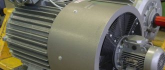
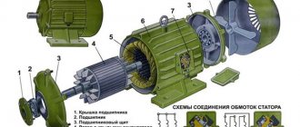
Every electric motor has two important working parts: the rotor and the stator. They are enclosed in a protective casing. To cool the winding conductors, a fan is installed on the rotor shaft. This is the general principle of the structure of all types of electric motors.
The designs of the stators of the electric motors under consideration are no different from the structure of these parts in other types of electric motors operating in alternating current networks. The stator cores, designed to operate at three-phase voltage, are arranged in a circle at an angle of 120º. Windings of insulated copper wire of a certain cross-section are installed on them, which are connected by a triangle or star. The design of the stator magnetic circuit is rigidly mounted on the walls of the cylindrical housing.
The structure of the electric motor is clear from Figure 1. Pay attention to the design of the windings without a core in a squirrel-cage rotor.
Rice. 1. Structure of an asynchronous motor with a short-circuit rotor
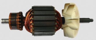
The rotor is designed a little differently. The design of its winding is very similar to a squirrel cage. It consists of aluminum rods, the ends of which are closed by short-circuiting rings. In high-power motors, you can see the use of copper rods as short-circuited rotor windings. This metal has low resistivity, but is more expensive than aluminum. In addition, copper melts faster, and this is not desirable, since eddy currents can greatly heat the core.
Structurally, the rods are located on top of the rotor cores, which consist of transformer steel. When manufacturing rotors, the cores are mounted on the shaft, and the winding conductors are pressed (poured) into the grooves of the magnetic core. In this case, there is no need to insulate the core grooves. Figure 2 shows a photo of a rotor with short-circuit windings.
Rice. 2. Rotor of an asynchronous motor with short-circuit windings
The magnetic core plates of such rotors do not require varnish insulation of surfaces. They are very simple to manufacture, which reduces the cost of asynchronous electric motors, the share of which is up to 90% of the total number of electric motors.
The rotor rotates asynchronously inside the stator. Minimum distances in the form of air gaps are established between these parts. The optimal gap is between 0.5 mm and 2 mm.
Depending on the number of phases used, asynchronous electric motors can be divided into three types:
They differ in the number and location of stator windings. Models with three-phase windings are characterized by high operating stability at rated load. They have better starting characteristics. Often such electric motors use a simple starting circuit.
Two-phase motors have two stator windings arranged perpendicularly, each receiving alternating current. They are often used in single-phase networks - one winding is connected directly to the phase, and a phase-shifting capacitor is used to power the second. Without this part, the rotation of the asynchronous electric motor shaft will not begin on its own. Due to the fact that the capacitor is an integral part of a two-phase electric motor, such motors are also called capacitor motors.
In the design of a single-phase electric motor, only one working winding is used. To start rotor rotation, a starting inductor is used, which is briefly connected to the network through a capacitor or short-circuited. These low-power motors are used as electric drives for some household appliances.
Low-power analogues
Research on three-phase asynchronous motors suggests that this type is the most efficient in most situations. However, there are also single- and two-phase motors. A single-phase operating circuit implies the presence of only one winding on the stator, which receives power in the form of alternating voltage. In this case, the stator is equipped with a special starting winding, which receives a starting pulse through a capacitor or using inductance. Some models produce a momentary short circuit. This is done to create a phase shift; without it, the rotor will not start rotating due to the pulsation of the stator magnetic field.
Single-phase electric motors, the asynchronous systems of which use magnetic fields, are also equipped with rotors in the form of a cylinder with grooves filled with aluminum and cooling blades monolithically connected to it. This rotor design is called squirrel-cage; Sometimes you can find the designation “squirrel cage”. The scope of application of single-phase motors is low-power household equipment.
If only a single-phase alternating power supply network is available, it would be rational to use a two-phase motor. These units also have a stator with two perpendicular windings. One winding is directly connected to the power supply network, and a capacitor is installed in front of the second winding, providing a phase shift. This circuit allows you to set the rotation of the magnetic field and ultimately start the electric motor.
Two-phase motors have more capabilities than single-phase motors. Therefore, their field of operation is household and industrial equipment with low and medium loads. Another name for two-phase units is capacitor; this is due to the presence of a capacitor, the main component that allows the rotor to move.
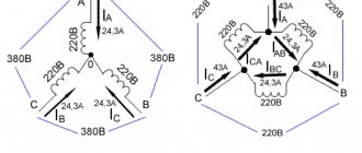
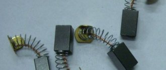
Connection
The stator windings of a three-phase ADKR can be connected in a “delta” or “star” circuit. In this case, the sprocket requires a higher voltage than the triangle.
Please note that an electric motor connected in different ways to the same network consumes different power. Therefore, you cannot connect an electric motor designed for a star circuit according to the delta principle. But in order to reduce starting currents, you can switch the star-delta contacts during the start-up, but then the starting torque will also decrease.
The connection diagrams are clear from Figure 4.
Rice. 4. Connection diagrams
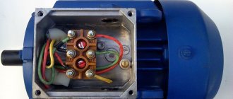
To connect a three-phase electric motor to a single-phase current, phase-shifting elements are used: capacitors, resistors. For examples of such connections, see Figure 5. You can use either a star or a triangle.
Rice. 5. Examples of connection diagrams for a single-phase network
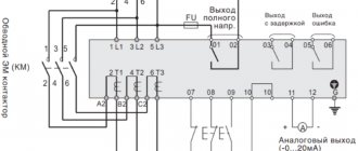
In order to control the operation of the motor, additional devices are connected to the stator electrical circuit.
Calculation of IAD with a squirrel cage rotor
Guidelines for calculation and practical work
in the course “Calculation of elements and devices of control systems”
and to complete the relevant sections
diploma design for students of specialty 210100
Balakovo Institute of Technology,
technology and management
Purpose of the work: to become familiar with the basics of calculating asynchronous actuator motors
Basic Requirements Analysis
Controlled AC motors have a number of specific requirements that must be taken into account during design. The most important of these requirements are: the absence of self-propelled guns; sufficient linearity of mechanical characteristics (
); obtaining a small starting torque per watt of power consumption; a sufficiently small value of the electromechanical time constant (
msec); minimum starting voltage (
); Possibility of long-term operation in starting mode (short circuit).
Energy indicators of engine operation: useful shaft power, efficiency,
- are taken into account following the above requirements. All other things being equal, they strive to maximize them, which in some cases determines the choice of the rotor of the controlled motor, the number of pole pairs, and the frequency of the supply voltage.
It should be noted that simultaneous fulfillment of all the above requirements and obtaining high energy performance of the engine in nominal mode is impossible. Usually you have to look for a reasonable compromise solution that satisfies the most important requirements for a given engine type. For example, the requirements for the absence of self-propelling and a low degree of nonlinearity of the mechanical characteristics force me to fulfill the requirements of a motor with a high active rotor resistance. Naturally, in this case the efficiency and the net power of the engine turns out to be significantly lower than that of similar asynchronous motors for general use. To obtain the minimum starting voltage, the motor must have the smallest number of pole pairs p
and a complete non-magnetic rotor, which is not always consistent with the optimal values of other characteristics.
Squirrel wheel
Squirrel wheel
- a toy for domestic animals, usually small rodents (squirrels, mice, hamsters, chipmunks, etc.), which is a wheel within which the animal moves. Can also be used as a temporary cage for transferring an animal.
The design itself is a rotating wheel with a fixed axis of rotation and assumes that the animal can run in it for quite a long time (until it gets tired), but does not run away anywhere. Hence also the expression “Spinning (spinning) like a squirrel in a wheel
" The outline of the rotating wheel can be either lattice or solid with small protrusions. The distance between the rods (protrusions) is selected taking into account the anatomical features of a particular animal species.
It is an effective exercise machine for maintaining the physical tone of small pets.
There are also similar attractions for children and adults. In this case, both in a stationary version (the axis of rotation is fixed) and in a moving version (the axis of rotation is not fixed).
"Squirrel wheel" in electrical engineering
“Squirrel wheel” is a method of connecting electrical conductors in the rotor of an AC induction motor. Invented in 1889 by M. O. Dolivo-Dobrovolsky (German patent No. 51083 dated March 8, 1889 under the name “Anker für Wechselstrommotoren”). Outwardly it looks like a toy in which pets run.
see also
- A walking ball is a similar toy for small pets.
- A treadmill is a sports machine with a similar operating principle - an endless track that allows the runner to remain in place relative to the room.
| This is a draft article on zoology. You can help the project by adding to it. |
Write a review about the article “Squirrel Wheel”
Traveling magnetic field
The stator of asynchronous motors connected to a three-phase network consists of three electromagnets. They are supplied with voltage from different phases of the network. And since different phases work - increase and decrease - with a time shift from each other, the magnetic field in the coils will similarly increase and decrease. First, the field will arise and grow in the coil of phase 1, after one third of the period the field in the second phase will arise and increase in the same way, and the field in the first phase will gradually and smoothly, along a sinusoid, first stop increasing and then begin to decrease. Everything will be repeated for the coil of the third phase - the field will appear and increase, while the field in the second will first stop its growth and then begin to decline. And at this time the field in the first phase will already reach zero and will increase in the negative direction.
Three-phase motor structure
| Three-phase asynchronous motors, section 1 – rotor shaft (steel); 2 – stator winding (enameled copper wire); 3 – stator core (electrical steel, alloy of iron and silicon); 4 – rotor conductors (aluminum); 5 – rotor core (electric steel); 6 – fan impeller (aluminum); 7 – cast engine housing (steel) | Formation of a magnetic field vector running in a circle On each stator phase coil, from a three-phase voltage varying sinusoidally with a shift of each phase relative to the other by 120°, such an induction force arises that the resulting magnetic field direction vector begins to run in a circle with an angular velocity equal to the voltage frequency in a three-phase network |
If you make only three windings in the stator, according to the number of phases in the supply voltage, then the magnetic field will rotate at the same frequency as the voltage, that is, 50 times per second. But in practice they do much more.
Field in the stator
Then the field running in a circle will have a lower rotation frequency, but the rotation will become smoother.
Single-phase and three-phase asynchronous motors
We agreed - three-phase commutator motors are difficult to obtain; the current section deals with asynchronous machines. We list the varieties:
- Three-phase asynchronous motors are equipped with a number of outputs from three to six working windings minus various fuses, internal relays, and various sensors. The stator coils inside are connected by a star, making it impossible to directly connect to a single-phase network.
- Single-phase motors equipped with a starting winding are, among other things, equipped with a pair of contacts leading to a centrifugal limit switch. The miniature device breaks the chain when the shaft is untwisted. The starting winding catalyzes the initial stage. Further action will interfere, reducing the efficiency of the engine. The design is usually called bifilar. The starting winding is wound with double wire, reducing reactance. Helps reduce the capacitance of the capacitor - critical. A striking example of single-phase asynchronous motors with a starting winding are the compressors of household refrigerators.
- The capacitor winding, different from the starting winding, operates continuously. We will find the motors inside the floor fans. The capacitor provides a phase shift of 90 degrees, allowing you to choose the direction of rotation and maintain the desired shape of the electromagnetic field inside the rotor. Typically the capacitor is mounted on the motor housing.
- Small asynchronous motors used in hoods and fans can be started without a capacitor at all. The initial movement is formed by the flapping of the blades, or by the curvature of the rotor wiring (grooves) in the desired direction.
Let's learn how to distinguish single-phase asynchronous motors from three-phase ones. In the latter case, there are always three equal windings inside. Therefore, you can find three pairs of contacts that, when examined by a tester, give the same resistance. For example, 9 ohms. If the windings are connected by a star inside, there will be three terminals with the same resistance. Of these, any pair gives identical readings displayed on the multimeter screen. The resistance is equal to two windings each time.
Because current must flow out, sometimes a three-phase motor has a neutral terminal. The center of the star, with each of the other three wires, gives identical resistance, half that shown by the pairwise continuity. The above symptoms speak eloquently: the motor is three-phase, alien to the topic of today’s conversation.
The winding motors discussed in this section contain two. One starting or capacitor (auxiliary). There are usually three or four conclusions. If there is no capacitor decorating the case, you can try to reason, puzzled by the purpose of the contacts, as follows:
- There are four pins - you need to measure the resistance. Usually they ring in pairs. The resistance is lower - we found the main winding, connected to a 230 volt network without a capacitor. Polarity does not matter; the direction of rotation is set by the way the auxiliary winding is turned on, by switching the coils. Simply put, connect a single-phase electric motor of a characteristic type with only one main winding - in the initial period of time the shaft stands upright. Wherever you spin, there will be rotation. Beware of starting with your hand - it will break.
- We see three conclusions. Inside, the ends of the coils are connected to form a star. Neutral (circuit zero) is supplied. Regarding the other two terminals, the pairwise resistance will be the greatest (equal to both windings connected in series). The smallest value, as before, will be the working winding; the starting phase passes through the capacitor. Will provide a shift in the right direction. Typically, such a motor rotates unidirectionally; it is impossible to physically change the polarity of the capacitor. However, there is information (we’ll check the diagrams another time): by feeding the working coil with voltage through a capacitor, turning on the starting coil directly, we will perform a reverse. The possibility of connecting a 3-wire electric motor, implementing reverse rotation, is not mentioned in the literature.
Advantages and disadvantages
The widespread use of asynchronous motors with squirrel cage rotors is due to their undeniable advantages:
- stability of operation at optimal loads;
- high operational reliability;
- low operating costs;
- durability of operation without maintenance;
- relatively high efficiency indicators;
- low cost compared to models based on wound rotors and other types of electric motors.
Disadvantages include:
- high starting currents;
- sensitivity to voltage changes;
- low slip coefficients;
- the need to use devices such as frequency converters, starting rheostats, etc., to improve the characteristics of the electric motor;
- Electric motors with a squirrel-cage rotor require additional switching control devices in cases where there is a need to regulate the speed.
Electric motors of this type have decent mechanical characteristics. Despite their shortcomings, they are leaders in terms of their application rates.
Motor with permanent magnets PM
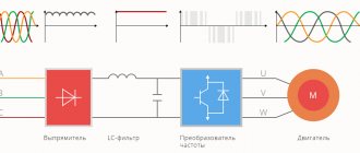
The permanent magnet (PM) synchronous motor is an innovative motor in terms of electric motor technology, combining the highest precision control of conventional speed of a synchronous motor with the simple design and reliability of a squirrel cage induction motor. Mechanically, the PM motor is similar to a traditional induction motor , however, in terms of performance it can achieve superior results . PM motors of the “6S4 – 7S4” series consist of two rotors with permanent magnets generating a constant magnetic field; the rotor rotates at the same speed of the magnetic field generated by the stator winding, regardless of the torque required by the shaft, however, in general, the asynchronous motor exhibits slip proportional to the torque developed moment. Consequently, there are no leaks associated with rotor magnetization , which translates into less electrical energy to produce mechanical energy and less heating of the motor itself. Consequently, synchronism improves dynamic performance , providing constant torque over a wide range, high performance even at low frequencies (the efficiency level is much higher than that of asynchronous motors) and without the need for forced ventilation; a constant torque at different rotation speeds leads to a simplification of the kinematic chain, with all the advantages arising from their operation. Permanent magnetic motors are used in various sectors . This is especially beneficial where weight, frame dimensions and maintenance costs are concerned . In sequence, they are well suited for installation in pumping systems, HVAC ventilation and transmission compressors and elevators, as well as in many types of industrial equipment, such as textiles, metallurgy and paper and pulp. The most significant design advantages are: • High efficiency • High performance across the entire speed range, especially at low speeds where efficiency is higher than that of induction motors. • Reduced rotor losses • Constant torque across the entire speed range • High power density • Precise speed control even without an encoder • Reduced overheating , leading to longer life of insulation, bearings and other motor components • Reduced overall dimensions and weight of the motor • Fast payback Motors PMs with a permanent magnet can only be operated using an inverter. Elvem can supply its own customers with complete systems: PM motors with integrated or separate inverter.
ELVEM SRL
Via delle Industry, 42
36050 Cartigliano – Vicenza – Italy
Tel: +39 0424 513972/ +39 0424 35410
Fax: +39 0424 35405
SUBSCRIBE TO NEWSLETTER
Certificates
Privacy Overview
Necessary cookies are absolutely essential for the website to function properly. This category only includes cookies that ensures basic functionalities and security features of the website. These cookies do not store any personal information.
Soldering copper rods
If cracks are detected on parts of the rods protruding from the active steel, measures are taken to eliminate them. If the depth of the crack does not exceed approximately a quarter of the thickness of the rod, then it is welded by first cutting out a recess in this place by an amount greater than the size of the crack.
Rice. 4. Soldering a copper rod : 1 - short-circuiting ring: 2 - insert; 3 - rod If the crack is deeper, then the rod is cut and the section soldered to the short-circuit ring is removed by drilling. Through the hole formed in the short-circuiting ring at the end of the part of the rod remaining in the groove, a hole is drilled to a depth of 6-7 mm. The diameter of this hole should not exceed half the diameter of the rod. In place of the removed part of the rod, an insert is installed and soldered (Fig. 4), made of copper grades Ml and M2. In this case, the one-sided radial gap a between the rod and the short-circuit ring and between the ends of the repaired rod and insert should be equal to: 0.2 mm when soldering with MF-9 copper-phosphorus solder; 0.1-0.15 mm - silver-containing solders. The choice of solder brand is determined by operating conditions (heavy starting) and peripheral speed. At a peripheral speed of 50 m/s or more, PsR-45 solder is used. For engines operating in lighter conditions - MF-9 solder. Before soldering, the closing rings are degreased and etched. Local degreasing is carried out with a clean rag soaked in a fireproof cleaning liquid, repeating this operation 3-4 times. Etching is carried out for 15-30 s in a solution of concentrated nitric acid containing 250-350 g/l at a temperature of 20°C. The etched areas are washed with hot water, wiped with a dry, clean cloth and dried. Soldering is performed with an oxygen-acetylene flame using burner No. 4 or 5. Soldering should be performed no later than 8 hours after etching. Borax or flux No. 209 is used as a flux. When performing soldering, the temperature of the rod and short-circuit ring is maintained with the second torch even after they have been heated. Solder is melted by touching the hottest areas. Do not allow the solder to melt in the burner flame. Flux is applied to the surfaces to be soldered using a heated solder rod. Soldering of the insert with a short-circuiting ring is performed with the rotor in a vertical position. After soldering, clean and file the joints and check the quality of the soldering with a magnifying glass. After repair, the rotor is balanced. Repair of aluminum rods and short-circuit rings. Areas with cracks are cut as shown in Fig. 5. Before welding, the cut areas and adjacent areas 30-40 mm wide are subjected to mechanical cleaning with preliminary and subsequent degreasing.
Squirrel cage. Design of an asynchronous squirrel-cage electric motor
Asynchronous brushless motors are most widely used due to their comparative simplicity and reliability in operation. Commutator motors have limited use in installations where it is necessary to regulate the speed of driven mechanisms over a wide range. However, they are relatively heavy, expensive, have worse performance characteristics compared to brushless motors, and most importantly, are less reliable in operation due to difficult current switching conditions. Asynchronous brushless machines have two main designs: with a short-circuited rotor winding and with a phase rotor winding - with slip rings. From the point of view of the electromagnetic processes occurring in an asynchronous motor, two most important parts can be distinguished: a stationary stator, which ensures the creation of a rotating magnetic field, and a rotating rotor, in which an electromagnetic torque is created, transmitted to the driven mechanism. The stator cores are made from sheets of electrical steel 0.5 mm thick and less often 0.35 mm thick, insulated from each other with a varnish coating (in the rotor cores of low-power engines, the insulation is a layer of scale on the surface of the sheet). Special grooves are made in the stator and rotor cores in which the corresponding windings are placed.
Rice. 1. Cast aluminum squirrel cage rotor of a squirrel-cage induction motor (with a short-circuit ring and ventilation blades) One of the most common rotor windings is a squirrel cage, the so-called squirrel cage (outwardly it resembles a squirrel wheel - Fig. 1). The working wires of this winding (rods) are laid uninsulated in the grooves of the rotor, which ensures good use of the groove area and good heat transfer from the rods to the active steel. Squirrel-cage asynchronous motors have the following modifications according to the rotor design: with a single squirrel cage; deep groove; with a double squirrel cage, or two-cage. The structural difference between these modifications determines the difference in the characteristics of these machines, primarily the launch ones. Rice. 2. Grooves and rods of the rotor windings. a - single squirrel cage; b—deep groove; c - double squirrel cage. Asynchronous motors with a single squirrel cage on the rotor have grooves stamped into oval or round sheet steel (Fig. 2a). From above these grooves are covered with a bridge 0.4-0.5 mm thick and filled with aluminum. At both ends of the rotor there are aluminum rings that close all the rods cast in the grooves. Such a cast single squirrel cage is often additionally equipped with special aluminum wings on both sides of the rotor (see Fig. 1). These wings are installed to increase heat dissipation from the squirrel-cage rotor and for better ventilation inside the asynchronous machine. In asynchronous electric motors with a deep-slotted rotor (Fig. 2, b), the squirrel cage is usually made of copper rods of rectangular cross-section. Short-circuit rings at the ends of the rotor, as a rule, are also made of copper, in which slots are milled in accordance with the dimensions of the rectangular rods. The rods and rings are soldered to each other with refractory solders. The two-cage rotor (Fig. 1,c) is made with two squirrel cages. The outer winding is made of brass or special bronze, which ensures its relatively high active resistance and relatively low inductive resistance. This winding performs the starting function in an asynchronous motor. The other rotor winding, the internal winding, is made of copper with minimal active resistance. It performs the functions of the main working winding of the motor. Both windings have round grooves, but the inner winding in some cases is rectangular or oval. The shorting end rings for both windings are usually made of copper. There are other modifications of the rotor slots (bottle profile, trapezoidal profile), however, those described above are most typical for asynchronous motors. In an asynchronous motor, the rotation speed of the rotor, entrained by the magnetic field of the stator, is less than the rotation speed of the field itself. In fact, if these frequencies were equal, the movement of the field relative to the rotor would cease, since the electromotive force would cease to be induced in the rotor, creating currents in its windings. In this case, the interaction of the rotor with the rotating field would cease and the cause of rotation of the rotor would be eliminated. In this case, the rotor would inevitably begin to slip, i.e., its rotation frequency would become less than the rotation frequency of the magnetic field, which corresponds to the actual position in an asynchronous motor. Due to the difference in the rotation frequencies of the field and the rotor, the machines under consideration are called asynchronous. When studying the phenomena occurring in the rotor of an asynchronous motor when it is braked (i.e., with a stationary rotor), we can conclude that the machine in this mode, by its physical nature, is a transformer. The primary winding of the transformer is the stator, and the secondary winding is the rotor winding. In general, an asynchronous motor differs from a transformer mainly in its design. In an asynchronous machine, the secondary winding is separated from the primary winding by an air gap, which is not the case in general industrial transformers. In addition, the secondary winding of the motor rotates relative to the primary. As noted above, the rotational speed n at which the rotor rotates must differ from the rotational frequency of the magnetic field n1. Depending on the ratio of these frequencies, there are three modes of operation of an asynchronous machine: motor, generator, brake. When an asynchronous machine operates in motor mode, the rotor speed changes within 0p1), then the asynchronous machine will switch to generator mode. In this case, the direction of rotation of the stator field relative to the rotor will change to the opposite compared to the operation of the machine in motor mode. The electromagnetic torque on the shaft, developed by an asynchronous machine, becomes braking in relation to the motor, which causes it to rotate. The mechanical energy transmitted by this motor to the asynchronous machine is converted into electrical energy and sent to the network to which its stator is connected. The operating mode of an asynchronous machine, when the rotor is driven against the direction of rotation of the electromagnetic field of the stator, is called the electromagnetic brake mode. ?
Transformer substations of the highest quality
energy comes with us
[email protected]
Squirrel cage type windings
1. Design. Squirrel cage-type squirrel-cage windings include the rotor windings of squirrel-cage asynchronous motors, damper (quiescent) windings of synchronous generators and starting windings of synchronous motors. The winding is formed from rods closed on both sides by a short circuit and rings. In asynchronous machines, an equal-pitch, or full, squirrel cage is used, in which the distances between adjacent rods are the same (Fig. 16-23). In synchronous machines (salient poles), an unequal pitch, or incomplete, squirrel cage is used, the rods of which are located, as a rule, only in the pole piece and are absent in the interpolar space (Fig. 16-24). The squirrel cages of the rotors of asynchronous motors with a power of up to 200 kW (in some cases - up to 400 kW) are made of cast aluminum (Fig. 16-23). » Pure primary aluminum is used to fill the rotors of general purpose electric motors. The chemical composition of the cast squirrel cage must correspond to the composition of primary aluminum grade A5 or A6 (no more than 0.5% impurities). Cast squirrel cages are technologically advanced and reliable. Squirrel cages with a diameter of up to 550 mm and a length of up to 700 mm are produced using the casting method. Cast squirrel cages are used, in particular, in electric motors of the single series A, AO, A2, AO2 up to size 11. The rods of cast squirrel cages are located in closed or semi-closed grooves of various shapes (deep with parallel walls, deep trapezoidal, wedge-shaped, scapular - Fig. 16-25, a-d). The short-circuited windings of large induction motors (with a power of approximately over 200 kW) and salient-pole synchronous machines are welded, usually from copper or brass rods and copper (brass, sometimes steel) short-circuit rings or segments. Welded short-circuited windings of asynchronous motors can have rods of round, rectangular (deep groove, Fig. 16-25, f) or special (flask-shaped, wedge-shaped - Fig. 16-25, e, g) profile; double squirrel cages are also used, when the rods of both windings are located in semi-closed grooves at different depths (Fig. 16-25, h). In asynchronous motors with a double squirrel cage, usually the rods of the working (inner) cage are copper, and the starting (external) cage is brass (less often, bronze). Large asynchronous motors of the A and A3 series produced by domestic industry (power from 200 to 1,250 kW) have a squirrel cage with rods of a predominantly flask-shaped profile. The squirrel cage rods of synchronous machines usually have a circular cross-section and are made of copper or brass. The rods are located in the grooves of the pole pieces. The rods of each pole are soldered on both sides to the segments, the segments of adjacent poles are connected to each other with bolts (Figure 16-24). The connection of rods with short-circuiting rings (segments) in welded squirrel cages is carried out by soldering with hard solders (mainly grades PSr-15, PSr-45 and PMF-7) using a gas welding torch.
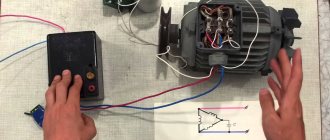
How to check the engine before starting
Before putting an asynchronous motor into operation, it is advisable to check its functionality. Where to start?
External inspection of the engine. Check for chips, dents, and rotate the motor shaft. It should spin smoothly and without jerking in both directions. With this action you check the bearings that hold the engine rotor. If the motor shaft jams, there may be several reasons for this: the bearing seats are broken, the bearings are dead, or the rotor is rubbing the stator. In order to find out the reason, you will need to completely disassemble the engine and find out the real problem. If everything is ok, then we move on to the next step.
Checking the motor windings . To do this, take a multimeter, set it to measure resistance and check the resistance of the windings. If the windings are connected in a star configuration, then it will be enough for us to measure the resistance between the terminals where the supply voltage is supplied. This is done in three stages.
Once.
Two.
Three.
In all three cases the resistance should be the same . A deviation of several ohms is allowed.
With these three steps we checked the windings of our motor and made sure that they were all intact.
And the final step. We check whether the windings are ringing to the ground. Since all the windings are connected to each other in one way or another, it will be enough to place a multimeter probe on any of the windings, and place the second probe on the motor housing. Set the switch on the multimeter to measure MOhm.
Ideally, you should get an infinitely large resistance, in reality from 100 MOhm and higher. If the resistance is very small, something around 1-10 Ohms, then this means that one of the motor windings is ringing to ground, which is absolutely unacceptable. In practice, if the resistance is less than 1 MOhm, then it is necessary to find out the cause and eliminate it. Most likely, moisture, dirt got into the engine, or a breakdown of the dielectric of the copper wire occurred. In this case, only complete disassembly and visual identification of the cause will help.
All the same operations apply to a motor with a delta connection diagram.
Most of the material for the article “Induction Motor” was taken from the video below. A must watch.