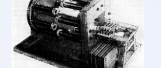
It is often necessary to reduce the rotation speed of a motor that performs certain tasks in a mechanism. Reducing the speed of an electric motor can be achieved using homemade devices and standard-made control circuits.
AC electric motors are often used in human activities, on metalworking machines, transport, crane mechanisms and other equipment. Motors convert alternating current energy into rotation of the shaft and components. Mainly asynchronous AC motors are used.
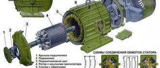
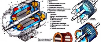
The rotor, as well as the stator of the motor, consists of coils of wire placed in a core made of special steel. The classification of electric motors follows from the method of laying the winding.
A winding of brass and copper rods is inserted into the core, and rings are installed along the edges. Such a coil of wire is called a short-circuited (SC) rotor. Small power electric motors have rods as well as discs that have been cast together. For electric motors with high torque, the parts are cast separately and then welded. The stator winding can be connected in two ways: triangle, star.
The phase rotor consists of a 3-phase rotor winding connected by slip rings and brushes to the power supply. The winding is star connected.
What is an asynchronous motor?
AC electric motors have found quite wide application in various spheres of our life, in hoisting, processing, and measuring equipment. They are used to convert electrical energy that comes from the network into mechanical energy of a rotating shaft. Most often, asynchronous AC converters are used. In them, the rotation speed of the rotor and stator is different. A structural air gap is provided between these active elements.
Both the stator and the rotor have a rigid core made of electrical steel (composited type, made of plates), acting as a magnetic circuit, as well as a winding that fits into the structural grooves of the core. It is the way in which the rotor winding is organized or laid out that is the key criterion for classifying these machines.
Squirrel-cage motors (SCR)
Here, a winding is used in the form of aluminum, copper or brass rods, which are inserted into the grooves of the core and closed on both sides by disks (rings). The type of connection of these elements depends on the engine power: for small values, the method of joint casting of disks and rods is used, and for large values, separate production is used, followed by welding to each other. The stator winding is connected using delta or star circuits.
Wound rotor motors
The three-phase rotor winding is connected to the network via slip rings on the main shaft and brushes. The “star” scheme is taken as the basis. The figure below shows a typical design of such an engine.
DC motors
In addition to AC machines, there are electric motors connected to a DC network. The speed of such devices is calculated using completely different formulas.
Rated rotation speed
The speed of a DC machine is calculated using the formula in the figure below, where:
- n – number of revolutions per minute,
- U – network voltage,
- Rya and Iya – armature resistance and current,
- Ce – motor constant (depending on the type of electric machine),
- Ф – stator magnetic field.
These data correspond to the nominal values of the parameters of the electric machine, the voltage on the field winding and the armature or the torque on the motor shaft. Changing them allows you to adjust the rotation speed. It is very difficult to determine the magnetic flux in a real motor, so calculations are made using the current flowing through the field winding or armature voltage.
Formula for calculating the speed of a DC motor
The speed of commutator AC motors can be found using the same formula.
Operating principle and speed of asynchronous motors
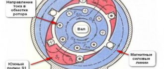
Let's consider this issue using the example of ADKR, as the most common type of electric motors in lifting, transport and processing equipment. The mains voltage is supplied to the stator winding, each of the three phases of which is geometrically displaced by 120°. After applying voltage, a magnetic field arises, which creates, by induction, an emf and a current in the rotor windings. The latter causes electromagnetic forces that cause the rotor to rotate. Another reason why all this happens, namely, EMF occurs, is the difference in the speed of the stator and rotor.
One of the key characteristics of any ADCR is the rotation speed, which can be calculated using the following relationship:
n=60f/p, rpm
where f is the frequency of the mains voltage, Hz; p – number of stator pole pairs.
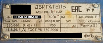
All technical characteristics are indicated on a metal plate attached to the body. But if it is missing for some reason, then the number of revolutions must be determined manually using indirect indicators. Typically, three main methods are used:
- Calculation of revolutions taking into account the diametric pitch of the winding. To determine, a formula of the form is used:
where 2p – number of poles; Z1 – number of slots in the stator core; y – actually, the step of laying the winding.
Standard speed values:
- Calculation of the number of poles along the stator core. Mathematical formulas are used, which take into account the geometric parameters of the product:
2p = 0.35Z1b/h or 2p = 0.5Di/h,
where 2p – number of poles; Z1 – number of slots in the stator; b – tooth width, cm; h – backrest height, cm; Di is the internal diameter formed by the teeth of the core, cm.
After this, based on the data obtained and magnetic induction, it is necessary to determine the number of turns, which is checked against the motors’ passport data.
Ways to change engine speed
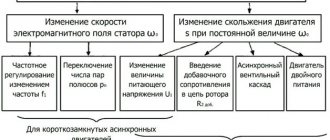
Adjusting the speed of any three-phase electric motor used in lifting and transport machinery and equipment allows you to achieve the required operating modes accurately and smoothly, which is not always possible, for example, due to mechanical gearboxes. In practice, seven main methods of rotation speed correction are used, which are divided into two key areas:
- Change in the speed of the magnetic field in the stator. Achieved by frequency regulation, switching the number of pole pairs or voltage correction. It should be added that these methods are applicable to electric motors with squirrel-cage rotor;
- Changing the amount of slip. This parameter can be adjusted by using the supply voltage, connecting additional resistance to the electrical circuit of the rotor, using a valve cascade or dual power supply. Used for models with wound rotor.
The most popular methods are voltage and frequency regulation (through the use of converters), as well as changing the number of pole pairs (implemented by organizing an additional winding with switching capability).
Typical speed controller circuits
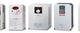
There is a wide selection of regulators and frequency converters for asynchronous motors on the market today. However, for the domestic needs of lifting or processing equipment, it is quite possible to calculate and assemble a homemade device on a microcircuit based on thyristors or powerful transistors.
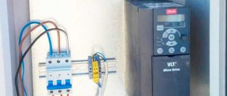
Below is an example of a circuit of a fairly powerful regulator for an asynchronous motor. Due to this, you can achieve smooth control of its operating parameters, reduce energy consumption by up to 50%, and reduce maintenance costs.
This scheme is complex. For domestic needs, it can be significantly simplified by using a triac, for example, VT138-600, as a working element. In this case, the diagram will look like this:
The motor speed will be regulated by a potentiometer, which determines the phase of the input pulse that opens the triac.
As can be judged from the information presented above, not only its operating parameters, but also the efficiency of the powered lifting or processing equipment depend on the speed of an asynchronous motor. Today you can purchase a wide variety of regulators in the retail chain, but you can also make calculations and assemble an effective device with your own hands.
Single-phase asynchronous motors are powered from a conventional 220 V alternating voltage network.
The most common design of such motors contains two (or more) windings - working and phase-shifting. The working one is fed directly, and the additional one is fed through a capacitor, which shifts the phase by 90 degrees, which creates a rotating magnetic field. Therefore, such motors are also called two-phase or capacitor motors.
It is necessary to regulate the rotation speed of such motors, for example, for:
- changes in air flow in the ventilation system
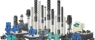
- pump performance control
- changes in the speed of moving parts, for example in machine tools, conveyors
In ventilation systems, this allows you to save energy, reduce the level of acoustic noise of the installation, and set the required performance.
Methods of regulation
We will not consider mechanical methods of changing the rotation speed, for example gearboxes, couplings, gear transmissions. We will also not touch upon the method of changing the number of poles of the windings.
Let's consider methods with changing electrical parameters:
- change in motor supply voltage
- change in supply voltage frequency
How to maintain frequency converters?
For long-term operation of the inverter, it is necessary to monitor its condition and follow the maintenance instructions:
- Clean internal elements from dust. You can use a compressor to remove dust with compressed air. A vacuum cleaner is not suitable for these purposes.
- Periodically monitor the condition of the components and replace them. The service life of electrolytic capacitors is five years, fuse links are ten years. Cooling fans last 3 years before replacement. The wire loops have been used for six years.
- Monitoring the DC bus voltage and the temperature of the mechanisms is a necessary measure. At elevated temperatures, the thermal conductive paste dries out and damages the capacitors. Every 3 years, a layer of conductive paste is applied to the power terminals.
- The operating conditions and operating hours must be strictly observed. The ambient temperature should not exceed 40 degrees. Dust and humidity negatively affect the condition of the working elements of the device.
Voltage regulation
Speed control in this way is associated with a change in the so-called engine slip - the difference between the rotation speed of the magnetic field created by the stationary engine stator and its moving rotor:
n1— magnetic field rotation speed
n2 — rotor rotation speed
In this case, sliding energy is necessarily released - which causes the motor windings to heat up more.
This method has a small control range, approximately 2:1, and can also only be carried out downwards - that is, by reducing the supply voltage.
When regulating speed in this way, it is necessary to install oversized motors.
But despite this, this method is used quite often for low-power motors with a fan load.
In practice, various regulator circuits are used for this.
Autotransformer voltage regulation
An autotransformer is an ordinary transformer, but with one winding and taps from some of the turns. In this case, there is no galvanic isolation from the network, but in this case it is not needed, so savings are achieved due to the absence of a secondary winding.
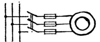
The diagram shows autotransformer T1 , switch SW1 , which receives taps with different voltages, and motor M1.
The adjustment is done in steps; usually no more than 5 steps of regulation are used.
Advantages of this scheme:
- undistorted output voltage waveform (pure sine wave)
- good overload capacity of the transformer
Flaws:
- large mass and dimensions of the transformer (depending on the power of the load motor)
- all the disadvantages inherent in voltage regulation
Thyristor engine speed controller
This circuit uses keys - two thyristors connected back-to-back (the voltage is alternating, so each thyristor passes its own half-wave of voltage) or a triac.
The control circuit regulates the moment of opening and closing of the thyristors relative to the phase transition through zero; accordingly, a piece is “cut off” at the beginning or, less often, at the end of the voltage wave.
This changes the rms voltage value.
This circuit is quite widely used to regulate active loads - incandescent lamps and all kinds of heating devices (so-called dimmers).
Another method of regulation is to skip half-cycles of the voltage wave, but at a network frequency of 50 Hz this will be noticeable for the motor - noise and jerking during operation.
To control motors, regulators are modified due to the characteristics of the inductive load:
- install protective LRC circuits to protect the power switch (capacitors, resistors, chokes)
- add a capacitor at the output to adjust the voltage waveform
- limit the minimum voltage regulation power - for guaranteed engine start
- use thyristors with a current several times higher than the electric motor current
Advantages of thyristor regulators:
Flaws:
- can be used for low power engines
- During operation, noise, crackling, and jerking of the engine may occur.
- when using triacs, a constant voltage is applied to the motor
- all the disadvantages of voltage regulation
It is worth noting that in most modern mid- and high-level air conditioners, the fan speed is adjusted in this way.
Transistor voltage regulator
As the manufacturer himself calls it, an electronic autotransformer or PWM regulator.
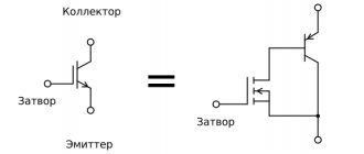
The voltage is changed using the PWM (pulse width modulation) principle, and transistors are used in the output stage - field-effect or bipolar with insulated gate (IGBT).
The output transistors are switched at a high frequency (about 50 kHz); if you change the width of the pulses and pauses between them, the resulting voltage at the load will also change. The shorter the pulse and the longer the pause between them, the lower the resulting voltage and power input.
Inverter selection
Thanks to the lobbying efforts of local power companies, combined with the benefits of variable speed control, variable frequency drives (VFDs) are becoming more common. When using them, special attention should be paid to the generation of electromagnetic interference, which is typical for such drives based on their very nature. In order for an electric motor to be used with a VFD, it is necessary to take into account several technical features that must be met by an otherwise suitable electric motor. Among them, two main ones can be distinguished:
The maximum permissible insulation voltage of the stator winding wires of the electric motor.
The electrical strength of the insulation of the wire from which the stator winding of an asynchronous electric motor is made is in the range of 1000–1600 V, but, as a rule, the documentation indicates an insulation strength value of 1200 V. However, the larger the air gap between the drive and the motor, the naturally , it can withstand larger transient voltage surges affecting the motor. An electric motor that uses wire with a dielectric strength of 1600 V for the stator winding may have a reference to the National Electrical Manufacturers Association (NEMA) standard NEMA MG-1 2003, section 4, paragraph 31, which states that The engine must withstand, without damage, an initial corona inception voltage (CIV) of up to 1600 V.
Frequency regulation
Just recently (10 years ago), there were a limited number of frequency controllers for motor speeds on the market, and they were quite expensive. The reason was that there were no cheap high-voltage power transistors and modules.
But developments in the field of solid-state electronics have made it possible to bring power IGBT modules to the market. As a consequence, there is a massive appearance on the market of inverter air conditioners, welding inverters, and frequency converters.
At the moment, frequency conversion is the main way to regulate the power, performance, speed of all devices and mechanisms driven by an electric motor.
However, frequency converters are designed to control three-phase electric motors.
Single-phase motors can be controlled by:
- specialized single-phase inverters
- three-phase inverters with the exception of the capacitor
Converters for single-phase motors
Currently, only one manufacturer announces serial production of a specialized inverter for capacitor motors - INVERTEK DRIVES.
Optidrive E2 model
For stable engine starting and operation, special algorithms are used.
In this case, frequency adjustment is possible upward, but in a limited frequency range, this is prevented by a capacitor installed in the phase-shifting winding circuit, since its resistance directly depends on the frequency of the current:
f - current frequency
C - capacitance of the capacitor
The output stage uses a bridge circuit with four output IGBT transistors:
Optidrive E2 allows you to control the motor without removing the capacitor from the circuit, that is, without changing the motor design - in some models this is quite difficult to do.
Advantages of a specialized frequency converter:
- intelligent motor control
- Stably stable engine operation
- Huge capabilities of modern inverters:
- the ability to control the operation of the engine to maintain certain characteristics (water pressure, air flow, speed under changing load)
- numerous protections (motor and device itself)
- sensor inputs (digital and analogue)
- various outputs
- communication interface (for control, monitoring)
- preset speeds
- PID controller
Disadvantages of using a single-phase inverter:
Using a state of emergency for three-phase motors
A standard frequency converter has a three-phase voltage at its output. When connecting a single-phase motor to it, remove the capacitor from it and connect it according to the diagram below:
The geometric arrangement of the windings relative to each other in the stator of an asynchronous motor is 90°:
The phase shift of the three-phase voltage is -120°, as a consequence of this - the magnetic field will not be circular, but pulsating and its level will be less than with a power supply with a shift of 90°.
In some capacitor motors, the additional winding is made of thinner wire and therefore has a higher resistance.
When operating without a capacitor, this will lead to:
- stronger heating of the winding (service life is reduced, short circuits and interturn short circuits are possible)
- different current in the windings
Many inverters have protection against current asymmetry in the windings; if it is impossible to disable this function in the device, operation using this circuit will be impossible
Advantages:
- lower cost compared to specialized inverters
- Huge selection of power and manufacturers
- wider frequency control range
- all the advantages of the inverter (inputs/outputs, intelligent operating algorithms, communication interfaces)
Disadvantages of the method:
- the need for preliminary selection of the inverter and motor for joint operation
- pulsating and reduced torque
- increased heating
- no warranty in case of failure, because Three-phase inverters are not designed to work with single-phase motors
Due to their reliability and simplicity of design, asynchronous motors (IM) have become widespread. Most machine tools, industrial and household equipment use electric motors of this type. The rotation speed of the motor is changed mechanically (by additional load on the shaft, ballast, transmission mechanisms, gearboxes, etc.) or electrically. Electrical regulation is more complex, but also much more convenient and versatile.
For many units, electrical control is used. It provides precise and smooth control of engine starting and operation. Electrical control is achieved through:
- changes in current frequency;
- current strength;
- voltage level.
In this article we will look at popular methods of how the speed of an asynchronous motor can be adjusted at 220 and 380V.
How to choose a frequency converter?
If you analyze the prices and functions of frequency converters, you can understand that the price determines the number of built-in functions of the frequency converter. Expensive models have great functionality. But to select a device, it is better to be guided by the required conditions of use.
- Frequency generators come with two types of control: scalar and vector. With scalar control, the device operates at certain values of the output potential difference and frequency; they work in primitive household appliances, for example, fans. With vector control, the current strength is set quite accurately.
- When choosing a device, power parameters play a decisive role. The amount of power expands the scope of use and simplifies maintenance.
- When choosing a device, the operating voltage range of the network is taken into account, which reduces the risk of its failure due to sudden changes in potential difference. If the voltage increases excessively, the network capacitors may explode.
- Frequency is an important factor. Its value is determined by production requirements. The lowest value indicates the possibility of using the speed in the optimal operating mode. To obtain a larger frequency range, frequency generators with vector control are used. In reality, inverters with a frequency range of 10 to 10 Hz are often used.
- A frequency converter that has many different outputs and inputs is convenient to use, but its cost is higher and configuration is more difficult. There are three types of frequency connectors: analog, discrete, digital. Reverse communication of input commands is carried out through analog connectors. Digital terminals input signals from digital type sensors.
- When choosing a frequency converter model, you need to evaluate the control bus. Its characteristics are matched to the inverter circuit, which determines the number of pads. The best choice is a frequency generator with a reserve number of connectors for further modernization of the device.
- Frequency drivers that can withstand heavy overloads (15% higher than the motor power) have preferences when choosing. To avoid making mistakes when purchasing a frequency converter, read the instructions. It contains the main parameters for operating the equipment. If you need a device for maximum loads, then you need to choose a frequency converter that keeps the current at peak operation higher than 10% of the nominal value.
Changing the speed of an IM with a squirrel-cage rotor
There are several ways:
- Rotation control by changing the electromagnetic field of the stator: frequency regulation and changing the number of pole pairs.
- Changing the slip of the electric motor by decreasing or increasing the voltage (can be used for IMs with a wound rotor).
Frequency regulation
In this case, the adjustment is made using a frequency conversion device connected to the engine. For this purpose, powerful thyristor converters are used. The process of frequency regulation can be considered using the example of the EMF formula of a transformer:
This expression means that in order to maintain a constant magnetic flux, which means maintaining the overload capacity of the electric motor, the supply voltage level should be adjusted simultaneously with frequency conversion. If the expression calculated by the formula is saved:
then this means that the critical moment has not been changed. And the mechanical characteristics correspond to the figure below; if you do not understand what these characteristics mean, then in this case the adjustment occurs without loss of power and torque.
Methods for controlling the speed of an IM with a wound rotor
The rotation speed of an IM with a wound rotor is changed by changing the slip. Let's look at the main options and methods.
Changing the supply voltage
This method is also used for IMs with a short-circuit rotor. The asynchronous motor is connected through an autotransformer or LATR. If you reduce the supply voltage, the engine speed will decrease.
But this mode reduces the overload capacity of the engine. This method is used for regulation within a voltage range not higher than the rated voltage, since an increase in the rated voltage will lead to failure of the electric motor.
Active resistance in the rotor circuit
When using this method, a rheostat or a set of high-power constant resistors is connected to the rotor circuit. This device is designed to smoothly increase resistance.
Slip increases in proportion to the increase in resistance, and the rotation speed of the electric motor shaft decreases.
- large range of regulation towards lower rotation speed.
- decrease in efficiency;
- increase in losses;
- deterioration of mechanical characteristics.
Asynchronous valve cascade and dual-fed machines
Changing the operating speed of asynchronous electric motors in these cases is done by changing the slip. In this case, the rotation speed of the electromagnetic field remains unchanged. Voltage is supplied directly to the stator windings. The adjustment occurs through the use of sliding power, which is transformed into the rotor circuit and forms an additional EMF. Such methods are used only in special machines and large industrial devices.
Frequency converter payback
Electricity is constantly becoming more expensive, and managers of organizations are forced to save in different ways. In industrial production, most of the energy is consumed by mechanisms with electric motors.
Manufacturers of devices for electrical machines and units offer special devices and instruments for controlling electric motors. Such devices save electrical energy. They are called inverters or frequency converters.
The financial costs of purchasing a frequency generator do not always justify the cost savings, since their cost is comparable to the cost of saved energy. It is not always possible to quickly equip a mechanism with an inverter. What difficulties arise in this? Let's look at ways to start asynchronous motors to understand the advantages of inverters.
Smooth start of asynchronous electric motors
In addition to unconditional advantages, ADs have significant disadvantages. This is a jerk at the start and high starting currents, 7 times higher than the rated ones. To soft start the electric motor, the following methods are used:
- switching of windings according to the star-delta circuit;
- turning on the electric motor through an autotransformer;
- use of specialized devices for soft starting.
Most frequency controllers have a soft motor start function. This not only reduces inrush currents, but also reduces the load on the actuators. Therefore, frequency regulation and soft starting are quite closely related.
How to connect a frequency converter
If the cable for connection is 220 V with 1st phase, a “triangle” circuit is used. You cannot connect a frequency converter if the output current is higher than 50% of the rated value.
If the power cable is three phase 380 V, then a “star” circuit is made. To make it easier to connect power, contacts and terminals with letter designations are provided.
- Contacts R, S, T are intended for connecting the power supply in phases.
- Terminals U, V, W serve as the motor connection. To reverse, just change the connection of the two wires to each other.
The device must have a block with a ground connection terminal. More details on how to connect are here.
How to make a device for changing the rotation speed of an electric motor with your own hands
Dimmers can be used to regulate low-power single-phase IM. However, this method is unreliable and has serious disadvantages: reduced efficiency, serious overheating of the device and the risk of engine damage.
For reliable and high-quality regulation of the speed of 220V electric motors, frequency regulation is best suited.
The diagram below allows you to assemble a frequency device for adjusting electric motors with a power of up to 500 W. The rotation speed is changed within the range from 1000 to 4000 rpm.
The device consists of a master oscillator with variable frequency, consisting of a multivibrator assembled on a K561LA7 microcircuit, a counter on a K561IE8 microcircuit, and a half-bridge regulator. Output transformer T1 decouples the upper and lower transistors of the half-bridge.
The damping circuit C4, R7 dampens voltage surges that are dangerous for power transistors VT3, VT4. The rectifier, a supply voltage doubler, includes a VD9 diode bridge, with a filter capacitor on which the half-bridge supply voltage is doubled.
Primary winding voltage: 2×12V, secondary winding 12V. The primary winding of the key control transformer consists of 120 turns of copper wire with a cross-section of 0.7 mm, with a tap from the middle. Secondary - two windings, each with 60 turns of a drive with a cross section of 0.7 mm.
The secondary windings must be insulated from each other as reliably as possible, since the potential difference between them reaches 640 V. The output windings are connected to the switch gates in antiphase.
So we looked at ways to adjust the speed of asynchronous motors. If you have any questions, ask them in the comments below the article!