Considering that power supply is traditionally carried out by delivering alternating current to consumers, the desire to create electric machines that operate on supplied electricity is understandable. In particular, alternating current is actively used in asynchronous electric motors, which are widely used in many areas of human activity. The induction motor with a squirrel-cage rotor deserves special attention, which, for a number of reasons, has taken a strong position in application.
The secret of such popularity lies, first of all, in the simplicity of the design and the low cost of its manufacture. Electric motors with squirrel-cage rotors have other advantages, which you will learn about in this article. First, let's look at the design features of this type of electric motor.
Design
Every electric motor has two important working parts: the rotor and the stator. They are enclosed in a protective casing. To cool the winding conductors, a fan is installed on the rotor shaft. This is the general principle of the structure of all types of electric motors.
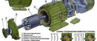
The designs of the stators of the electric motors under consideration are no different from the structure of these parts in other types of electric motors operating in alternating current networks. The stator cores, designed to operate at three-phase voltage, are arranged in a circle at an angle of 120º. Windings of insulated copper wire of a certain cross-section are installed on them, which are connected by a triangle or star. The design of the stator magnetic circuit is rigidly mounted on the walls of the cylindrical housing.
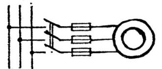
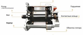
The structure of the electric motor is clear from Figure 1. Pay attention to the design of the windings without a core in a squirrel-cage rotor.
Rice. 1. Structure of an asynchronous motor with a short-circuit rotor
The rotor is designed a little differently. The design of its winding is very similar to a squirrel cage. It consists of aluminum rods, the ends of which are closed by short-circuiting rings. In high-power motors, you can see the use of copper rods as short-circuited rotor windings. This metal has low resistivity, but is more expensive than aluminum. In addition, copper melts faster, and this is not desirable, since eddy currents can greatly heat the core.
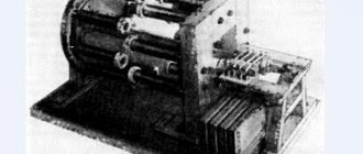
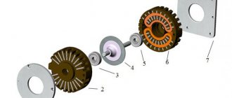
Structurally, the rods are located on top of the rotor cores, which consist of transformer steel. When manufacturing rotors, the cores are mounted on the shaft, and the winding conductors are pressed (poured) into the grooves of the magnetic core. In this case, there is no need to insulate the core grooves. Figure 2 shows a photo of a rotor with short-circuit windings.
Rice. 2. Rotor of an asynchronous motor with short-circuit windings
The magnetic core plates of such rotors do not require varnish insulation of surfaces. They are very simple to manufacture, which reduces the cost of asynchronous electric motors, the share of which is up to 90% of the total number of electric motors.
The rotor rotates asynchronously inside the stator. Minimum distances in the form of air gaps are established between these parts. The optimal gap is between 0.5 mm and 2 mm.
Depending on the number of phases used, asynchronous electric motors can be divided into three types:
- single-phase;
- two-phase;
- three-phase.
They differ in the number and location of stator windings. Models with three-phase windings are characterized by high operating stability at rated load. They have better starting characteristics. Often such electric motors use a simple starting circuit.
Two-phase motors have two stator windings arranged perpendicularly, each receiving alternating current. They are often used in single-phase networks - one winding is connected directly to the phase, and a phase-shifting capacitor is used to power the second. Without this part, the rotation of the asynchronous electric motor shaft will not begin on its own. Due to the fact that the capacitor is an integral part of a two-phase electric motor, such motors are also called capacitor motors.
In the design of a single-phase electric motor, only one working winding is used. To start rotor rotation, a starting inductor is used, which is briefly connected to the network through a capacitor or short-circuited. These low-power motors are used as electric drives for some household appliances.
What are core and iron losses?
In some ways, these costs are divided into eddy current loss and hysteresis. The former can be minimized by using the layers present on the core. Once they are used, the area will be smaller, and the resistance, accordingly, will be higher, thereby reducing the eddy currents.
For example, hysteresis losses can be minimized by using high quality silicon steel. This affects the construction.
The loss of the core depends on what the voltage frequency is. The stator has a frequency of only 50 Hz, and the rotor has an even lower frequency - 1.5 Hz, and all this is due to the fact that under normal operating conditions the slip is no more than 3%. As a result, the losses of the rotor cores are small when compared with the costs of the stator cores. It is precisely by mistake that some people prefer to neglect them in working condition.
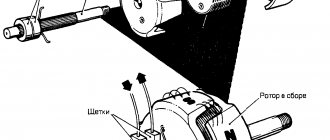
Regarding brush friction losses and mechanical
Induction motors with a wound rotor may experience loss of brush friction. Mechanical loss can be encountered in bearings. At the start, they are all at zero, but as the speed increases, spending will only increase. In three-phase motors, the speed is always constant. We can conclude that this loss will be permanent, and the construction depends on it.
Features of variable losses
This type of loss is also called copper reduction. They can occur due to electric currents passing through the rotor and stator windings. As the load changes, this current will also change along with these reductions. This gave rise to the name variable losses. They are obtained by conducting tests with locked rotors of 3-phase motors.
Important!
The main function of these drives is to convert electrical energy into mechanical energy. During it, the energy will go through several different stages. As it passes through different stages, it will be displayed on a diagram indicating the flow of energy. Everyone knows that at the input of three-phase asynchronous motors the supply is also three-phase. Therefore, it will go to the side of the 3-phase electric motor.
Rotor and Stator
Part of this input energy is used to support the stator deficiencies. And their role is played by the deficiency of stator copper and iron. The energy that is saved will go to the rotor at the input. It already converts these inputs to the rotor into mechanical energy. But this input cannot be converted into the same output, since it maintains a lack of energy on the rotor. When the rotor rotates, the iron consumption will depend on the frequency of the rotor, and it is extremely small. But they prefer to ignore this. So it would be better if the input to the rotor was supported by copper losses.
After energy is created, it will go to the load through the shafts. The appearance of small mechanical costs (air resistance and friction) cannot be avoided. Therefore, the total reproducible energy of a mechanical nature must be supplied to maintain those same losses.
Calculation of mechanical characteristics of asynchronous motors
The natural characteristics of the mechanical design of such motors correspond to the basic (passport) circuits for its connection and the nominal parameters of the supply voltage. But their artificial analogue will be obtained when some of the additional elements are included:
- capacitors;
- reactors;
- resistors.
When the engine is powered by a non-rated voltage, the characteristics will differ from the natural characteristics - they are extremely convenient and useful as a tool when analyzing the static and dynamic modes of electric drives. There are both artificial characteristics of electric motors and natural ones.
Principle of operation
The operation of an asynchronous motor is based on the property of a three-phase current, capable of creating a rotating magnetic field in the stator windings. In the electric motors under consideration, the synchronous rotation frequency of the electromagnetic field is directly proportional to the natural frequency of the alternating current.
There is an inversely proportional dependence of the rotation speed on the number of pole pairs in the stator windings. Considering that the phase shift is 60º, the dependence of the rotor speed (in rpm) can be expressed by the formula:
n1 = (f1*60) / p, where n1 is the synchronous frequency, f1 is the AC frequency, and p is the number of pole pairs.
As a result of the action of magnetic induction on the rotor core, an emf will arise in it, which, in turn, causes the appearance of an electric current in a closed conductor. An Ampere force will arise, under the influence of which the closed loop will begin to rotate in pursuit of the magnetic field. In the nominal operating mode, the rotor rotation speed is slightly behind the rotation speed of the magnetic field created in the stator. When the frequencies coincide, the magnetic flux stops, the current disappears in the rotor windings, as a result of which the force ceases. As soon as the shaft rotation speed lags behind, the action of the ampere force is resumed by alternating currents of magnetic fields.
The difference in the rotation frequencies of the magnetic fields is called the slip frequency: ns=n1–n2, and the relative value s, which characterizes the lag, is called slip.
s = 100% * (ns / n1) = 100% * (n1 - n2) / n1, where ns is the slip frequency; n1, n2 – rotation frequencies of stator and rotor magnetic fields, respectively.
In order to reduce the harmonics of the EMF and smooth out the pulsations of the moment of force, the rods of the short-circuited turns are slightly beveled. Take another look at Fig. 2 and pay attention to the location of the rods that act as rotor windings relative to the axis of rotation.
Slip depends on the mechanical load applied to the motor shaft. In asynchronous electric motors, the sliding parameters change in the range from 0 to 1. Moreover, in idle mode, the rotor that has gained speed experiences almost no active resistance. S approaches zero.
An increase in load contributes to an increase in slip, which can reach unity when the engine stops due to overload. This condition is equivalent to a short circuit and can damage the device.
The relative value of the lag corresponding to the rated load of the electrical machine is called the rated slip. For low-power electric motors and medium-power engines, this figure varies within small limits - from 8% to 2%. When the electric motor rotor is stationary, the slip tends to 0, and when idling it approaches 100%.
When starting an electric motor, its windings are under load, which leads to a sharp increase in starting currents. When the rated power is reached, electric motors with squirrel-cage turns independently restore the rated rotor frequency.
Pay attention to the sliding torque curve shown in Fig. 3.
Rice. 3. Sliding torque curve
As the torque increases, the coefficient s changes from 1 to 0 (see the segment “motor region”). The shaft rotation speed also increases. If the shaft rotation speed exceeds the rated frequency, the torque will become negative and the engine will go into generation mode (the “generating region” segment). In this mode, the rotor will experience magnetic resistance, which will lead to braking of the motor. The oscillatory process will be repeated until the torque stabilizes and the slip approaches the nominal value.
Performance characteristics of three-phase asynchronous motor
Operating characteristics are the dependences of power P
1 slip
s,
current in the stator phase
I
1
, efficiency η
and cosφ1 from useful power
P
2 at
U
1 = const and
f1
= const.
The characteristics are plotted for the zone of practically stable engine operation, i.e. up to slip values (1.1… 1.2)%. The characteristics are experimentally obtained by changing the load on the motor shaft using an auxiliary load device, of which the preferred one is a direct current generator with independent excitation. They directly measure torque, rotation speed, stator current, and power consumed from the network. Slip, efficiency and power factor are determined by calculation using the relationships given above.
Performance characteristics plotted in relative units are presented in Fig. 3.16.
Rice.
3.16. Performance characteristics of a three-phase asynchronous motor Dependence s(P
2
)
is practically linear and the curve is slightly inclined to the abscissa axis, since
s
H
≈
(0.08...0.1) and the moment depends almost linearly on slip.
Dependence P
1
(P
2
)
is also close to linear, as is the dependence I
1
(
P 2
)
.
This indicates that the active component of the current is proportional to the useful power
P
2
.
The reactive component of the current changes little in the range of operating loads, since it is determined by the no-load current
I
0, which is 20...40% of the rated current.
Therefore, the dependence I
1
(P
2
)
does not come from the origin.
Dependence cosφ
1
= f(P
2
)
shows that at low loads cosφ
has low values (0.1...0.3).
With increasing load, cosφ
1 increases, reaching a maximum (0.75...0.9) at a load close to the nominal one.
With increasing load and power, the active component changes little compared to idle mode. With a further increase in load, cosφ
1 decreases due to an increase in the leakage fluxes of the windings.
Dependence η (P
2
)
has the same character as that of a transformer. Maximum efficiency occurs at loads slightly less than the rated value. With a further increase in load, the efficiency decreases due to an increase in electrical losses, which are proportional to the squares of the stator and rotor currents.
From the analysis of performance characteristics it follows that at low loads the operation of the engine is inefficient, it has low efficiency and power factor values. On the other hand, if the engine is overloaded, then its operating efficiency also decreases, but in addition, it experiences increased heating, and cooling conditions, on the contrary, worsen, since the cooling intensity depends on the cube of the fan rotation speed on the engine shaft. Therefore, when choosing an engine for a specific mechanism, you should calculate its power as accurately as possible.
Starting and control methods
Blood pressure rotation frequencies.
The starting properties of asynchronous motors are mainly determined by the following quantities: starting current, starting torque, smoothness and efficiency of the starting process, starting duration. Catalogs usually indicate the starting current multiplicity IP/IN
and starting torque
MP/MN
. In addition, the starting properties of an asynchronous motor are determined by the features of its design, in particular the design of the rotor, which can be with a conventional squirrel-cage winding, with a deep-slot squirrel-cage winding, or with a wound rotor.
There are three types of starting: direct, starting with reduced voltage on the stator, rheostatic starting
(for motors with wound rotor).
Direct start
the simplest and most often used for starting engines with a squirrel-cage rotor. All you need is a switching device - a switch or a magnetic starter, and for a high-voltage motor - an oil switch. Starting occurs by directly connecting the stator winding to the network. When starting a motor directly, the starting current multiplicity is high and amounts to approximately 5.5...7 (for motors with a power of 0.6...100 kW at a synchronous speed of 750...3000 rpm). A short burst of starting current is relatively safe for the motor, but causes an increase in voltage loss in the network and can adversely affect other energy consumers connected to the same network. Therefore, the permissible rated power of asynchronous motors with direct starting depends on the power of the distribution network. In powerful networks, direct starting of squirrel-cage motors with a power of up to 1000 kW is allowed, but in most cases this power does not exceed 100 kW.
For general industrial motors with a squirrel-cage rotor winding, the starting torque multiplicity is in the range of 1.2…2.5. Thus, the engine has a large current when starting, but develops a relatively small starting torque.
Starting with reduced stator voltage. Used for powerful motors to limit starting current. Reactors (three-phase inductors) and autotransformers are used for this purpose (Fig. 3.17).
Rice. 3.17. Squirrel-cage motor starting circuit: a -
using a reactor;
b
- using an autotransformer
To reduce the starting current, you can at the initial stage of start-up reduce the voltage at the stator terminals by connecting a three-phase inductive reactor in series with the stator winding - reactor R
(Fig. 3.17,
a
).
At start-up, switch B1 closes,
and thus a series connection is made between the reactor and the
MA engine.
When the motor speed approaches the rated speed, switch
B2 closes,
which short-circuits the coil and supplies the mains voltage directly to the
MA stator.
The decrease in starting current created by a decrease in stator voltage causes a decrease in starting torque proportional to the square of the stator voltage. For example, with such a start, a decrease in the starting current by 2 times will be accompanied by a decrease in the starting torque by 4 times. In many cases, when starting the engine under load, such a reduction in torque is unacceptable; the engine will not be able to overcome the mechanical braking torque on the shaft.
It is even less advantageous to use active resistance instead of a reactor, since this is associated with additional energy losses in the rheostat.
For powerful motors, starting using an autotransformer is often used (Fig. 3.17, b
).
The start-up occurs in two stages: at the first stage, the P1-PZ
are in position 1.
to
MA
, and the starting current decreases in proportion to the transformation ratio, but the starting current in the network is k
times
Consequently, lowering the voltage by an autotransformer by k
reduces the inrush current in the network by
k
2.
At the same time, the starting torque, proportional to the square of the voltage, decreases by k
2 times.
Thus, the starting torque decreases in proportion to the linear starting current, whereas with rheostatic starting, the torque decreases in proportion to the square of the starting current. For example, when the autotransformer reduces the voltage by half, the starting current of the network will decrease by 2
times and the starting torque will decrease by
2
times.
At the second stage, switches P1 -PZ are moved
and
full mains voltage is supplied to the stator.
Reducing the voltage on the stator during the start-up can also be done by switching the stator winding, which normally operates with a delta connection, to a star connection during the start-up.
This switching is used only for starting squirrel-cage motors of relatively low power, up to approximately 20 kW, operating normally when the stator windings are connected in a delta. When starting, the stator winding is connected in a star, due to which the phase voltage decreases by √3 times, and the phase starting current decreases by approximately the same amount. Switching from delta to star is also used to make it possible to use the same motors at two different line voltages, for example 220/380 V. To simplify switching, as well as to use standard jumpers, the stator winding terminals on the motor connection panel are located accordingly (Fig. 3.18). Rice. 3.18. Location on the terminal board of the beginnings and ends of the winding
stator
It should be noted that for AC machines developed after January 1, 1987, a designation system for winding terminals (GOST 26772-85) has been established that complies with international standards: phase A: U1w U2,
phase B:
V1
and
V2,
phase C:
W1
and
W2.
When connecting the winding in a “star”
inside the motor
V, W (N -
if the neutral is removed);
when connecting the winding in a “triangle”: U, V, W.
Linear wires in the diagram are designated accordingly:
L1, L2w L3.
An asynchronous motor with a double squirrel cage has good starting properties. In such an engine, the squirrel-cage rotor winding is made in the form of a double squirrel cage, i.e. the squirrel-cage rotor is equipped with two cages lying in the rotor body, one above the other: the lower one - working / and the upper one - starting 2
(Fig. 3.19,
a
).
The rods of the lower cage usually have a larger cross-section (Fig. 3.19, b
). Thus, the active resistance of the upper cell is significantly greater than the active resistance of the lower cell (4-5 times). Both cells
equipped with closing rings on the end sides.
Rice. 3.19. Double squirrel cage rotor (s)
and sections of the upper and lower rods
(b)
At the first moment of starting the engine (while g
= 1) the frequency of currents in the rotor is equal to the network frequency; under these conditions, the total resistance of the internal cell is determined mainly by its large inductive reactance. Thus, when starting the engine in the rotor, the phenomenon of displacement of current from the internal squirrel cage occurs. At the same time, the total resistance of the outer cage is predominantly active resistance and creates a large starting torque, as is the case with a motor with slip rings when the starting active resistance is turned on. The ratio of the currents of the upper and lower cells depends on the ratio of the impedances of these cells; Usually, when starting, the current of the lower cage is significantly less than the current of the upper cage.
As the rotor accelerates, the frequency of the currents in it decreases, and the influence of inductive reactance on the distribution of currents also decreases. At rated rotation speed, the frequency of the rotor currents is about 1 Hz; under these conditions, the inductive resistances are very small and the distribution of currents between the rotor cells is determined by the ratio of the active resistances of the cells, so most of the current passes through the lower, working cell, and the resulting active and total rotor resistances under such conditions are small, as in a conventional motor with a squirrel-cage rotor.
Thus, for double squirrel cage motors, the active resistance of the rotor winding as a whole varies depending on the change in slip - it is large at start-up and small at rated speed. Thanks to this, the double squirrel cage motor develops increased starting torque with reduced starting current compared to a conventional squirrel cage motor.
A motor with a deep slot rotor also has increased starting torque. This is also due to the phenomenon of current displacement and is a simplified version of the double cage motor. The rotor winding of this motor is made of rectangular bars of small width and large height, which are placed or cast into corresponding deep grooves in the rotor steel.
Rice. 3.20. Rotor bar and magnetic distribution
fields in a deep-groove rotary
Alternating current is distributed unevenly across the cross-section of the conductor; this phenomenon is exploited in this engine. In Fig. Figure 3.20 shows the stray field that closes across a deep slot when current passes through the winding rod.
The part of the rod lying deep in the groove is coupled with a greater leakage flux than the upper part of the same rod. As a result, when starting the engine, the increased reactance of the lower part of the rod causes displacement of the rotor current into the upper part of the cross section of the rod. This is equivalent to reducing the cross-section of the rod and increasing the active resistance of the rotor winding, due to which the starting torque of the engine increases and the starting current decreases.
At the operating speed of the motor, the inductive reactance becomes insignificant due to a decrease in frequency, the current is distributed almost uniformly across the cross section of the rod, and the motor operates like a conventional short-circuit motor.
An engine with a deep slot rotor is structurally simpler than a double-cage engine and is widely used.
The best starting conditions are provided by an asynchronous motor with a wound rotor (Fig. 3.21, a
).
When a ballast resistance is included in the rotor circuit, it is possible to obtain a family of mechanical characteristics with starting torques from the minimum value of Mp,
corresponding to the natural characteristic, to
Mp
1
,
equal to the critical torque of the motor
Mkr.
In this case, the motor current will decrease proportionally, since
R3>R2>R1.
Rice. 3.21. Connection diagram of stator and rotor windings
asynchronous motor with wound rotor (a)
and mechanical characteristics of the engine with increasing
ballast resistance from 0 to R3 (b)
When the additional resistance in the rotor circuit changes, the maximum motor torque does not change, since it does not depend on the active resistance of the rotor; an increase in resistance only shifts it towards greater slip. Turning off the starting rheostat stages causes the engine to change from one characteristic to another.
The rheostat resistances are usually brought to the contacts, due to which, when starting, the motor torque and current change along a stepped curve (Fig. 3.21, b
), the number of stages of which is determined by the number of contacts of the starting rheostat. The closer the starting torque is to the maximum torque, the greater the starting current will be. For this reason, only for particularly difficult starting conditions, the rheostat is selected so that the starting torque is equal to the maximum.
The starting rheostat must, during the starting time, without overheating, absorb power approximately equal to the engine power. Consequently, the size of the starting rheostat is determined by the frequency of starts. In some cases, starting rheostats are oil cooled.
Thus, the use of a starting rheostat significantly improves the starting conditions of an asynchronous motor, increasing the starting torque and reducing the current surge. However, on the other hand, a motor with a phase-wound rotor winding is more expensive than a motor with a squirrel-cage winding, and its maintenance is more complicated, which should be kept in mind when selecting a motor for specific mechanisms.
Advantages and disadvantages
The widespread use of asynchronous motors with squirrel cage rotors is due to their undeniable advantages:
- stability of operation at optimal loads;
- high operational reliability;
- low operating costs;
- durability of operation without maintenance;
- relatively high efficiency indicators;
- low cost compared to models based on wound rotors and other types of electric motors.
Disadvantages include:
- high starting currents;
- sensitivity to voltage changes;
- low slip coefficients;
- the need to use devices such as frequency converters, starting rheostats, etc., to improve the characteristics of the electric motor;
- Electric motors with a squirrel-cage rotor require additional switching control devices in cases where there is a need to regulate the speed.
Electric motors of this type have decent mechanical characteristics. Despite their shortcomings, they are leaders in terms of their application rates.
The device of an asynchronous machine
Schematic design of an asynchronous machine
A classic asynchronous machine consists of 2 main parts: a rotor (moving) and a stator (fixed). Three separate phases make up the stator winding. C1, C2 and C3 - designations of the beginning of phases. C3, C4 and C5 are the ends of the phases, respectively. All of them are connected to the terminal connector according to a star or delta circuit, as shown in Figures a, b, c. The circuit is selected taking into account the engine rating data and mains voltage.
The stator creates a magnetic field inside the electric motor that constantly rotates.
The rotor is distinguished between squirrel-cage and phase.
In short-circuited, the rotation speed is not adjustable. The design with it is simpler and cheaper. However, its starting torque is too small compared to machines with a wound rotor. Here the rotation speed is adjusted due to the possibility of introducing additional resistance.
Main technical characteristics
Depending on the class of the electric motor, its technical characteristics vary. Within the framework of this article, the task of bringing the parameters of all existing classes of engines is not set. We will focus on describing the main technical characteristics for electric motors of classes 56 A2 - 80 B2.
In this small gap in the line of models of electric motors with squirrel-cage rotors, the following can be noted:
Power ranges from 0.18 kW (class 56 A2) to 2.2 kW (class 80 B2).
Current at maximum voltage – from 0.55 A to 5A.
Efficiency from 66% to 83%.
The shaft rotation speed for all models from the specified range is 3000 rpm.
The technical characteristics of a particular engine are indicated in its passport.
How the natural mechanical characteristics of an engine are built
EMHD is understood as the dependence of engine speed on the torques on the shaft when the nominal operating conditions of the engine regarding its parameters are maintained:
- additional resistance;
- frequencies;
- introduction into the stator circuit;
- rated voltage.
As soon as one or more parameters change, this will immediately cause a corresponding change in the special characteristics of the motor. And it will already be called artificial. Taking into account the data indicated on the nameplates of all drives, you can find any of its main electrical and other parameters.
Natural similar characteristics correspond to the operation of an electric motor, which has nominal parameters and a nominal starting circuit. But the artificial characteristic in mechanics corresponds to the operation of an electric motor with parameters that differ from the nominal ones. For example, when resistance values are entered, the supply frequency voltage changes.
Regarding the rated power of a mechanical asynchronous electric motor
The nameplates of the electric motor contain information about the specific rated power on the shafts of this motor. We are not talking about the power that is consumed by this electric motor. In order to determine the rated active electrical power of an electric motor, if we take the data from the plate as a basis, we need to take into account the efficiency factor when calculating. And each electric engine has its own. This means that only that portion of the active power that is supplied from the networks to the stator winding of the motors and is irretrievably consumed by the drive has the ability to be converted on the shaft into a mechanical form of power.
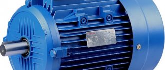
Asynchronous Motor Nameplate
It is necessary to distinguish between the rated mechanical power and the total electrical power of diverse electric motors
. The electric power that is supplied to the stator of the electric motor from the network is necessarily greater than the certain power on the shafts and greater than the active power that is consumed by the engine without return.
Regarding the mechanical characteristics of asynchronous electric drives:
- angular speeds;
- linear speeds;
- rotor rotation;
- nominal operating torques on the shafts.
How fast the rotational motion actually occurs can be estimated using the rotational speed. We are talking about the number of revolutions of the motor shafts per minute. Considering the fact that the drive is considered an asynchronous type, rotor torque can only appear if there is a difference between the speed of the rotors and the magnetic fields. This difference is called slip.
Connection
The stator windings of a three-phase ADKR can be connected in a “delta” or “star” circuit. In this case, the sprocket requires a higher voltage than the triangle.
Please note that an electric motor connected in different ways to the same network consumes different power. Therefore, you cannot connect an electric motor designed for a star circuit according to the delta principle. But in order to reduce starting currents, you can switch the star-delta contacts during the start-up, but then the starting torque will also decrease.
The connection diagrams are clear from Figure 4.
Rice. 4. Connection diagrams
To connect a three-phase electric motor to a single-phase current, phase-shifting elements are used: capacitors, resistors. For examples of such connections, see Figure 5. You can use either a star or a triangle.
Rice. 5. Examples of connection diagrams for a single-phase network
In order to control the operation of the motor, additional devices are connected to the stator electrical circuit.