Good time! You are trying to turn on your computer. The indicator on the system unit lights up. The fans began to rustle; You wait patiently and look at the monitor, but it remains dark and the indicator on it glows in standby mode.
If earlier during startup there was a short squeak from the speaker (which is located in the system unit), now there is silence... The system does not start. One common reason for this is a faulty computer power supply.
As always, “yesterday everything was fine, but today”... we will find out what power supplies there are and how you can replace them yourself at home. We will not repair them, we will quickly diagnose and replace them.
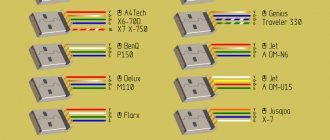
Color pinout of computer power supply connectors
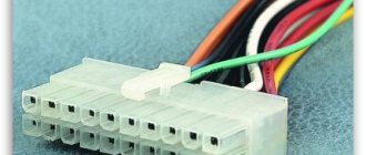
Modern computers use ATX power supplies, and a 20 or 24 pin connector is used to supply voltage to the motherboard. The 20-pin power connector was used during the transition from the AT standard to the ATX. With the advent of the PCI-Express bus on motherboards, 24-pin connectors began to be installed on power supplies.
The 20-pin connector differs from the 24-pin connector in the absence of contacts numbered 11, 12, 23 and 24. These contacts in the 24-pin connector are supplied with the duplicated voltage already present on the other contacts.
Pin 20 (white wire) previously served to supply −5 V in power supplies for ATX computers versions prior to 1.2. Currently, this voltage is not required for the operation of the motherboard, so in modern power supplies it is not generated and pin 20 is usually free.
Sometimes power supplies are equipped with a universal connector for connecting to the motherboard. The connector consists of two. One is twenty-pin, and the second is four-pin (with pin numbers 11, 12, 23 and 24), which can be attached to a twenty-pin connector and it will become 24-pin.
So if you are replacing a motherboard that requires a 24-pin connector instead of a 20-pin connector, you should pay attention; it’s quite possible that an old power supply will work if its set of connectors has a universal 20+4-pin connector.
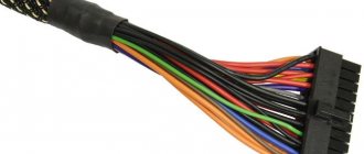
In modern ATX power supplies, there are also auxiliary 4, 6 and 8 pin connectors to supply +12 V voltage. They serve to supply additional supply voltage to the processor and video card.
As you can see in the photo, the +12 V supply conductor is yellow with a black stripe.
A Serial ATA connector is currently used to power hard drives and SSDs. Voltages and contact numbers are shown in the photo.
Outdated power supply connectors
This 4-pin connector was previously installed in the power supply to power a floppy drive designed for reading and writing from 3.5-inch floppy disks. Currently found only in older computer models.
Floppy disk drives are not installed in modern computers, as they are obsolete.
The four-pin connector in the photo is the one that has been in use for the longest time, but is already obsolete. It served to supply +5 and +12 V supply voltage to removable devices, hard drives, and disk drives. Currently, a Serial ATA connector is installed in the power supply instead.
The system units of the first personal computers were equipped with AT-type power supplies. One connector consisting of two halves was suitable for the motherboard. It had to be inserted in such a way that the black wires were next to each other. The supply voltage to these power supplies was supplied through a switch that was installed on the front panel of the system unit. However, according to the PG pin, it was possible to turn the Power Supply on and off using a signal from the motherboard.
Currently, AT power supplies are almost out of use, but they can be successfully used to power any other devices, for example, to power a laptop from the mains if its standard power supply fails, to power a 12 V soldering iron, or low-voltage light bulbs , LED strips and much more. The main thing is not to forget that the AT power supply, like any switching power supply, is not allowed to be connected to the network without an external load.
Computer power supply characteristics and choice of replacement
I’ll just tell you how to choose the right one in case of replacement. If you have a standard home computer, then it most likely has a “regular” full-size power supply. If the form factor of your computer case is something exotic, then you need to look for a compatible model from the corresponding line of cases, because the overall dimensions of the unit can be individual - depending on the model.
When we have visually determined the dimensions of the block, we move on to the next important characteristic - its power. It is always indicated on its body:
Therefore, we choose a power supply that is the same (or a little more powerful) if you plan to upgrade the hardware in the future. The more powerful the better. The next important point is the block connectors. Consider the used number and type of connectors that are on the “native” power supply:
And also the type and number of connectors feeding hard drives and DVD drives, because there may simply not be enough of them. You can use a used, but known-to-be-good unit from another computer that meets the specifications. And if you still don’t have enough connectors for connecting hard drives, we’ll buy the necessary adapters (molex/Sata):
I would especially like to mention power supplies for servers. Server blocks are always expensive and tailored to a specific server model. Sometimes there are two. They also change in pairs and are purchased to order.
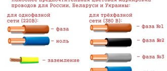
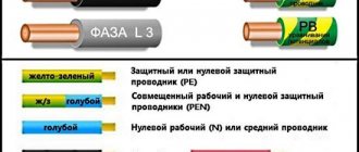
Reference table of color markings, voltage values and ripple range on power supply connectors
Wires of the same color coming out of the computer's power supply are soldered internally to one track of the printed circuit board, that is, connected in parallel. Therefore, the voltage on all wires of the same color is the same value.
| Table of color marking of wires, output voltages and ripple range of ATX power supply | |||||||
| Output voltage, V | +3,3 | +5,0 | +12,0 | -12,0 | +5.0 SB | +5.0 PG | GND |
| Wire color coding | orange | red | yellow | blue | violet | grey | black |
| Permissible deviation, % | ±5 | ±5 | ±5 | ±10 | ±5 | – | – |
| Permissible minimum voltage | +3,14 | +4,75 | +11,40 | -10,80 | +4,75 | +3,00 | – |
| Permissible maximum voltage | +3,46 | +5,25 | +12,60 | -13,20 | +5,25 | +6,00 | – |
| Ripple range no more than, mV | 50 | 50 | 120 | 120 | 120 | 120 | – |
Voltage +5 V SB (Stand-by) – (purple wire) is generated by an independent low-power power supply built into the power supply unit, based on one field-effect transistor and a transformer. This voltage ensures the computer operates in standby mode and serves only to start the power supply. When the computer is running, the presence or absence of +5 V SB voltage does not matter. Thanks to +5 V SB, the computer can be started by pressing the “Start” button on the system unit or remotely, for example, from an uninterruptible power supply unit in the event of a prolonged absence of 220 V supply voltage.
Voltage +5 V PG (Power Good) - appears on the gray wire of the power supply unit after 0.1-0.5 seconds if it is in good condition after self-testing and serves as an enabling signal for the operation of the motherboard.
When measuring voltages, the “negative” end of the probe is connected to the black wire (common), and the “positive” end is connected to the contacts in the connector. You can measure output voltages directly while the computer is running.
A voltage of minus 12 V (blue wire) is only needed to power the RS-232 interface, which is not installed in modern computers. Therefore, in power supplies of the latest models this voltage may not be present.
The deviation of the supply voltages from the nominal values should not exceed the values given in the table.
When measuring the voltage on the wires of the power supply, it must be connected to a load, for example, to a motherboard or a homemade load block.
Structural scheme
The figure shows an image of a block diagram typical for switching power supply system units.
ATX switching power supply device
Designations indicated:
- A – surge protector unit;
- B – low-frequency rectifier with a smoothing filter;
- C – auxiliary converter stage;
- D – rectifier;
- E – control unit;
- F – PWM controller;
- G – cascade of the main converter;
- H – high-frequency rectifier equipped with a smoothing filter;
- J – power supply cooling system (fan);
- L – output voltage control unit;
- K – overload protection.
- +5_SB – standby power mode;
- PG – information signal, sometimes designated as PWR_OK (needed to start the motherboard);
- PS_On – signal controlling the start of the power supply.
Installing an additional video card connector in the computer's power supply
Sometimes there are seemingly hopeless situations. For example, you bought a modern video card and decided to install it in your computer. There is the necessary slot on the motherboard for installing a video card, but there is no suitable connector on the wires for additional power supply to the video card coming from the power supply. You can buy an adapter, replace the entire power supply, or you can independently install an additional connector on the power supply to power the video card. This is a simple task, the main thing is to have a suitable connector, it can be taken from a faulty power supply.
First you need to prepare the wires coming from the connectors for the offset connection, as shown in the photo. An additional connector for powering the video card can be connected to the wires going, for example, from the power supply to drive A. You can also connect to any other wires of the desired color, but in such a way that there is enough length to connect the video card, and preferably nothing to them was no longer connected. The black wires (common) of the additional connector for powering the video card are connected to the black wire, and the yellow wires (+12 V), respectively, to the yellow wire.
The wires coming from the additional connector for powering the video card are tightly wrapped with at least three turns around the wire to which they are connected. If possible, it is better to solder the connections with a soldering iron. But even without soldering, in this case the contact will be quite reliable.
The work of installing an additional connector for powering the video card is completed by isolating the connection point, several turns, and you can connect the video card to the power supply. Due to the fact that the twisting points are located at a distance from each other, there is no need to isolate each twist separately. It is enough to cover only the area where the wires are exposed with insulation.
Refinement of the power supply connector for connecting the motherboard
When the motherboard fails or a computer is modernized (upgraded) and involves replacing the motherboard, I have repeatedly had to deal with the lack of a 24-pin power supply connector on the power supply.
The existing 20-pin connector fit well into the motherboard, but the computer could not work with this connection. A special adapter or replacement of the power supply was required, which was an expensive pleasure.
But you can save money if you do a little work yourself. The power supply, as a rule, has many unused connectors, among them there may be four, six or eight pins. The four-pin connector, as in the photo above, fits perfectly into the mating connector on the motherboard, which was left unoccupied when installing the 20-pin connector.
Please note that both in the connector coming from the computer's power supply and in the mating part on the motherboard, each contact has its own key, which prevents incorrect connection. Some contact insulators have a shape with right angles, while others have cut corners. You need to orient the connector so that it fits. If you can’t find the position, then cut off the interfering corner.
Separately, both the 20-pin and 4-pin connectors fit well, but they don’t fit together and interfere with each other. But if you grind down the contacting sides of both connectors a little with a file or sandpaper, they will fit in well.
After adjusting the connector housings, you can begin connecting the wires of the 4-pin connector to the wires of the 20-pin connector. The colors of the wires of the additional 4-pin connector are different from the standard one, so you do not need to pay attention to them and connect them as shown in the photo.
Be extremely careful, mistakes are unacceptable, the motherboard will burn out! Near left, pin No. 23, black in the photo, connects to the red wire (+5 V). Near right No. 24, yellow in the photo, is connected to the black wire (GND). The far left, pin No. 11, black in the photo, connects to the yellow wire (+12 V). The far right, pin No. 12, yellow in the photo, is connected to the orange wire (+3.3 V).
All that remains is to cover the connection points with a few turns of insulating tape and the new connector will be ready for use.
In order not to think about how to correctly install the assembly connector into the motherboard connector, you should apply a mark using a marker.
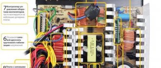
Presence of an active PFC block
Active PFC Block | GECID.com
I highly recommend paying attention to the presence of active PFC. PFC (Power Factor Correction), also known as a power factor correction circuit, is a special unit, usually represented by a large capacitor and a choke next to it. It stabilizes the output voltage and reduces drawdowns along the lines. PFC can be passive or active. The advantages of active over passive are better stability during voltage surges, less sensitivity to low mains voltage, a large input voltage range (from 110 to 230V), which ensures versatility, and a lower level of high-frequency interference on output lines. I advise you to choose units with active PFC, as they ensure more stable operation of all computer components.
How the computer's power supply is supplied with power from the mains
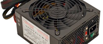
In order for constant voltages to appear on the colored wires of the power supply, supply voltage must be applied to its input. To do this, there is a three-pin connector on the wall where the cooler is usually installed. In the photo this connector is at the top right. It has three pins. The outer ones are supplied with supply voltage using a power cord, and the middle one is grounding, and when connected through the power cord, it is connected to the grounding contact of the electrical outlet. Below on some power supplies, for example this one, there is a power switch.
In old houses, the electrical wiring is made without a grounding loop; in this case, the grounding conductor of the computer remains unconnected. Experience in operating computers has shown that if the grounding conductor is not connected, this does not affect the operation of the computer as a whole.
The power cord for connecting the Power Supply to the mains is a three-core cable, at one end of which there is a three-pin connector for connecting directly to the Power Supply. At the second end of the cable there is a C6 plug with round pins with a diameter of 4.8 mm with a grounding contact in the form of metal strips on the sides of its body.
If you open the plastic sheath of the cable, you can see three colored wires. Yellow - green
– is grounding, and along brown and blue (may be of a different color), a supply voltage of 220V is supplied.
Yellow - green
the wire in the C6 plug is connected to the grounding side strips. So if you have to replace the plug, don't forget about it. You can learn everything about electrical plugs and the rules for connecting them from the website article “Electric Plug”.
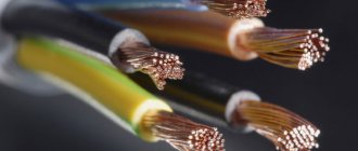
About the cross-section of wires coming out of the computer power supply
Although the currents that the power supply can supply to the load amount to tens of amperes, the cross-section of the output conductors, as a rule, is only 0.5 mm2, which allows current transmission through one conductor of up to 3 A. You can find out more about the load capacity of the wires from the article “On choosing a wire cross-section for electrical wiring.” However, all wires of the same color are soldered to one point on the printed circuit board, and if a block or module in a computer consumes more than 3 A of current, voltage is supplied through the connector along several wires connected in parallel. For example, voltage +3.3 V and +5 V is supplied to the motherboard via four wires. This ensures that up to 12 A of current is supplied to the motherboard.
80 PLUS Certification
Another important parameter to at least read: 80 PLUS certification. There are six of these certificates in total: 80 PLUS, 80 PLUS Bronze, 80 PLUS Silver, 80 PLUS Gold, 80 PLUS Platinum, 80 PLUS Titanium. Often, PC builders mistakenly believe that this certificate is an indicator of reliability and quality. I hasten to assure you that this is not so. Such a certificate only shows the efficiency (coefficient of performance) of the unit, or more precisely, how many watts of power are supplied to power the components, and how many are converted into heat (losses). Accordingly, the higher the efficiency, the higher the certificate. Just in case, I note that in power supplies the efficiency is calculated according to the principle (Number of declared Watts) / (Number of Watts consumed by the power supply from the network). In other words, the power supply will deliver the declared power regardless of the efficiency.
You should pay attention to this point only if energy efficiency is extremely important to you (for example, the computer is being assembled for mining or server use). You should not chase a platinum or titanium certificate if the machine is being built for gaming or work. Sometimes overpaying for a block with a high certificate does not pay for itself even after several years.
Efficiency in test category: 115 V
| Load | 10% | 20% | 50% | 100% |
| 80 PLUS | — | 80% | 80% | 80% |
| 80 PLUS Bronze | — | 82% | 85% | 82% |
| 80 PLUS Silver | — | 85% | 88% | 85% |
| 80PLUS Gold | — | 87% | 90% | 87% |
| 80PLUS Platinum | — | 90% | 92% | 89% |
| 80 PLUS Titanium | 90% | 92% | 94% | 90% |
Efficiency in test category: 230 V
| Load | 10% | 20% | 50% | 100% |
| 80 PLUS | — | 80% | 80% | 80% |
| 80 PLUS Bronze | — | 81% | 85% | 81% |
| 80 PLUS Silver | — | 85% | 89% | 85% |
| 80PLUS Gold | — | 88% | 92% | 88% |
| 80PLUS Platinum | — | 90% | 94% | 91% |
| 80 PLUS Titanium | 90% | 94% | 96% | 91% |