7.1. OPERATING PRINCIPLE AND DESIGN
Two fixed poles N and S create magnetic flux. A steel core in the form of a cylinder is placed in the space between the poles (Fig. 7.1.1).
A coil of copper wire abcd is placed on the outer surface of the cylinder, insulated from the core. Its ends are connected to two rings, on which brushes 1 and 2 are placed. A load zn is connected to the brushes. If you rotate the core with a frequency n in the direction indicated in the figure, then the turn abcd, rotating, will intersect the magnetic lines of force, and an emf will be induced at its ends. And if a load zn is connected to the coil, then current will flow. The direction of the current is determined by the “right hand” rule. From the figure it can be seen that the direction of the current will be from points b to a and from d to c. Accordingly, in the external circuit, the current flows from brush 1 to brush 2. We denote brush 1, from which the current is diverted to the external circuit, (+), and brush 2, through which the current returns to the machine, we denote (-). When the coil is rotated 180°, the conductors ab and cd change places, the sign of the potential on brushes 1 and 2 changes, and the current in the external circuit changes in the opposite direction. Thus, an alternating sinusoidal current flows in the external circuit (Fig. 7.1.2).
To rectify alternating current, it is necessary to use a collector in the machine (Fig. 7.1.3).
In the simplest case, these are two half rings and the ends of the turns abcd are soldered to them. Half rings insulate from each other and from the shaft. When rotating in coil abcd, an alternating EMF still arises in it, but under each brush there will be an EMF of only one sign: the upper brush will always have (+), and the lower brush will always have (-). The current curve in the external circuit will have a different shape (Fig. 7.1.4).
The graph shows that the lower half-wave is replaced by the upper one. If you use not one turn, but two and connect their ends to the collector plates, of which there are now 4, then the rectified current curve will be different. If there are several turns, the rectified voltage curve will be smoother (Fig. 7.1.5).
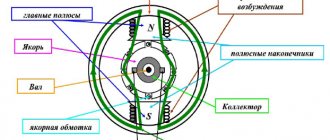
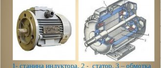
A DC machine is structurally composed of a stationary part - the stator and a rotating part - the rotor. The stator has a frame, on the inner surface of which magnetic poles with windings are attached (Fig. 7.1.6).
The rotor of a machine is often called an armature. It consists of a shaft, a cylindrical core, a winding and a collector (Fig. 7.1.7).
The magnetic poles and the armature core are made from separate sheets of electrical steel. The sheets are coated with insulated paper or varnish to reduce hysteresis and eddy current losses. The collector is made of copper plates having a complex shape (Fig. 7.1.8). The plates are insulated from each other with a special heat-resistant gasket. The same insulation is found between the commutator and the motor shaft. A set of collector plates forms a cylinder-collector.
Adjacent to the outer surface of the commutator are current-collecting brushes, which are made of compressed copper and carbon powder. The brush is placed in a metal cage and pressed against the commutator by springs (Fig. 7.1.9).
7.2. METHODS OF EXCITING DC MACHINES
Excitation is a concept related to the creation of the main magnetic field of a machine. In machines with electromagnetic excitation, the main field is created by the field windings. There are designs in which the excitation is created by permanent magnets placed on the stator. There are four circuits for connecting stator windings: with independent, parallel, series and mixed excitation (Fig. 7.2.1).
Images under points b, c, d in Fig. 7.2.1 are called self-excited circuits. The process of self-excitation occurs due to the residual magnetization of the poles and frame. When the armature rotates in this small magnetic field (FOST = 0.02 0.03 FO), an EMF is induced - EOST. Since the field winding is connected through brushes to the armature, current will flow in it. This current will strengthen the magnetic field of the poles and lead to an increase in the armature EMF. A large EMF will again increase the excitation current and the magnetic flux will increase until the machine is completely magnetized.
Behavior of an electric motor when loads change
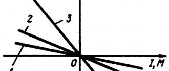
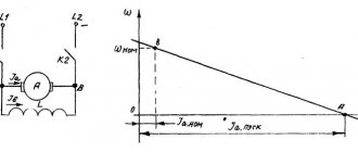
The mechanical characteristic shows the stability of the electric motor over a wide range of load changes, describing the dependence of the torque created by the electric motor on the operating speed of the shaft.
The traction characteristics of the mechanism of this type make it possible to maintain the magnitude of the torque with significant changes in the number of shaft revolutions. Typically, the traction parameters of the unit should ensure a decrease in this parameter by no more than 5%. A simple study demonstrates that the inhibitory parameters turn out to be similar due to the reversibility of the processes. These provisions also apply to the case of mixed excitation.
In other words, such an electric motor is characterized by a rigid characteristic. This nature of work is considered an important advantage of the unit of this type.
7.3. ARCH WINDINGS OF DC MACHINE
To operate a DC machine, you need two windings; field windings and armature windings. The first, as is known, serves to create the main magnetic flux in the machine, and in the second, energy is converted. The armature winding is a closed system of conductors laid in grooves. An element of the armature winding is a section, which can be one or many turns. The section consists of active sides and frontal parts. When the armature rotates, an emf is induced in each of the active sides, the value of which is equal to:
those. it depends on the magnetic induction of the poles of the HRV, the length of the conductor L and the speed of its movement V. In a real machine, be it a generator or a motor, all conductors of the armature winding participate in inducing the EMF. The value of the total EMF:
where n is the speed of rotation of the armature (rotor), rpm; F is the magnetic flux of the poles; Ce is a constant coefficient depending on the number of turns in the section. The armature winding can be loop or wave. The loop winding, if depicted in expanded form, has the following form (Fig. 7.3.1):
The distance between the active sides of one section is called the first winding pitch - y1. The distance between the beginning of the second section and the end of the first is called the second winding pitch - y2. The distance between the beginnings of sections following each other is called the resulting step - y. The winding pitches are determined by the number of slots. The distance between the collector plates, where the beginning and end belonging to the same section are soldered, is called the step along the collector - uk. In a loop winding uk = 1. The step uk is determined by the number of collector plates. The unfolded wave winding looks like: (Fig. 7.3.2).
The shape of the wave winding is different from the loop winding and, therefore, there will be a different connection of sections. However, the steps of the wave winding have a common definition with the loop winding. The step along the collector here is significantly greater than unity (uk >> 1).
The concept of arousal and its features
Excitation is a term used by electrical engineers that means the creation of a magnetic field. The simple magnet used in this chapter to illustrate the operation of a generator is of course capable of creating a current in the windings of the generator, but a permanent magnet ceases to be permanent under the influence of vibration and heat.
Process description
Typically, the rotor is made in the form of an electromagnet made of mild steel or iron, on which a coil is wound. A direct current is passed through the coil, inducing a magnetic field in the iron rotor. The strength of the magnetic field induced by such a cut depends on the strength of the current passed through the excitation winding, and this fact provides another advantage, since it allows you to regulate the emf in the stator windings of the generator.
7.4. EMF AND ELECTROMAGNETIC TORQUE OF DC GENERATOR
As already noted, the EMF induced in the winding of the rotating armature of the generator is proportional to the magnetic flux of the poles and the frequency of its rotation:
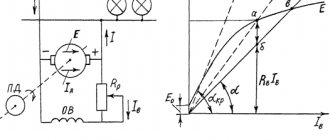
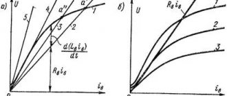
The magnetic flux in the generator, as is known, is created by the excitation current Iв. If you rotate the armature with a constant frequency n and continuously measure the output emf E, then you can plot a graph E = f (Iв) (Fig. 7.4.1).
This dependence is called the idle speed characteristic.
It is built for a mode when the generator has no external load, i.e. running idle. If you connect a load to the generator, the voltage at its terminals will be less than E by the value of the voltage drop in the armature circuit:
Here: U is the voltage at the terminals; E - EMF in idle mode; IА - armature current; RI is the resistance in the armature circuit. The voltage drop in the armature circuit usually does not exceed 2-8% of the generator's emf. The decrease in voltage at the generator output is associated with demagnetization of the machine by the magnetic field of the armature, as well as a drop in voltage in its windings. In every direct current machine, there is an interaction between the armature current IА and the magnetic flux F. As a result, an electromagnetic force acts on each conductor of the armature winding:
where B is magnetic induction, IА is the current in the armature winding, L is the length of the armature. The direction of this force is determined by the left-hand rule. Let us substitute here the average value of the magnetic induction of the HRV and the magnitude of the current in each conductor of the armature winding I = IА / 2 a. We get
Electromagnetic torque acting on the machine armature, with the number of winding conductors N:
where is a constant value for a given machine; d—anchor diameter; p—number of pole pairs; N is the number of conductors of the armature winding; a is the number of pairs of parallel branches. When the machine operates in generator mode, the electromagnetic torque acts against the rotation of the armature, i.e. is inhibitory. To drive a generator, an electric motor requires power, which must cover all losses in the generator:
where P is the useful electrical power of the generator; DРЯ - losses in the armature winding; DРВ - losses in the excitation winding; DРМ - losses due to magnetization of the machine; DРМЭХ - mechanical losses associated with friction of rotating parts.
The efficiency of the generator is determined by the ratio:
Modern DC generators have an efficiency of 90-92%.
7.5. DC MOTOR
According to the principle of reversibility, a DC machine can operate both as a generator and as a motor. The EMF equation for the motor is based on Kirchhoff’s 2nd law, taking into account the direction of the EMF:
where
Armature circuit current:
In accordance with the formula Ea = Ce Ф n, the rotation speed is determined by the expression:
Substituting the value of E from the equation U = E - IЯ RЯ, we get:
those. The engine speed is directly proportional to the applied voltage and inversely proportional to the excitation magnetic flux. From this formula it can be seen that there are possible ways to regulate the rotation speed of a DC motor: 1. By changing the network voltage U. By adjusting the supplied voltage U, you can change the rotation speed. 2. By including additional resistance in the armature circuit (R'Я = RЯ + RADOB). By changing the resistance RDOB, the rotation speed is changed. 3. By changing the magnetic flux F. Machines with permanent magnets are not regulated. Machines with electromagnets make it possible to regulate the flow Ф by changing the excitation current IB. In Fig. 7.5.1. shows a diagram of connecting a DC motor to the network.
According to the law of electromagnetic induction, when current passes through the armature winding, its conductors interact with the magnetic field of the poles. Each conductor of the winding will be subject to an electromagnetic force Rem = BCPLI, proportional to the magnetic induction of the poles B, the length of the conductor L and the current I flowing through the conductor. The direction of this force is determined by the right hand rule. Without repeating the reasoning carried out for the DC generator, we write down the expression for the torque:
M=CMФ IЯ
where CM is the proportionality coefficient. The torque of motors with independent and parallel excitation can either increase or decrease with increasing load, since with increasing current consumption I and pole demagnetization, magnetic flux F decreases.
Series-wound motors have different characteristics from the above motors. From the diagram shown in Fig. 7.2.1c, it is clear that the magnetic flux in the machine is created by an excitation winding connected in series with the armature winding. Therefore, IB = IА and the expression for the torque will be:
The last formula shows that the greater the load on the engine, the greater the torque will be. This circumstance makes a motor with sequential excitation indispensable in electric transport (trams, trolleybuses, etc.). Reversing or changing the direction of rotation of DC motors can be accomplished by changing the polarity of the current either in the armature winding or in the field winding.
Switching and monitoring of engines
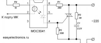
This type of engine has two modes: they can be on or off. This switching is done by switches, relays, transistors or MOSFETs.
The control circuit uses a bipolar transistor; it plays a key role in switching modes.
Motor speed control
Because the speed of this type of motor is proportional to the voltage at the terminals, a transistor can be used to regulate the voltage across them. These two transistors are connected as a pair to control the main rotor current.
It will be interesting➡ Single-phase asynchronous motors in the service of humanity
Pulse speed adjustment
The rotation speed of this type of electric motor is proportional to the average pressure at the second terminal.
Changing the Direction of a DC Motor
There are many advantages to controlling the speed of this type of electric motor, but there is one big disadvantage: the direction of rotation is always the same. In many cases, the machine operates on a simple principle to move forward and backward. H-bridge motor circuit.
The basic configuration of four switches, either electromechanical relays or transistors, is similar to the letter H with the motor located on the bus in the middle.
7.6. ELECTRICAL MACHINE AMPLIFIERS
The simplest power amplifier is a conventional DC generator with independent excitation. The gain of the machine is determined by the ratio of the current flowing in the armature winding to the excitation current:
In this design, the gain is about 15 - 30. The amplification capacity of the generator can be increased if you use a cascade circuit for connecting generators. In this case, the excitation winding of the second is connected from the output of the first generator, and the output from the second generator will exceed the power of the input of the first by 1000 or more times. The cascade scheme is rarely used due to its bulkiness and high cost. More often they use so-called electric machine amplifiers (EMA). The electrical circuit of the EMU is shown in Fig. 7.6.1.
Structurally, the electric machine amplifier is a DC commutator machine with independent excitation, having two sets of brushes (longitudinal 1-1′ and transverse 2-2′). The current flowing through the excitation winding Ib creates a longitudinal magnetic flux Фd, directed along the axis of the poles of the machine. When the armature rotates, an emf E2 = C n Фd appears on the transverse brushes 2-2′. Since they are short-circuited, a large current I2 appears in the armature winding. This current creates in the armature winding a strong transverse magnetic field of the armature reaction Фq, stationary in space and directed along the axis of the brushes 2-2′. Under the influence of magnetic flux Фq in the armature winding between brushes 1-1′, an emf E1 = C n Фq >>E2 arises, since Фq >>Фd. When a load Rн is connected to brushes 1-1′, a current Iа will flow in the circuit, tens of thousands of times greater than the current Iв. Electric machine amplifiers are used to automatically control powerful electric motors.
Construction of the engine and its scope
The diagram of the electric motor of the type in question is shown below.
It follows from it:
- the total current consumed by the electric motor from the source is I = I I + I V, where I I, I V are the currents through the armature and field winding, respectively;
- at the same time I B does not depend on I I, that is, it does not depend on the load.
The operating principle of an electric motor determines its traction properties. The device is used when starting does not require high torque, that is, when the operating modes of the drive mechanisms do not involve the creation of large starting loads. This is typical for machine tools and fans.
For practice, such useful traction parameters of such electric mechanisms as
- stability of operation under load fluctuations;
- high efficiency due to the fact that I does not flow through the OB.
Starting in case of insufficient torque is ensured by switching to a mixed type circuit.
7.7. SINGLE-ARM CONVERTERS
To convert alternating current into direct current, as is known, rectifiers are used. Conversion of direct current into alternating current can be carried out using electrical machine converters. A cascade of two machines: (an asynchronous AC motor and a DC generator) completely solves this problem. But there is a situation when it is necessary to convert low-voltage direct current into high-voltage direct current. This is done in one combined machine, consisting of a motor and a DC generator with a common magnetic system. On the low voltage side it is an electric motor, and on the high voltage side it is a direct current generator with independent excitation. The same slots in the converter armature contain independent low and high voltage windings. The ends of the windings are connected to the corresponding collector (Fig. 7.7.1), and the high-voltage winding has a significantly larger number of conductors than the low-voltage winding. Single-armature converters are widely used in aviation technology, as well as in general industrial installations, where the primary source of direct current is a battery. Single-armature DC-to-three-phase AC converters differ from those considered in that the high-voltage winding consists of
three sections offset from each other by 120°. The terminals of the sectional windings are soldered to three slip rings and, using current-collecting brushes, alternating current is transmitted to the consumer.
Powering the rotor with direct current: process features
In order for the magnetic field in the rotor not to change direction, its coil must be powered by a direct current of the same polarity. Current is supplied to the rotating coil through carbon brushes and commutator rings.
To power the rotor winding with direct current, two methods are used: self-excitation and excitation from an external source (usually from a battery).
Rice. 3.14. Toothed generator rotor.
Generator Excitation: Understanding the Definition
Excitation of the generator is a process that occurs on the basis of magnetomotive force. It carries out the process of inducing a magnetic field, which, in turn, produces the process of generating electricity. To excite the first generation generators, special DC rotators were used, which are also called exciters. Their winding received DC power from another generator, which is usually called a sub-exciter. All components are placed on one shaft, and their rotation occurs synchronously.
Generator field winding: familiarization with the definition
The generator excitation winding is one of the main structural elements of a synchronous generator. It receives power from a source providing direct current. Most often, the source function is performed by an electronic voltage generator. Such regulators are used in new models operating on the basis of a self-exciter. And self-excitation, in turn, is based on the fact that the initial excitation occurs with the help of the residual magnetism of the magnetic circuit of a synchronous generator (SG). It is important to understand that alternating current energy comes precisely from the SG stator winding, transforming it into direct current energy.
What is the generator excitation winding used for?
The rotor winding is excited by a direct current source. The rotor rotates with the help of the prime mover, thereby the magnetic field created in the rotor also rotates with it at the same speed. Now the magnetic field lines cross the stator winding located around the rotor. As a result, an alternating electromotive force (emf) is formed in the winding.
Generator excitation coil: introduction to the definition
The generator field coil is a special electromagnet that is used to generate an electromagnetic field in electromagnetic machines. It consists of a coil and a wire through which current flows. If we take rotating machines as an example, then the excitation coils are wound on a special iron magnetic core. It is the latter that performs the function of directing the magnetic field line. The magnetic circuit includes two main components:
- The stator is stationary.
- Rotor - rotates around the stator.
The magnetic field lines continuously pass from the stator to the rotor and back. The field coils can be located either on the stator or on the rotor.
7.8. DC TACHOGENERATORS
Tachogenerators are low-power electrical machines that operate in generator mode and serve to convert its rotation frequency into an electrical signal. Direct current tachogenerators are electric commutator machines based on their operating principle and design. The output characteristic of the tachogenerator is the dependence of the voltage at the armature terminals Uya on its rotation frequency n at a constant magnetic excitation flux Ф and a constant load resistance Rload. In Fig. 7.8.1 shows the output characteristic of the tachogenerator at different Rload.
7.9. MICROMOTORS USED IN CHILDREN'S TECHNICAL CREATIVITY
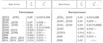
The variety of children's technical products does not allow us to settle on specific solutions. The structural composition of any moving object almost always includes an electric motor. It is he who converts electrical energy into mechanical movement. The type of electric drive of the model primarily depends on the power source. If the model operates autonomously, then, naturally, it also requires an autonomous power source. This is usually an electrochemical battery or accumulator. When choosing an electric drive circuit, you only need to match the voltage of the electric motor with the power source. In stationary installations, a conventional electrical network with a voltage of 220, 127 V is used. To reduce the voltage to a safe level, step-down transformers and sometimes AC-to-DC rectifiers are used. Such devices may not be included in the design of the product and are auxiliary. Below in the table. 7.9.1 provides the technical characteristics of the electric motors most used in technical creativity.
Features of operation
The engine is equipped with overload protection mechanisms. Protection must be done with a time delay. The protection must operate in isolation, or as a signal, or as a ventilation system, if such an option is possible.
H-bridge diagram
Detailed motor H-bridge truth table