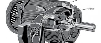
Rotor:
The moving part of an electric motor that rotates with the electric motor shaft, moving along with the magnetic field of the stator.
Stator:
Fixed component of an electric motor. It includes several windings whose polarity changes when alternating current (AC) passes through them. Thus, a combined stator magnetic field is created.
Rotation under the influence of a magnetic field
The advantage of magnetic fields created by current-carrying coils is the ability to swap the poles of a magnet by changing the direction of the current. It is this ability to change poles that is used to convert electrical energy into mechanical energy.
Like poles of magnets repel each other, opposite poles attract. This property can be said to be used to create continuous rotor motion by constantly changing the polarity of the stator. The rotor here is a magnet that can rotate.
Pole rotation using alternating current
Pole rotation using alternating current
The polarity is constantly reversed using alternating current (AC). Next we will see how the rotor is replaced by a magnet, which rotates under the influence of induction. Alternating current plays an important role here, so it will be useful to provide some brief information about it here:
Alternating current - AC
Alternating current is understood as an electric current that periodically changes its direction in a circuit so that the average value of the current over the period is zero. A rotating magnetic field can be created using three-phase power. This means that the stator is connected to a three-phase AC source. A complete cycle is defined as a 360 degree cycle. This means that each phase is located at an angle of 120 degrees relative to the other. The phases are depicted as sinusoidal curves, as shown in the figure.
Three-phase alternating current
Three-phase power is a continuous series of overlapping alternating current (AC) voltages.
Pole reversal
The following pages explain how the rotor and stator interact to make the motor rotate.
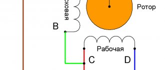
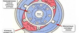
For clarity, we replaced the rotor with a rotating magnet and the stator with coils. On the right side of the page is an image of a two-pole three-phase electric motor. The phases are connected in pairs: the 1st phase corresponds to coils A1 and A2, the 2nd phase - B1 and B2, and the 3rd phase corresponds to C1 and C2. When current is applied to the stator coils, one of them becomes the north pole, the other becomes the south pole. Thus, if A1 is the north pole, then A2 is the south pole.
AC Power
The windings of phases A, B and C are located at an angle of 120 degrees relative to each other.
The number of poles of the electric motor is determined by the number of intersections of the winding field with the rotor field. In this case, each winding is crossed twice, which means that we have a two-pole stator. Thus, if each winding appeared four times, it would be a four-pole stator, etc.
When electric current is applied to the phase windings, the motor shaft begins to rotate at a speed determined by the number of poles (the fewer poles, the lower the speed)
Rotor rotation
The following describes the physical principle of operation of an electric motor (how the rotor rotates inside the stator). For clarity, let's replace the rotor with a magnet. All changes in the magnetic field occur very quickly, so we need to break the whole process into stages. When three-phase alternating current passes through the stator windings, a magnetic field is created in it, resulting in mechanical forces that cause the rotor to rotate in the direction of rotation of the magnetic field.
Once it starts rotating, the magnet will follow the changing magnetic field of the stator. The stator field is changed so as to maintain rotation in one direction.
Synchronous and asynchronous electric machines
There are three types of AC motors: synchronous, the angular speed of the rotor coincides with the angular frequency of the stator magnetic field; asynchronous - in them the rotation of the rotor lags behind the rotation of the field; commutator motors, the design and operating principle of which are similar to DC motors.
Synchronous speed
The rotation speed of an AC electric machine depends on the angular frequency of the stator magnetic field. This speed is called synchronous. In synchronous motors, the shaft rotates at the same speed, which is an advantage of these electric machines.
To do this, the rotor of high-power machines has a winding to which a constant voltage is applied, creating a magnetic field. In low power devices, permanent magnets are inserted into the rotor, or there are pronounced poles.
Slip
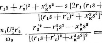
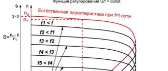
In asynchronous machines, the number of shaft revolutions is less than the synchronous angular frequency. This difference is called the "S" slip. Due to sliding, an electric current is induced in the rotor and the shaft rotates. The larger S, the higher the torque and the lower the speed. However, if the slip exceeds a certain value, the electric motor stops, begins to overheat and may fail. The rotation speed of such devices is calculated using the formula in the figure below, where:
- n – number of revolutions per minute,
- f – network frequency,
- p – number of pole pairs,
- s – slip.
Formula for calculating the speed of an asynchronous motor
There are two types of such devices:
- With squirrel-cage rotor. The winding in it is cast from aluminum during the manufacturing process;
- With wound rotor. The windings are made of wire and are connected to additional resistances.
Speed adjustment
During operation, it becomes necessary to adjust the speed of electrical machines. This is done in three ways:
- Increasing additional resistance in the rotor circuit of electric motors with a wound rotor. If it is necessary to greatly reduce the speed, it is possible to connect not three, but two resistances;
- Connecting additional resistances in the stator circuit. It is used to start high-power electrical machines and to regulate the speed of small electric motors. For example, the speed of a table fan can be reduced by connecting an incandescent lamp or capacitor in series with it. The same result is achieved by reducing the supply voltage;
- Changing the network frequency. Suitable for synchronous and asynchronous motors.
Attention! The rotation speed of commutator electric motors operating from an alternating current network does not depend on the frequency of the network.
Induction
Previously, we established how an ordinary magnet rotates in a stator. AC motors have rotors rather than magnets. Our model is very similar to a real rotor, except that the rotor is polarized under the influence of a magnetic field. This is caused by magnetic induction, due to which an electric current is induced in the rotor conductors.
Induction
Basically the rotor works the same way as a magnet. When the electric motor is turned on, current flows through the stator winding and creates an electromagnetic field that rotates in a direction perpendicular to the rotor windings. Thus, a current is induced in the rotor windings, which then creates an electromagnetic field around the rotor and rotor polarization.
In the previous section, to make it easier to explain the principle of operation of the rotor, replacing it with a magnet for clarity. Now let's replace the stator with a magnet. Induction is a phenomenon that occurs when a conductor moves in a magnetic field. The relative movement of a conductor in a magnetic field leads to the appearance of a so-called induced electric current in the conductor. This induced current creates a magnetic field around each rotor conductor winding. Since three-phase AC power causes the stator's magnetic field to rotate, the induced magnetic field of the rotor will follow this rotation. This way the motor shaft will rotate. AC motors are often called AC induction motors, or AC induction motors.
Rotation speed and sliding.
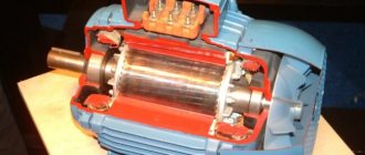
An asynchronous three-phase motor, like all electric motors, consists of two main parts: a stationary stator and a rotor rotating inside it. Both the stator and the rotor have windings made of turns of copper or aluminum conductor laid in slots. The rotor winding can be either a phase winding, in which the ends of each phase are led out to slip rings mounted on the rotor shaft, or short-circuited and without leads. The mechanical characteristics of squirrel-cage induction motors largely depend on the shape and size of the rotor slots, as well as on the method of making the rotor winding. These characteristics distinguish between motors with a normal, deep groove, and also with a double rotor winding (the so-called “double squirrel cage”). The operating principle of an asynchronous three-phase motor is based on the fact that alternating current, passing through the three-phase stator winding, creates a magnetic field around it, rotating at the frequency of the alternating current supply network. The field lines cross the turns of the rotor winding (either short-circuited or through a resistance) and induce an electromotive force (EMF) in it, causing a current in the rotor winding. The rotor current, in turn, creates a magnetic field that interacts with the rotating stator field and causes the motor rotor to rotate in the direction corresponding to the direction of rotation of the stator field. The rotation speed of the stator magnetic flux depends on the network frequency and the number of poles of the stator winding and is determined by the formula: nc=60fc/p [rpm], (1-1) where fc is the network frequency; p – number of pole pairs of the stator winding. The rotor rotation speed is less than the stator field rotation speed, found by formula (1-1), by the amount of slip. This condition is necessary for the operation of an asynchronous motor, since if the rotor rotated at the same angular speed as the rotating stator field, i.e. synchronously, then the turns of the rotor winding would not intersect the stator field lines of force and would not be induced in the rotor current, and, consequently, the reason causing its rotation would disappear. Slip is expressed in relative units or as a percentage and is determined by the formulas S=(nc-nn)/nc (1-2) or S=100%(nc-nn)/nc; (1-2) here nc is the synchronous rotation speed of the stator field, rpm; nн – rated rotor rotation speed, rpm. The material is taken from the “Handbook of Asynchronous Motors and Control Equipment” by G. A. Karvovsky and S. P. Oskorkov. Gosenergoizdat, 1962
Operating principle of electric motors
Induction motors consist of a rotor and a stator.
The currents in the stator windings are created by the phase voltage, which drives the induction motor. These currents create a rotating magnetic field, also called a stator field. The rotating magnetic field of the stator is determined by the currents in the windings and the number of phase windings.
A rotating magnetic field forms a magnetic flux. The rotating magnetic field is proportional to the electric voltage, and the magnetic flux is proportional to the electric current.
The rotating magnetic field of the stator moves faster than the rotor, which promotes the induction of currents in the windings of the rotor conductors, resulting in the formation of a rotor magnetic field. The magnetic fields of the stator and rotor form their own fluxes, these fluxes will attract each other and create a torque that causes the rotor to rotate. The operating principles of an induction motor are shown in the illustrations on the right.
Thus, the rotor and stator are the most important components of an AC induction motor. They are designed using CAD (Computer Aided Design). Next we will talk in more detail about the design of the rotor and stator.
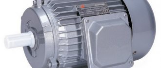
Motor stator
The stator is the stationary electrical component of an electric motor. It includes several windings, the polarity of which constantly changes as alternating current (AC) passes through them. Thus, a combined stator magnetic field is created.
All stators are installed in a frame or housing. The stator housing of Grundfos electric motors for electric motors up to 22 kW is most often made of aluminum, and for electric motors with higher power - from cast iron. The stator itself is installed in the stator housing. It consists of thin plates of electrical steel wrapped in insulated wire. The core consists of hundreds of such plates. When power is applied, alternating current passes through the windings, creating an electromagnetic field perpendicular to the rotor conductors. Alternating current (AC) causes the magnetic field to rotate.
The stator insulation must comply with the requirements of IEC 62114, which provides different protection classes (temperature levels) and temperature change (AT). Grundfos electric motors have protection class F, and when the temperature increases, class B. Grundfos produces 2-pole motors with power up to 11 kW and 4-pole motors with power up to 5.5 kW. Grundfos purchases more powerful electric motors from other companies whose product quality meets Grundfos standards. For pumps, stators with two, four and six poles are mainly used, since the speed of the electric motor shaft determines the pressure and flow of the pump. The stator can be manufactured to handle different voltages, frequencies and output powers, as well as a variable number of poles.
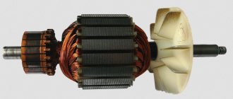
Motor rotor
Electric motors use so-called “squirrel wheels” (squirrel-cage rotors), the design of which resembles squirrel drums.
When the stator rotates, the magnetic field moves perpendicular to the windings of the rotor conductors; current appears. This current circulates through the windings of the conductors and creates magnetic fields around each rotor conductor. Since the magnetic field in the stator is constantly changing, the field in the rotor also changes. This interaction causes the rotor to move. Like the stator, the rotor is made of electrical steel plates. But, unlike the stator, with windings made of copper wire, the rotor windings are made of cast aluminum or silumin, which act as conductors.
Asynchronous electric motors
In previous sections, we discussed why AC motors are also called induction motors, or squirrel wheel motors. Next, we will explain why they are also called asynchronous electric motors. In this case, the relationship between the number of poles and the number of revolutions made by the rotor of the electric motor is taken into account.
The rotation frequency of the magnetic field is generally considered to be the synchronous rotation frequency (Ns). The synchronous speed can be calculated as follows: line frequency (F) multiplied by 120 and divided by the number of poles (P).
If, for example, the mains frequency is 50 Hz, then the synchronous speed for a 2-pole electric motor is 3000 rpm.
The synchronous speed decreases as the number of poles increases.
The table below shows the synchronous speed for different numbers of poles. Synchronous speed for different number of poles
| Number of poles | Synchronous speed 50 Hz | Synchronous speed 60 Hz |
| 2 | 3000 | 3600 |
| 4 | 1500 | 1800 |
| 6 | 1000 | 1200 |
| 8 | 750 | 900 |
| 12 | 500 | 600 |
Slip of an asynchronous motor. Rotor speed
A distinctive feature of an asynchronous motor is that the rotor speed n2 is less than the synchronous speed of the stator magnetic field n1.
This is explained by the fact that the EMF in the rotor winding rods is induced only when the rotation frequencies n21 are unequal . The rotation frequency of the stator field relative to the rotor is determined by the sliding frequency ns=n1-n2. The lag of the rotor from the rotating field of the stator is characterized by a relative value s called slip:
,
· where s is the slip of an asynchronous electric motor,
· n1 – rotation frequency of the stator magnetic field, rpm,
· n2 – rotor speed, rpm,
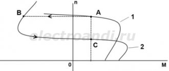
Let us consider the case when the rotor rotation frequency coincides with the rotation frequency of the stator magnetic field. In this case, the relative magnetic field of the rotor will be constant, thus no EMF, and therefore no current, will be created in the rotor rods. This means that the force acting on the rotor will be zero. This will slow down the rotor. After which an alternating magnetic field will again act on the rotor rods, thus the induced current and force will increase. In reality, the rotor of an asynchronous electric motor will never reach the rotation speed of the stator magnetic field. The rotor will rotate at a certain speed which is slightly less than the synchronous speed.
The slip of an asynchronous motor can vary in the range from 0 to 1, i.e. 0-100%. If s~0, then this corresponds to the idle mode, when the engine rotor experiences practically no counteracting torque; if s=1 - short circuit mode, in which the motor rotor is stationary (n2 = 0). Slip depends on the mechanical load on the motor shaft and increases with its growth.
The slip corresponding to the rated load of the motor is called rated slip. For low and medium power asynchronous motors, the rated slip varies from 8% to 2%.
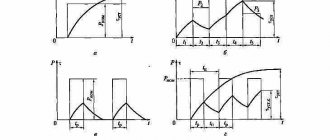
Energy conversion
An asynchronous motor converts electrical energy supplied to the stator windings into mechanical energy (rotation of the rotor shaft). But the input and output power are not equal to each other since energy losses occur during conversion: friction, heating, eddy currents and hysteresis losses. This energy is dissipated as heat. Therefore, an asynchronous electric motor has a fan for cooling.
Motor slip
Now we already know that AC electric motors are called asynchronous because the moving field of the rotor lags behind the field of the stator.
In AC motors, torque results from the interaction between the rotor and the rotating magnetic field of the stator. The magnetic field of the rotor windings will tend to approach the magnetic field of the stator, as described earlier. During operation, the rotor speed is always lower than the speed of the stator magnetic field. Thus, the rotor magnetic field can cross the stator magnetic field and create torque. This difference in the rotational speed of the rotor and stator fields is called slip and is measured in %. Sliding is necessary to create torque. The greater the load, and therefore the torque, the greater the slip.
DC motors
Resonance frequency: formula
In addition to AC machines, there are electric motors connected to a DC network. The speed of such devices is calculated using completely different formulas.
Rated rotation speed
The speed of a DC machine is calculated using the formula in the figure below, where:
- n – number of revolutions per minute,
- U – network voltage,
- Rya and Iya – armature resistance and current,
- Ce – motor constant (depending on the type of electric machine),
- Ф – stator magnetic field.
These data correspond to the nominal values of the parameters of the electric machine, the voltage on the field winding and the armature or the torque on the motor shaft. Changing them allows you to adjust the rotation speed. It is very difficult to determine the magnetic flux in a real motor, so calculations are made using the current flowing through the field winding or armature voltage.
Formula for calculating the speed of a DC motor
The speed of commutator AC motors can be found using the same formula.
Speed adjustment
Adjustment of the speed of an electric motor operating from a DC network is possible within a wide range. It is possible in two ranges:
- Up from nominal. To do this, the magnetic flux is reduced using additional resistances or a voltage regulator;
- Down from par. To do this, it is necessary to reduce the voltage on the armature of the electric motor or connect a resistance in series with it. In addition to reducing the speed, this is done when starting the electric motor.
Knowing what formulas are used to calculate the rotation speed of an electric motor is necessary when designing and setting up equipment.