In industrial power lines, which include powerful transformers, electric pump motors, and powerful units, various emergency situations can occur. As a result of such situations, electrical equipment breaks down. Each network component has its own maximum current rating. If this current increases, then penetration of the insulating layer occurs, as well as melting of the wiring. In this case, the entire power line becomes faulty. In order to protect expensive electrical equipment, it is recommended to install an overcurrent relay. Such a device can protect electrical equipment from short circuits and increased loads.
Overcurrent relay device
How to test an electromagnetic relay
The performance of an electromagnetic relay depends on the coil. Therefore, first of all, we check the winding. They call her a multimeter. The winding resistance can be either 20-40 Ohms or several kOhms. When measuring, simply select the appropriate range. If there is data on what the resistance value should be, we compare. Otherwise, we are content with the fact that there is no short circuit or break (the resistance tends to infinity).
You can check the electromagnetic relay using a tester/multimeter
The second point is whether the contacts switch or not and how well the contact pads fit. This is a little more difficult to verify. A power source can be connected to the output of one of the contacts. For example, a simple battery. When the relay is triggered, the potential must appear on the other contact or disappear. This depends on the type of contact group being tested. You can also monitor the presence of power using a multimeter, but it will need to be switched to the appropriate mode (voltage control is easier).
If you don't have a multimeter
You don't always have a multimeter at hand, but you almost always have batteries. Let's look at an example. There is some kind of relay in a sealed housing. If you know or have found its type, you can look at the characteristics by name. If the data is not found or there is no relay name, look at the body. Usually all important information is indicated here. The supply voltage and switched currents/voltages are required.
Checking the electromagnetic relay winding
In this case, we have a relay that operates from 12 V DC. It’s good if there is such a power source, then we’ll use it. If not, we assemble several batteries (sequentially, that is, one after another) in order to obtain the required voltage in total.
When batteries are connected in series, their voltage is summed up
Having received a power source of the required rating, we connect it to the coil terminals. How to determine where the coil terminals are? Usually they are signed. In any case, there are symbols “+” and “-” for connecting constant power sources and signs for an alternating type such as “≈”. We supply power to the corresponding contacts. What's happening? If the relay coil is working, a click is heard - this is the anchor being pulled. When the voltage is removed it is heard again.
Checking contacts
But clicks are one thing. This means that the coil is working, but you still need to check the contacts. Perhaps they have oxidized, the circuit closes, but the voltage drops significantly. Maybe they have worn out and the contact is poor, or maybe, on the contrary, they have boiled and do not open. In general, to fully test the electromagnetic relay, it is also necessary to check the functionality of the contact groups.
The easiest way to explain is using a relay with one group as an example. They are usually found in cars. Car enthusiasts call them by the number of pins: 4 pins or 5 pins. In both cases there is only one group. Simply, a four-contact relay contains a normally closed or normally open contact, and a five-contact relay contains a switching group (changeover contacts).
Electromagnetic relay 4 and 5 pins: contact location, connection diagram
As you can see, power is supplied in any case to the pins labeled 85 and 86. And the load is connected to the rest. To test a 4-pin relay, you can assemble a simple combination of a small light bulb and a battery of the required rating. Screw the ends of this bundle to the contact terminals. In a 4-pin relay these are pins 30 and 87. What happens? If the contact is closed (normally open), when the relay is activated, the light should light up. If the group opens (normally closed) it should go out.
In the case of a 5-pin relay, the circuit will be a little more complicated. Here you will need two bundles of a light bulb and a battery. Use lamps of different formats, colors, or somehow separate them. If there is no power to the coil, you should have one light on. When a relay is activated, it goes out and another one lights up.
Advantages and disadvantages of using EMR
The main arguments in favor of using an electromagnetic relay in an electrical circuit control circuit are:
- resistance to the effects of surge voltages on networks;
- the ability of electrical insulation to withstand up to 5 kV between the contacts and the control coil;
- slight voltage drop across the contacts in the closed state;
- the ability to switch loads up to 4 kW with a size of less than 10 cm³;
- low heat dissipation rates;
- the presence of galvanic isolation between the contact group and control circuits;
- relatively affordable price.
Among the “disadvantages” of such a technical solution, it is worth highlighting the limited mechanical life of the equipment, high current consumption, and the creation of interference at the moment of operation.
First time check
After installing a new device or a repaired EMR (after rewinding its coils), it is necessary to check the equipment. The full range of work includes the following operations.
- External inspection, internal diagnostics and maintenance (cleaning, integrity of seals, condition of seals, leads).
- Checking the contact group and mechanism. If defects are detected, they are adjusted.
- Testing of EMR for compliance of actual technical characteristics with nominal parameters when the relay is activated, returned, held.
- Checking the electrical strength of insulation.
- Checking the delay time when triggering or returning.
- Testing the system under reduced voltage conditions.
Overcurrent Relay Purpose and Rating
A relay that operates or picks up when the current exceeds a preset value (setting value) is called an overcurrent relay.
Overcurrent protection protects power systems from excessive currents caused by short circuits, ground faults, etc. Overcurrent relays can be used to protect almost any element of a power system, i.e. power lines, transformers, generators or motors.
For feeder protection, there may be more than one overcurrent relay to protect different sections of the feeder. These overcurrent relays must be coordinated with each other so that the relay operates first.
Using time, current, and a combination of time and current are three ways to recognize adjacent overcurrent relays.
OverCurrent Relay provides protection against:
Overcurrent includes short circuit protection, and short circuit can be:
- Phase faults
- Ground faults
- Winding errors
Short circuit currents are usually several times (from 5 to 20) the full load current. Hence, fast short circuit is always desirable for short circuits.
Primary requirement of overcurrent protection
The protection should not operate for inrush currents, permissible maximum current, or current surges. For this purpose, a time delay is provided (in the case of reverse relays).
The protection must be coordinated with the adjacent overcurrent protection.
The overcurrent relay is the main element of overcurrent protection.
Overcurrent protection purpose
These are the most important purposes of an overcurrent relay:
- Anomaly Detection
- Isolate the faulty part of the system
- Speed Work quickly to minimize damage and danger
- Discrimination Isolate only the faulty partition
- Reliability/reliability
- Security/stability
- Cost of protection / against the cost of potential hazards
Overcurrent Ratings
In order for the overcurrent protection device to operate properly, the overcurrent protection ratings must be selected correctly. These ratings include voltage, ampere and interrupting rating.
If the interrupt rating is not selected properly, there is a serious danger to equipment and personnel.
Current limit can be thought of as another overcurrent protection rating, although not all overcurrent protection devices are required to have this characteristic.
Rated voltage: The rated voltage of the overcurrent protection device must be at least equal to or greater than the circuit voltage. The overcurrent protection current can be higher than the system voltage, but not lower.
Ampere Rating The wattage rating of an overcurrent protective device should generally not exceed the current-carrying capacity of the conductors. Typically, the overcurrent protection device's current rating is selected at 125% of the continuous load current.
Maximum switching power
When searching for relays on store websites, you can come across descriptions such as “maximum switching power: 4000 VA.” This corresponds to the value specified by the manufacturers in the notes and means the product of the maximum current times the maximum voltage that a given relay can carry. For 16 A and 250 V AC, this is exactly 4000 VA.
It's actually a useless number. This is indicated by a diagram of the voltage in the switched return circuit versus the current (maximum switched power). While for AC the parameters like 16A and 250V AC are correct, for DC it is not so much the case.
Direct current has a very undesirable feature for contact elements. When they are turned off (opened), an electric arc occurs, which does not go out immediately, but continues until the distance between the contacts becomes large enough.
During the arc, the contacts melt, just like when welding. Alternating current is "gentler" in nature because the voltage between the contacts will drop to zero in a maximum of half a cycle, which for circuits operating at 50 Hz is only 10 ms. Consequently, the maximum power that can be switched by the same relay placed in a DC circuit will be significantly lower than the “variable” 4000 W. At 300V high voltage, the maximum current can only be 200mA, so the load will only consume 60W.
Most medium power relays on the market are designed to operate on AC circuits (especially in the lower price range). Direct current requires the relay to be equipped with additional elements that speed up the extinguishing of the electric arc, which increases its cost.
The minimum forward current and minimum switched power parameters are often indicated not directly in the notes, but in the form of comments. For example, in the specification for a typical relay, only on the third page you can find information, written in small letters, that the minimum switching voltage is 5 V DC, and the minimum switching current is 10 mA (in relays with gold-plated contacts). These conditions must be met simultaneously.
The reason for this limitation lies in the very nature of the operation of the contact elements. When they conduct electricity at a high enough intensity, the sparks generated when they are connected and disconnected can clear their surface of oxides, sulfides and other impurities. This is called the self-cleaning effect. To do this, relay manufacturers must select the force with which the contacts are pressed against each other so that this layer can wear off.
If this process is not performed properly, contact resistance may slowly increase until current conduction problems occur. The effect is especially noticeable when using relays designed to switch medium or high power loads, in places where flowing currents can be traced, for example in the audio signal path.
The phenomenon is even more visible when the relay does not have a sealed housing and the atmosphere inside it contains pollutants from the air (the main culprit here is sulfur and its compounds). Therefore, so-called small-signal relays must have a sealed housing. Only in this case can we guarantee that they will work properly for many years in environments with varying degrees of pollution.
In addition, the contacts should be coated with a suitable metal. Gold is most often used for electroplating, but there are also alloys of silver and palladium, which are characterized by much lower resistance.
Selection and connection
When choosing a specific relay model, a specialist is guided by a number of factors
It is important to pay attention to even the smallest details. The current load must be taken into account. Modern devices can be attached to flat surfaces or mounted on rails in a control cabinet
Modern devices can be mounted on flat surfaces or mounted on rails in a control cabinet.
Some models are quite small in size. It is advisable to give preference to devices where you can easily adjust the range of threshold values. It is convenient when there is a sound and light indication when triggered. This could be an LED or LCD display. The choice is also influenced by the degree of protection of the relay and the climatic conditions where the device will be located.
Each device has its own installation and connection instructions. Installation of an EPP type relay occurs as follows:
- The power turns off completely.
- The relay is installed on the distribution board bus.
- Connection to power is carried out according to the rules specified in the technical documentation.
- The cable of the measured line is routed through the through channel to connect the relay.
- The alarm power wire is connected in turn to the contacts of the device to control the current.
When installing a device, an inexperienced technician may make a mistake. We should not forget that electromagnetic structures in high mountains may operate intermittently. This is due to changes in atmospheric pressure. Therefore, before installing the device, you must carefully study its description. Usually the instructions indicate that it can be used at a maximum altitude of 2 thousand m above sea level. Specialists must take this fact into account when working with aircraft.
Mistakes that are made during the installation and operation of RMT
- In high altitude conditions, electromagnetic structures may malfunction. This is due to changes in atmospheric pressure. Carefully look at the characteristics; usually operation is allowed up to 2000m above sea level. In aviation technology, this factor is necessarily taken into account.
- On structures with a large number of switching contacts, the plates are located very close to each other. Therefore, when soldering, be sure to wear an insulating casing or heat-shrinkable tube. Especially if the relay is used in vibration conditions, this will eliminate a possible short circuit.
An example of high-quality contact insulation on a relay
Application
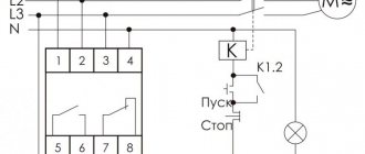
They are used in cases where the simultaneous operation of all consumers leads to an overload of the supply network (the power input is designed for less power than the power of consumers, the introduction of electricity consumption limits, etc.). Consumers are divided into two groups: priority, the disconnection of which from the power supply is extremely undesirable (computers, television and video equipment, data processing systems, etc.) and non-priority (electric heaters, various types of auxiliary equipment, electric stoves, electric kettle, etc. .). The relay operating current is set in such a way as to prevent overload of the supply network (switching off the input circuit breaker).
In relay protection devices, the most widely used are current relays, which respond to an unacceptable increase in current in the protected circuit, and minimum voltage relays, which respond to a decrease below a certain value or complete disappearance of voltage. Current relays are connected in series, and voltage relays are connected in parallel to the protected circuit. Current relay coils are made with a small number of turns from a large cross-section wire and therefore have low resistance, and voltage relay coils are made with a large number of turns from a smaller cross-section wire than current relay coils and therefore have high resistance.
An overcurrent relay operates when the current passing through its coil reaches a preset value called the operating current. When the current decreases to a certain value, called the return current, the moving relay system returns to its original position. The ratio of the return current to the operation current is called the return coefficient, which for most modern relays is in the range of 0.8-0.9.
In the instantaneous maximum current relay, current flows through the windings of coils 6 located on the poles of the magnetic circuit 7 from a current transformer connected to the operating circuit of the electrical installation or the operating current of the installation (if its value does not exceed the permissible values for the relay). When the current reaches or exceeds the value of the set operating current, the steel armature 5, under the influence of the magnetic flux, overcoming the resistance of the spring 2, will turn clockwise together with the axis, and the contact bridge 3, mounted on the axis, will close the upper pair 4 and open the lower pair of fixed contacts . The return of the movable system of relay contacts to its original position when the current in the coils decreases occurs under the action of spring 2. Lever 1 is used to smoothly adjust the operating current; in addition, the value of this current can be changed by switching the windings of the coils. When the coils are connected in series, each flows twice as much current as when connected in parallel, as a result of which the relay operating current will be half as much. - The relay does not have an adjustment of the operating time
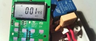
Description of the RMT 101 model
This relay is of modern design, multifunctional and is in great demand among consumers; let’s consider its technical capabilities.
Functional purpose
The relay is used to control the load current throughout the entire operating time of load devices with single-phase power supply. Current measurement limits are from 0 to 100A, the device turns off the load when the set threshold current value is reached. Each player, coming to the gaming hall, is looking for a way to save a little and reduce the cost of playing. He registers and receives a profitable welcome capital - no deposit bonuses from the casino, which come in the form of real funds or free spins. You can start the gameplay without an initial investment - use the first reward from the club for your own benefit. In order for it to be credited to your account, you need to register on the casino website, indicate and confirm the user’s personal data, and then make a request for the welcome capital. The load is connected through the relay switching contacts with a power consumption of no more than 1.75 kVA. current loads above this value up to 20 kVA are connected through magnetic starters with contacts capable of withstanding a load of the corresponding power.
Relay controls allow the user to manually set:
- Current thresholds;
- Shutdown delay time;
- Restart time after triggering;
At the same time, in addition to protection functions, the product has additional functions:
- Digital ammeter measures and displays load currents;
- Limitation of current consumption;
- A relay with load selection priority is used.
The built-in current transformer allows you to measure the current value without breaking the circuit; LED indicators on the front panel display the state of the relay and within what limits the load current is.
Main technical characteristics
| Power supply single-phase AC voltage | 220V |
| Network voltage frequency | 50 Hz |
| Current measurement range | 0-100A |
| Measurement error | 1% |
| Switching time adjustment interval | 0 – 900 sec. |
| Shutdown time adjustment interval | 0 – 300 sec. |
| Maximum switching current | 8A |
| Maximum permissible voltage | 400V |
| No load power consumption | 3.5W. |
| Wear resistance of switching contacts: - at a load of 8A - at a load of 1A | 100 thousand operations; 1 million. |
| Cross-section of connected wires in the network | 0.5 – 2mm2 |
| dimensions | 90-52,6-69,1 |
| fastening | On din - rail |
The design allows the product to function in any position in space relative to the surface of the earth.
Relay device RT40
In order to understand the principle of operation of any relay, it is possible, but not necessary, to find out what it consists of. To do this, look at the picture below and study. The source of the picture, as well as the basis for writing the article, is, in addition to personal desire and experience, issue No. 526 of the Electrician's Library (L.S. Zhdanov, V.V. Ovchinnikov - Electromagnetic current and voltage relays RT and RN).
In the figure above: a - design of the RT-40 relay; b - insulating block with fixed contacts; c - adjusting unit; g - contact unit; 1 - core; 2 - coil frame with winding; 3 - anchor; 4 — spiral spring; 5 - moving contact; 6 — left stop; 7 - right pair of contacts; 8 — left pair of contacts; 9 — insulating block; 10 — spring holder; 11 — shaped screw; 12 — hexagonal bushing; 13 — setting scale; 14 — setting indicator; 15 — upper axle shaft; 16 — shank; 17 — shaped plate; 18 — spring washer; 19 — bronze plate with a silver stripe; 20 — front stop; 21 — rear flexible stop; 22 — vibration damper; 23 - aluminum stand.
The relay consists of a U-shaped core assembled from sheets of steel. This is done to reduce stray currents.
Two coils are placed on the core. But not with copper on steel, but through plastic frames on which these same coils are wound. The beginnings and ends of the coil windings are brought out to the terminal panel, which is located on the plastic housing.
The L-shaped anchor is made of steel plate. The L-shape was chosen to reduce the size of the air gap when the relay contacts move from one position to another.
An insulating block is rigidly attached to the armature, at the end of which there are movable bridge-type contacts.
An L-shaped anchor is attached to a U-shaped bracket. Attached to the top of this bracket is a plastic drum with an aluminum lid filled with sifted sand. This part acts as a vibration damper for the moving system.
The position of the anchor is limited by left and right brass stops, which are pins.
On the sides of the relay there are relay contacts (open and closed) and the beginnings and ends of the windings. If you look at the relay, there will be odd numbers on the left (1, 3, 5, 7), and even numbers on the right (2, 4, 6, numbers. 1 and 3 are open contacts, 5 and 7 are closed contacts. Even numbers correspond to the coil terminals . The windings can be connected in series and in parallel. This regulates the maximum value of the setting. If the jumper is installed on terminals 4,6, then the scale value corresponds to the numbers printed on it. If you place the jumper on 2-4, and the second jumper on 6-8, then the scale value should be multiplied by 2. It is also worth noting that the digital symbols, as in the diagram, are not printed on the relay.
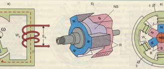
DEVICE AND PRINCIPLE OF OPERATION OF ELECTROMAGNETIC RELAY
Structurally, the electromagnetic relay is a coil that acts as a retractor.
It consists of a base made of non-magnetic material on which a copper wire is wound, which, depending on the design, may be insulated with fabric or synthetic materials, but in most cases the conductor is coated with dielectric varnish.
When voltage is applied to the coil, a metal core connected to a pusher is retracted, which drives the contacts.
Depending on the purpose, the relay contact block may consist of normally open (open) or normally closed (closed) contacts; in some cases, the contact block may combine both types of contacts.
The relay structure can be understood in more detail if you break its components into blocks:
- control - serves to convert the control signal (in our case from electric to magnetic field);
- block of intermediate elements - activates the actuator;
- executive unit - acts directly on the controlled circuit. The contact group of the device can be considered as an executive unit.
Also, when designing control circuits using electromagnetic relays, it is necessary to take into account that since the sensitive element is an electromagnetic coil, the current in the winding does not increase or decrease instantly, but over a period of time.
In this regard, possible response delays must be taken into account. It is quite small, but in some situations it can affect the operation of other elements of the circuit.
Electromagnetic relays can be classified according to the following criteria:
Areas of use:
for control, protection or signaling circuits;
control power:
low power, control signal ≤1 W, medium power, control signal ranges from 1 to 9 W, high power - signal power ≥10 W;
response time to control signal:
inertia-free reaction time ≤ 0.001 sec., fast-acting - reaction time from 0.001 to 0.05 sec., slow reaction time from 0.05 to 1 sec., as well as time relay with adjustable response delay.
the nature of the control voltage:
DC - neutral, polarized and alternating current.
It is worthwhile to dwell on the features of DC relays. As mentioned above, they are divided into neutral and polarizing. The main difference between these two groups is that polarizing devices are sensitive to the polarity of the applied voltage, that is, the movable core changes its direction from right to left or vice versa depending on the polarity of the voltage.
DC electromagnetic relays are divided into:
- two-position;
- two-position with dominance;
- three-position or dead zone relays.
The operation of neutral type devices does not depend on the polarity of the supplied voltage. The disadvantages of relays using direct current as a control signal include the need to install power supplies to supply direct current and the high cost of the device itself.
AC relays do not have this, but they also have their drawbacks, such as the need to modify the design to eliminate vibration of the core.
The operating parameters are worse than those of devices using a linear control signal, namely - worse sensitivity, much less electrical force. But at the same time, they can be directly connected to the AC electrical network.
Design and operating principle
The DC relay consists of the following elements:
- Electromagnet;
- Contacts;
- Anchors;
- Springs;
- Branches for connection to the network.
When the regulator is connected to the network, the coil begins to receive electrical energy. After this, the armature is attracted to the metal core and the contacts fly over. At the same time, the contacts of the devices connected to the relay circuit close. Moreover, if electric current is not supplied (for example, in the absence of electricity) or is supplied, but unevenly (surges are observed in the network), then the contacts of the connected devices are pulled upward, after which the circuit opens.
Photo - drawing
The effect may vary depending on the design and purpose of the device. For example, solid-state relays (SSR) of the KIPPRIBOR type contain additional power switches based on triacs and thyristors in their design, which increases their efficiency. Separately, it is necessary to note the throughput, because there are devices designed for low and high currents.
Photo - design
Characteristics of species
Current relays can be divided into primary and secondary. The first type is more common in switch designs. It is used in an electrical network whose voltage is no more than 1 thousand V.
Secondary relays are activated by a current transformer, which is connected to the power cable. The transformer reduces the current to a value that is suitable for normal operation of the device. The secondary type of relay can be divided into the following subtypes:
- induction;
- electromagnetic;
- differential;
- integrated circuit device.
Electromagnetic relays can be neutral. They react equally to direct current that passes through the winding. According to the direction of movement of the armature, such relays are divided into angular devices with armature movement and with an armature that retracts. The electromagnetic device consists of the following elements:
- contacts;
- core;
- anchor;
- pin;
- yoke.
To keep the armature at a great distance from the core, special springs are used. As soon as a signal arrives at the winding, a magnetic force is generated and the armature is pressed against the core. This causes some contacts to close while others open.
The second type of electromagnetic devices is polarized devices. Their main difference is the presence of two windings and cores, as well as constant contact traction.
The electromagnetic type device has the following advantages:
- affordable price;
- no need for cooling;
- slight heat generation;
- immunity to interference that may occur due to a lightning strike.
Such models have their drawbacks. These include low speed of operation and the formation of radio interference during operation of power contacts.
Differential models compare pre- and post-consumer understatement. The consumer can be a power transformer. If it operates in normal mode, then the current in it is always almost the same. However, if there is a short circuit, the balance is upset. Then the device completely closes the contacts.
Differential type devices are most often used in household appliances. They help prevent current leakage from wires or devices. Most often, the following household appliances are protected in this way:
- lamps;
- office equipment;
- boilers.
What is a time relay, what is it used for and where is it used?
This device, designed to turn an electrical circuit on and off automatically, after a certain time interval, is used in electrical engineering and more often in everyday life. Based on the principle of operation, they are divided into the following types:
- Electromagnetic
- Pneumatic
- With clock mechanism
- Motor
- Electronic
In electrical engineering, there are also interval relays; they are used to create an interval switching on of a circuit with a certain time delay after a given signal, when it is necessary to switch on at an interval after switching on or off.
Household appliances are mechanical and electronic. Today on the market you can more often find electronic devices with a wide range of functions. The design is a simple circuit with a magnetic coil and a contact group; the main difference from other devices is the built-in integrated circuit that controls the power supply to the coil.
In mechanical devices, the integrated circuit is replaced by a special mechanism resembling a rotating disk. Due to the rotation of the disk and the movement of special marks on it, the circuit is turned on or off at a certain time.
A time relay is an incredibly useful device that has found its application in many areas of life; it is actively used to control the power of electrical appliances from 220V, control ovens, heated floors, washing machines, heating and air conditioning systems.
For example, when you need to turn on the power supply to a water pump in your country house to collect water without your participation and turn it off in time to protect it from running dry. Or completely cut off the power grid at certain hours in order to save electricity.
Operating principle of the electromechanical relay RT40
Having familiarized ourselves a little with the components of the relay and their purpose, we will understand the principle of operation of the device. The principle itself can be seen in the illustration below.
The operation of the PT40 relay is based on an electromagnetic system with a transverse armature. The current passes through the relay windings and creates a magnetic flux F. The magnetic flux is closed through the core and armature. The armature is magnetized. The magnetic poles of the armature and core are directed in opposite directions. As a result, a force Fel arises, which attracts the armature to the core.
If you change the direction of the current to the opposite, the armature will still be attracted, since the poles of both the core and the armature will change. That is, the operation of the relay does not depend on the direction of the current and it can operate both continuously and alternatingly.
Mpr is a counteracting moment, which always exists and depends on the degree of compression of the spring. When current is passed, an electric torque is created that attracts the armature to the core. When the opposing and electric moments become equal, the armature begins to move and the bridge with contacts moves from the making contacts to the opening ones. That is, by adjusting the setting in the relay, we change the counteracting torque and thereby increase or decrease the required current to operate the relay.
The resistance of the relay is significantly lower than the resistance of the network to which it is connected, so rt40 does not have a significant effect on the current value.
Advantages and disadvantages
Like any element, relays have their advantages and disadvantages, however, despite the disadvantages, in some cases it is simply impossible to do without the use of these devices.
pros
- Simple design
- Easy to repair, you can always disassemble it to clean contacts or replace individual elements
- Low contact resistance
Minuses
- Limited resource due to mechanical elements used
- Contacts sometimes burn out
- Low speed when triggered, unlike semiconductor elements, a mechanical device is a hundred times slower than an electronic device, but the trigger speed is still quite high
- Possible contact rattling if there is insufficient voltage on the coil
- Clicking noise when switching
Electromagnetic relays on diagrams: windings, contact groups
The peculiarity of the relay is that it consists of two parts - a winding and contacts. The winding and contacts have different designations. The winding graphically looks like a rectangle, the contacts of different types each have their own designation. It reflects their name/purpose, so identification problems usually do not arise.
Types of electromagnetic relay contacts and their designation in diagrams
Sometimes a type designation is placed next to the graphic image - NC (normally closed) or NO (normally open). But more often the relay affiliation and the number of the contact group are specified, and the type of contact is clear from the graphic image.
In general, you need to look for relay contacts throughout the entire circuit. After all, it is physically located in one place, and its different contacts are part of different circuits. This is shown in the diagrams. The winding is in one place - in the power supply circuit. The contacts are scattered in different places - in the circuits in which they work.
An example of a circuit using electromagnetic relays: the contacts are in the corresponding circuits (see color coding)
For an example, look at the relay diagram. Relays KA, KV1 and KM have one contact group, KV3 - two, KV2 - three. But three is far from the limit. There can be ten, twelve or more contact groups in each relay. And the diagram in the figure is simple. And if it takes up a couple of A2 sheets and there are a lot of elements in it...