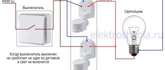
What is a light sensor and what is it for? This device has many names, for example, light sensor, light control switch, twilight switch, photosensor or photo relay. It is intended exclusively for saving electrical energy and is a small device with various microcircuits inside, connected to an electrical circuit.
Nowadays, there are a huge number of various devices of this type. For example, a motion sensor that closes a circuit when there is movement in its field of activity. An individual feature of the photo relay is the ability to change the power of artificial lighting depending on the level of natural light. Recently, these sensors have become increasingly popular and are widely used together with lamps for street lighting at night, with lighting fixtures in staircases, etc.
In this article we will talk about how to connect a photo relay, and a detailed diagram of connecting a photo relay for street lighting will be presented.
The principle of operation of the twilight switch and its connection diagram
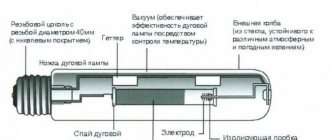
This device has a simple structure. A special part called a photosensitive element is installed inside it. Usually this is a photodiode or photoresistor. Each of these elements is capable of increasing or decreasing the resistance inside the sensor, based on the level of natural light. This process causes the voltage inside the photo relay to increase or decrease, and the lighting device begins to produce artificial light or turns off.
In simple words, the light sensor works like a switch, but this happens automatically. The amount of luminous flux at which the photo relay (switch on sensor) is triggered is adjusted manually and does not require special knowledge.
Design features of light sensors
These devices have similar design features. As a rule, sensors are a small plastic box that is mounted on the wall or on the body of the lighting fixture itself.
Installing a photo relay takes little time and allows you to save a sufficient amount of electrical energy. The twilight sensor pays for itself in the shortest possible time.
Connecting a photo relay for street lighting in high-power conditions requires minor changes during the installation process. In this case, the device is connected via a magnetic starter.
If it is planned to install several light sensors, then they are connected in parallel.
There are also devices that have a remote sensor. This design feature allows you to install the lighting device together with a photo relay in places out of reach of natural light.
Modern technologies do not stand still, and the lighting control scheme changes along with them. Light brightness adjustment, lighting time and other indicators can be adjusted and maintained automatically via a computer and the Internet.
Photo sensor connection diagram
The figure shows a generalized standard diagram for connecting a light sensor. Manufacturers of these devices are constantly improving the design and making adjustments to circuits and operating modes. It all depends on the ratio of the cost of the photo relay to the quality of its manufacture.
Determining the location
In order for the equipment to function properly and to eliminate the possibility of false alarms, it is necessary to carefully approach the issue of choosing the location of the sensor. It is important to consider the following criteria:
- protect the device from external factors that may cause the light to turn on;
- providing a detection zone that matches the volume of the room;
- ensure correct connection of the motion sensor to the electrical wiring;
- It is not recommended to install equipment near heating radiators or hot water pipes;
- Thermal or electromagnetic devices may emit interference that may adversely affect the operation of the device.
Choosing the correct sensor location based only on theoretical knowledge and without practical experience is quite problematic. It is necessary to carefully approach this issue, study the literature and consult with specialists.
Expert opinion
It-Technology, Electrical power and electronics specialist
Ask questions to the “Specialist for modernization of energy generation systems”
With a halogen lamp In conclusion, I recommend using an extended switching circuit for the motion sensor, which allows you to control such a sensor as you wish. Ask, I'm in touch!
Principles of measuring light levels with a twilight sensor
The installation diagram for a photo relay sensor for street lighting was described above. But how does the photo relay determine the moment when it is necessary to close or open the electrical circuit? These devices use sensitive elements made of various semiconductor metals, which are mounted at the location of the sensor where natural light falls. At the point of contact of these metals, a small electrical impulse occurs, which gives a further command to close the entire circuit. Let's consider the main types of these elements (the principle of their operation):
- photoresistor (resistance changes depending on the surrounding natural light flux due to the content of cadmium sulfide or selenide inside the element);
- photodiode (capable of generating an electrical charge using the photovoltaic effect);
- phototransistor (is an optoelectronic conductor that responds to natural illumination by irradiating part of its base);
- photothyristor (used in circuits with direct current, regulates voltage based on the natural beam of light incident on its matrix);
- phototriac (operates from alternating current, synchronizes the supplied current from several channels, for example, from 2 photothyristors, and transmits it to the main electrode, which controls the entire circuit).
The principle of operation of a photocell in lighting networks
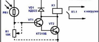
In order to understand what a photo relay is in a lighting line, you can consider the simplest circuit, where standard photodiodes, photoresistors or phototransistors are used as a photocell with the designation “PV” on the diagram. Standard lighting schemes, as a rule, provide an analogue type of response, which has the ability to set gradation or sensitivity to the level of natural light.
Modern circuits with photo relays (PR) consist of the following important parts:
- The sensitive detector itself or FE.
- A threshold comparator in a modular design, or in the form of an independent microcircuit, or, less commonly, on discrete components.
- A power or switching element, most likely triacs or relays, switching on an electrical load.
Operating principle of the FR:
- Installation of photo relays in the lighting system is carried out according to the scheme defined by the manufacturer.
- When light hits the receptive area of the PV, its electrical conductivity changes.
- The change in electrical conductivity from the standard value is recorded by an electronic module, which is pre-configured to work together with a photo relay.
- This unit plays the role of a comparator, which is able to turn on only when the lighting threshold is reached.
- Subsequently, the comparator will send a control electrical signal to the execution module, which turns off the supply voltage to the flashlight.
- After completing the on-off cycle, the street lamp with photo relay goes into the off position until dusk.
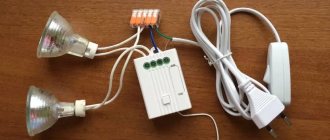
A visual step-by-step process of connecting a flashlight to a photo relay on a regular stand
The connection diagram for a light sensor for street lighting in a small area will be described below. To do this, we need a lamp, previously screwed into the socket, and the photo relay itself.
For greater clarity, we will install it on a stand. To do this, we attach a light sensor and a lamp in a socket next to each other, which will symbolize the lamp.
Next, you should connect the zero and input phases to the light sensor itself (as a rule, the connection points are marked on the body).
By inserting special rubberized plugs into these holes, you can connect the wires. These rubber plugs provide good protection from dust and other harmful external influences.
“Expert tip”: the connection points of the input wires should be directed downward when installing the sensor, which will increase protection from moisture and dust.
Before connecting, we clean the ends of the wires well (about 1 cm).
Next, connect the wires to the sensor in the following sequence:
- input phase;
- zero phase;
- protective phase (grounding).
The wires are connected to the lighting fixture itself in a similar way. We connect the input and zero phases to the socket, and the grounding phase is connected to the body of the device for lighting.
The last step will be to adjust the sensitivity of the regulator of our photosensor. This completes the installation process; all that remains is to replace the protective cover and tighten the bolts.
This is what the entire procedure for connecting a light sensor and lighting device to an electrical circuit looks like. It is not anything complicated, you just need to follow the correct order of connecting the wires. Otherwise, you can get negative consequences, including a short circuit or even a fire.
The procedure for connecting a photo relay for street lighting to diode light sources or spotlights is similar to that described above and is not particularly difficult.
Varieties
Based on the type of sensors used, they are divided into several groups:
- Infrared. They are triggered by heat in the field of operation of the sensor. Since domestic animals, in addition to humans, are warm-blooded, infrared detectors can also react to them.
- Acoustic. React to noise. If the doors open with a creak, or there are loud footsteps, the sensor will trigger.
- Microwave. Active type sensors. They themselves form waves in the microwave range and track their return back. If there is a difference from a moving object, the electrical circuits are closed/opened.
- Ultrasonic. The operating principle is similar to microwave sensors, but they are rarely used in practice. Pets may react inadequately to ultrasound.
- Combined. Several types of motion detection can be combined in one lighting device. More reliable systems, but also more expensive.
- Astronomical timer. New generation relays. It also controls the operation of lighting devices, but is based on a different control principle. The microcomputer of the astro-timer contains a program with data on the time of movement of the sun in different regions of the planet. In order to set up the device, you need to enter the GPS data of your locality and the current date and time into the device. Based on these key settings, it will automatically determine when it's time to turn on the lights. If false alarms are possible with a photo relay, then the astro timer does not have such errors. It works in any weather.
Typically, an infrared light sensor is used for a street lamp, as it has a number of advantages:
- inexpensive;
- with a large range;
- can be easily adjusted to suit your preferences.
Street or staircase detectors predominantly use either ultrasonic or microwave detectors. Capable of reacting at a sufficiently large distance from the light source. Microwave - can react even if the person is still behind the barrier.
There is also a classification of automatic lighting devices for street lighting according to the type of photo relay design.
- All lamp control elements are located in one housing. This design is more voluminous, but also quite convenient - there are no unnecessary wires. You just need to attach it next to the lamp.
- The “day” sensor itself is mounted outside, and the control relay with the lamp is located in a separate panel inside the room. Thus, all elements of street lighting regulation are thoroughly protected from weather disasters.
The sensitivity of the devices can be adjusted. The regulators are located at the bottom of the case and are signed with “+” and “—” signs.
It is better to work with adjusting the light sensor when it gets dark and when it is installed and connected to the network.
By turning the screw towards the minus sign, the sensor loses its sensitivity. And the relay will start to operate only in complete darkness. And accordingly, by turning towards the plus, the sensitivity increases.
When all the manipulations are completed and the result of the work is positive, the photo relay setup will be completed.
In addition to such adjustable photo relays, there are the same devices, but supplemented with a motion detector. The flashlight will not turn on in the dark until the detector reacts to the movement of a person in its area of influence.
Technical characteristics of twilight switches
The main parameters for the operation of photo relays are specified in GOST standards and technical documentation of devices. These indicators were selected taking into account the realities of use in our country, however, there are analogues of these light sensors on the market. Before purchasing a device, you should definitely make sure that the device will work correctly when connected to our electrical circuit.
Main characteristics of light sensors:
- the value of the rated supply voltage;
- power indicators of electrical energy consumption and the level of thermal load on the lighting device;
- operating conditions in certain climatic zones (precipitation, dust, high or low ambient temperature, etc.);
- light sensitivity indicators;
- varieties and types of devices (switched, fluorescent and energy-saving).
How can you adjust the detector?
In modern motion sensors (MS), you can adjust the sensitivity, illumination, delay time for turning off the light and installation angle.
All these parameters, when properly configured, can save up to 50% of energy, which is a very significant figure. However, it should be immediately noted that not all motion sensors have three controls. In older models, you can adjust only two parameters - delay time and sensitivity, or delay time and light level, as in the photo below:
We recommend viewing the instructions, which explain how the detector works:
Now we will look separately at how to set up a motion sensor on a spotlight or other type of lamp.
Disadvantages of Twilight Switches
Along with the undeniable advantages, photo relays also have a number of significant disadvantages, which are also worth mentioning in this article.
Unlike a motion sensor, light sensors are not able to illuminate a specific place at the right time. The light comes on on all lighting fixtures at once, and the lighting occurs in a not entirely rational way. Only one lamp can work or all at once.
These devices are very sensitive to external influences and weather conditions. They especially often react negatively to ordinary dust. Also, the device may not respond quite adequately when there is a sudden change in the weather, for example, when dark clouds come in, it may “think” that night has fallen and turn on the lights.
Photo relays with adjustable lighting levels are distinguished by their high price tag compared to their analogues.
Pros and cons of using an outdoor photo relay
The main advantage of the daylight sensor is tangible energy savings. The undoubted advantages of systems using photocells are:
- The device operates at low currents.
- Instant on/off.
- High performance.
- There are no rubbing mechanical parts, which increases the durability of the device.
- Long period of operation.
But it should be borne in mind that the device is not designed for use in extreme conditions. Therefore, you should carefully monitor its tightness. Ingress of moisture can, if not completely disable the sensor, damage it by causing oxidation of the relay contacts.
A dirty and dusty sensor will also not function properly. The entire device must be kept clean at all times.
How to set up a motion sensor for an indoor lamp
By purchasing a detector to trigger a luminaire in response to detecting movement of an object within the coverage area, one configures it to suit specific operating conditions. However, let's look at how to configure a motion sensor for indoor lighting in a general situation:
- Install and connect the sensor in accordance with the manufacturer's instructions and electrical installation rules.
- Adjust viewing angle.
- Test the device with factory settings.
- Make adjustments, if necessary, by tightening the regulators.
Electronic photosensor Camelion LXP-02
One of the types of electronic photosensors Camelion LXP-02 (2200W), like similar devices, controls lighting throughout the day without outside participation.
Device parameters:
- The maximum sensor load power level is 2200 Watt;
- Sensor illumination level - 100 lux;
- Mains voltage level - 230 V / 50 Hz;
- Current - no more than 10 A;
- The color scheme of the case is white;
- The presence of a light indicator is absent;
- Weight - 160 gr.
When using this photosensor, you should not expect it to respond to directional light of short duration (a few seconds). The same applies to dimming the sensor; the switching will not happen immediately, but only after some time.
In addition, this photosensor does not have sensitivity adjustment of the device, which means the switching moment will depend on where exactly the sensor is located.
By the way, you can find out about direct control of light by a power semiconductor device here.