For a comfortable stay today, many houses and apartments use automated systems with electronics. You may have already heard about pass-through and main switches: they help assemble a lighting control circuit in several places. Despite the practicality of the principles of operation of such a system with wiring, as well as its connection, it is not a very simple matter. However, there is a simpler option - the use of an interesting bistable device, which is otherwise called a pulse relay.
Purpose, operating principle and application
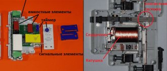
A classic pulse relay, like a regular one, consists of a coil with a core, a moving system and a contact group. Such a device is often called bistable - because it has two stable states: with the contacts turned off and with the contacts on. The relay state is maintained when the voltage is removed, and this is the main difference from the traditional system.
Bistable electromagnetic relay.
In real designs, the prolonged presence of voltage on the coil is considered unnecessary and even harmful - the winding may overheat. Therefore, such a device is controlled by short pulses:
- the first pulse closes the contacts;
- the second opens;
- the third closes again and so on.
Each impulse throws the contacts into the opposite state. Pulses are generated by switches. It is logical to make the switching device in the form of a button without locking in the pressed position.
Push-button switches.
An ordinary keyboard device is of little use here - it is easy to forget it in the on position, and after a while the coil will fail. Instead of switches, you can use buttons for doorbells .
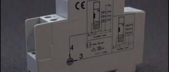
Designation on the diagram and diagram of the device operation.
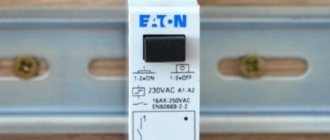
A typical relay has inputs:
- A1 and A2 – for connecting 220 volt power;
- S – control input;
- NO, C, NC – contact system terminals.
There is no single standard for the designation of terminals. Input markings may vary from manufacturer to manufacturer.
In fact, the switching does not occur synchronously by pressing a button - the system waits for the nearest transition of the sinusoid through the zero value. This is done so that the switching current is zero, which extends the life of the contact group. But such a transition occurs twice per period, the maximum delay is 0.01 seconds, so the short pause is unnoticeable.
Many pulse relays for controlling electric lighting have additional on and off inputs. They have priority over the S input - when voltage is applied to them, you can force the relay to turn on or off, regardless of the state at the S terminal.
A pulse switch can be used to create lighting control systems in which lights can be turned on and off from several places, independently of other switching devices. Classically, such circuits are built on pass-through and crossover switches, but the use of pulse switching devices has its advantages.
Answers to the 5 most common questions
How does an impulse relay work?
Electromechanical relays are equipped with mechanical contacts and a control coil. The contacts close when a signal is applied to the coil (to do this you need to press the switch button), and after the signal stops they remain in the closed position.
What load can be connected via IR?
About 220 V or 16 A.
How does a relay change a lighting system?
It allows you to control lighting from different switches. All you have to do is press a button to record one state. When pressed again, the mechanism opens and remains so until the next impulse.
What are pulse relays made of?
Electronic relays are equipped with a relay output or a semiconductor switch. The basis of the functionality is microcontrollers that monitor the supply of signals and control switching. Turning on and off is done by applying current to the semiconductors.
What are the 2 main principles of relay design?
The first is using a solenoid (current-carrying coil), the second is using two opposing coils.
Main technical characteristics
When purchasing a device, you need to pay attention to the main parameters:
- contact group power;
- supply voltage;
- coil actuation current;
- design of the contact group (closing-opening or changeover);
- additional service functions.
You also need to pay attention to such a parameter (illogical at first glance) as the number of connected switches. It would seem that the characteristic is absurd, but we must take into account the widespread use of devices with backlight chains. If there are a lot of them, then the resulting total current through these circuits will be sufficient to trigger the relay.
The control voltage for most devices is 220 volts, but there are also relays with low-voltage control (12..36 volts). Such devices have a huge safety advantage, but require an additional power source. Therefore, such devices are not widely used in everyday life (as opposed to in production).
Through the control circuit, bistable switching devices consume very little current (this power consumption has virtually no effect on the electric meter readings). This fact makes it tempting to make control circuits with wires of reduced cross-section (up to 0.5 sq. mm). It should be remembered that to protect such conductors, it will be necessary to install a separate circuit breaker with a lower operating current in the switchboard. Feasibility is decided on a case-by-case basis.
Second installation option
Can you connect the impulse relay yourself?
Yes, I can do it myself No, I don’t understand
When using this option for connecting relays to switches, fewer wires will be required, and their cross-section can be smaller - from 0.5 mm2. In this case, another protective device is needed. This connection option is used less often than the first. Detection of faults in the circuit is simplified here by the use of two machines designed for 6 and 10 amperes.
Types of pulse relays, their disadvantages and advantages
Bistable switches can be produced in two versions:
- classic electromechanical (available in a housing for mounting on a standard DIN rail);
- modern electronic.
The second option allows you to reduce the size, increase the reliability of the device, and also allows developers to implement almost unlimited service functions (switch-off delay timers, control via Wi-Fi, etc.). The disadvantages of pulsed electronic light switches include low noise immunity .
Electronic impulse relay.
A classic electromechanical relay is insensitive to interference and interference , but it operates noisily - constant loud clicking can be annoying.
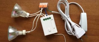
Various pulse relay connection diagrams
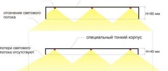
The simplest diagram of a lighting system on a bistable device looks like this:
Connection diagram for a simple bistable device.
If the switches are not backlit, then their number can be infinite . In fact, there is a limitation on the installation range - at a certain cable length, the resistance of the conductors can limit the current required to turn on the relay. But for reasonable distances this limitation is theoretical. The number of lamps connected in parallel is limited by the load capacity of the output contact group.
| Relay name | Type | Load capacity of contacts, A |
| MRP-2-1 | Electromagnetic | 8 |
| MRP-1 | Electromagnetic | 16 |
| BIS-410 | Electronic | 16 |
| RIO-1M | Electromagnetic | 16 |
| BIS-410 | Electronic | 16 |
The table shows that many relays allow loads from 1760 to 3520 W. This is enough to cover almost all reasonable lighting needs (especially given the proliferation of LED equipment) without the use of intermediate relays.
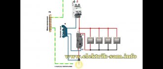
Another circuit option is to use priority inputs for switching on or off. This principle is used when it is necessary to provide centralized control of the lighting of several rooms or zones. When manipulating the central control buttons, the state of the lamps will not depend on the previous position - all lamps can be turned on or off at the same time. Such two-channel switching allows you to turn on or off the light in all rooms at once from one place, and then control the light from local buttons.
Scheme of switching on the device with priority control inputs.
Installation of a pulse device of the electromechanical type is carried out in a switchboard - it is most convenient to mount a DIN rail there. The topology of laying cable products is considered using a simple diagram as an example, and it looks like this:
Laying cables when placing a relay in a switchboard.
Some connections are made by wires in the distribution board. You will also need:
- a five-core cable for laying from the switchboard to the junction box (in the absence of a PE conductor - four-core);
- three-wire to the lamp or group (two-wire if there is no PE);
- push-button switches are connected via a two-core cable.
Switch instead of master button
The most basic load sharing is organized using an additional switch in the electrical panel. No, not like that
It is also called a load switch.
The scheme here is the simplest, it doesn’t even require a separate single-keyboard:
Error No. 1 It is important that the switch be rated higher than or equal to the current of the input circuit breaker.
Since it does not have its own protection and if the load is exceeded, it will simply burn out.
Before leaving on vacation, you open the switchboard, turn off this switch without touching the input circuit breaker, and calmly leave the house.
Despite its simplicity, this scheme has one significant drawback. Not everyone has a switchboard located right next to the front door.
In private homes, it can generally be hidden in the basement. Imagine, you turned off the switch and all the lights, and then let’s get out into the street in the dark.
And so every time you leave your home. It's also extreme and convenient.
Impulse relay or crossover switch
A control circuit from three or more places can also be organized using two pass-through devices and several (according to the number of required posts) cross devices.
Laying cables when using pass-through and crossover switches using a junction box.
The cable routing in this case looks like this (PE conductor not shown). Obviously, in this case, all switches are connected to each other by a cable of three wires versus two.
Laying cables in a loop when using pass-through and crossover switches.
You can do without a junction box and make connections using a cable. In this case, taking into account the protective conductor, the number of conductors in the communication cables increases to 4. Another disadvantage of this installation is that the N and PE conductors have many connection points, which reduces the reliability and safety of the circuit.
Therefore, a circuit with a pulse relay is more economically advantageous, although it is not very common. And the greater the distance between the switches, the greater the benefit. In addition, the full load current of the consumers passes through the pass-through switch, and when the circuit is implemented on impulse devices, only a small control current is switched - the durability of the buttons will be clearly higher. When designing a lighting system, you need to pay attention to this option.
How to avoid errors at 3 levels when connecting I.R. to the electrical panel
Inexperienced specialists have difficulty connecting a pulse relay because they do not know in what sequence the elements are connected to each other. The more switches used, the more complex the final job. However, in reality, if all the requirements are met, there can be an almost unlimited number of control buttons. The specialist is faced only with the correct placement of pulse relays.
In this case, the electrical panel will consist of different levels:
- Lighting protection by automatic RCD.
- Automatic for protecting several light groups.
- Pulse relays.
With the first level of installation of RCDs in individual rooms, everything is clear - a typical electrical panel assembly diagram. Next come automatic circuit breakers for light groups that protect lamp cables and control cables. The next level is pulse relays. It must be remembered that a separate relay is installed for each light group. First, according to all the rules, a regular electrical panel is assembled, which ends with a machine. And pulse relays are connected to these machines, which are responsible for supplying electricity to individual rooms.
Typically, the general light and sconces in the room are controlled by separate switches. If you install the relay in accordance with the above sequence, then with the help of one switch it will be possible to control an entire group of lights at once. This scheme is increasingly used in modern homes because it is convenient and practical. Individual light sources may have their own switches and one common one.
Working in non-standard situations
Such situations, first of all, should include moments when the electricity in the apartment is completely turned off. When it is restored, the relays behave differently:
- For devices of an electromechanical system, removing the supply voltage does not lead to switching, therefore, when power supply appears, the lighting will be in the state in which they were caught when the power supply disappeared. If the light was turned on, it will turn on again, if it was turned off, it will remain turned off;
- electronic devices with non-volatile memory will behave in the same way;
- simple electronics without memory will reset the state to the position provided by the developers - usually to the off position (but sometimes to the on position).
Another possible collision is the simultaneous pressing of two buttons in different places. The system will perceive this as one click, regardless of the design of the relay, and will move the contact group to the opposite position.
We recommend viewing: Using relays to control lighting in the house.
The use of pulsed devices allows you to build convenient lighting control schemes that allow you to turn on the lights only when people are at the site. This provides significant savings on electricity. Also, such schemes make it possible to increase the comfort of operating utility networks. In many cases, their use is justified from an aesthetic point of view.
Examples of effective use
Various device options are available for sale, including relays with a timer. They are able to automatically turn off the lighting after a certain period of time. There are mechanical and electronic models to choose from, with a wide range of applications.
Relays with solenoids or coils cannot be used independently due to their design. Control is performed externally using switches with buttons or keys. It differs from the standard one in that it has only one stable position. It is enough to press it once to activate the relay, after which it returns to its original position. When pressed briefly, the circuit is closed, and this is enough to trigger the relay coil.
This feature allows you to connect an unlimited number of switches to one coil. This allows you to solve any problems regarding the placement of light sources and other electricity consumers. There are also no restrictions on the specific installation location of the pulse relay.
Pulse relays have a wide range of applications due to some features:
- Low current, so any power button is suitable.
- The presence of an indicator to check the status of the electrical network.
- Numerous options for every situation.
Modern single-position switches are equipped with an LED that acts as an on indicator. One glance at it is enough to check the lighting condition. Thanks to this, pulse relays can be located even in remote places where the room itself is not visible. Specialists will help you choose a specific model depending on operating conditions.
Manufacturers offer a wide range of switches, differing in design features and design. The differences relate to the following aspects:
- Mortise and overhead layout methods.
- Extensive color palette.
- One-, two- and three-button design.
Pulse relays with two or three buttons are capable of controlling lighting in different electrical networks. From one place you can turn off or turn on several groups of lighting fixtures at once. Such devices are installed to control lights, blinds and other electronic elements. Thanks to the variety of designs, it is also possible to choose the appropriate option for a specific interior.
Different types of relays