Electricity
Electric current (I) is the directed movement of free electric charge carriers.
In metals, free charge carriers are electrons; in plasmas and electrolytes, they are ions. The unit of current measurement is ampere (A). Conventionally, the positive direction of current in the external circuit is taken to be the direction from a positively charged electrode (+) to a negatively charged one (-).
Get a decision on TOE
If the direction of the current in the branch is unknown, then it is chosen arbitrarily. If, as a result of calculating the circuit mode, the current has a negative value, then the actual direction of the current is opposite to the arbitrarily chosen one.
AC period and frequency
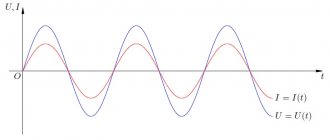
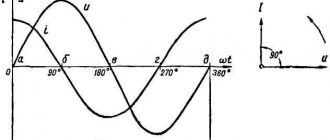
The time during which one complete change in the emf occurs, that is, one cycle of oscillation or one full revolution of the radius vector, is called the period of alternating current oscillation (Figure 1).
The period is expressed in seconds and denoted by the letter T.
Smaller units of measurement of period are also used: millisecond (ms) - one thousandth of a second and microsecond (μs) - one millionth of a second.
The number of complete changes in the emf or the number of revolutions of the radius vector, that is, in other words, the number of complete cycles of oscillations performed by alternating current within one second, is called alternating current oscillation frequency .
Frequency is designated by the letter f and is expressed in cycles per second or hertz.
One thousand hertz is called a kilohertz (kHz), and a million hertz is called a megahertz (MHz). There is also a unit of gigahertz (GHz) equal to one thousand megahertz.
1000 Hz = 10 3 Hz = 1 kHz;
1000 000 Hz = 10 6 Hz = 1000 kHz = 1 MHz;
1000 000 000 Hz = 10 9 Hz = 1000 000 kHz = 1000 MHz = 1 GHz;
The faster the EMF changes, that is, the faster the radius vector rotates, the shorter the oscillation period. The faster the radius vector rotates, the higher the frequency. Thus, the frequency and period of alternating current are quantities inversely proportional to each other. The larger one of them, the smaller the other.
The mathematical relationship between the period and frequency of alternating current and voltage is expressed by the formulas
For example, if the current frequency is 50 Hz, then the period will be equal to:
T = 1/f = 1/50 = 0.02 sec.
And vice versa, if it is known that the period of the current is 0.02 sec, (T = 0.02 sec.), then the frequency will be equal to:
f = 1/T=1/0.02 = 100/2 = 50 Hz
The frequency of alternating current used for lighting and industrial purposes is exactly 50 Hz.
Frequencies between 20 and 20,000 Hz are called audio frequencies. Currents in radio station antennas oscillate with frequencies up to 1,500,000,000 Hz or, in other words, up to 1,500 MHz or 1.5 GHz. These high frequencies are called radio frequencies or high frequency vibrations.
Finally, currents in the antennas of radar stations, satellite communication stations, and other special systems (for example, GLANASS, GPS) fluctuate with frequencies of up to 40,000 MHz (40 GHz) and higher.
Electromotive force
Electromotive force E (EMF) characterizes the ability of an induced field to cause an electric current. The unit of measurement is volt (V). Energy sources can be sources of emf and current. This manual only discusses emf sources. The EMF source is characterized by two parameters: the values of the EMF (E) and internal resistance (r0). An EMF source whose internal resistance can be neglected is called an ideal source. A real EMF source has a certain value of internal resistance. At the EMF source, the internal resistance is significantly less than the load resistance (RH) and the electric current in the circuit depends mainly on the magnitude of the EMF and the load resistance. The EMF source has the following graphic symbols.
The current-voltage characteristic of the EMF source has the form:
Rice. 1
The relationship between the voltage at the source terminals and its EMF has the form:
U = E – r0× I (for a real EMF source)
U = E (for an ideal source).
Electrical resistance R is a value characterizing the resistance of a conducting medium to the movement of free electrical charges (current). The unit of measurement is Ohm. The reciprocal of resistance is called electrical conductivity G. The unit of measurement is siemens (Cm).
General electrical engineering questions
Study questions
- Definition and Meaning of Electrical Engineering
- Electric circuit and its elements
- Electrical circuits of direct and alternating current.
General electrical engineering questions
Electrical engineering
- a field of science and technology that uses electrical and magnetic phenomena for practical purposes.
The history of the development of this science takes two centuries.
It began after the invention of the first electrochemical source of electrical energy in 1799. It was then that the study of the properties of electric current began, the basic laws of electrical circuits were established, electrical and magnetic phenomena began to be used for practical purposes, and the first designs of electrical machines and devices were developed. The life of a modern person without the use of electrical energy is unthinkable. The ever-increasing need for the use of electrical energy has led to the problem of its centralized production, long-distance transmission, distribution and economical use. The solution to the problem led to the development and creation of three-phase electrical circuits. Enormous credit for the creation of elements of such circuits belongs to the outstanding Russian scientist M.O. Dolivo-Dobrovolsky. He created a three-phase asynchronous motor, a transformer, and developed four-wire and three-wire circuits (1891).
Today, electrical energy is used in communications technology, automation, measuring technology, and navigation. It is used to perform mechanical work, heating, lighting, and is used in technological processes (electrolysis), in medicine, biology, astronomy, geology, etc. Such an extensive penetration of electrical engineering into human life has led to the need to include it in general technical disciplines in the training of specialists of all ages. technical specialties. At the same time, the main task for students is to familiarize themselves with and assimilate the physical essence of electrical and magnetic phenomena. This will allow you to understand the principles of operation of electromagnetic devices and operate them correctly.
Electric circuit and its elements
In the theory of electrical engineering, an electrical device and the physical processes occurring in it are replaced by a calculated equivalent - an electrical circuit.
Electrical circuit
is a set of electrical energy sources and loads connected to each other by conductors through which electric current can flow. Electromagnetic processes in an electrical circuit can be described using the concepts of current, voltage, emf, resistance, conductivity, inductance, capacitance.
Electric current can be direct or alternating.
Permanent
called a current that does not change over time. It represents the directed, ordered movement of electric charge carriers. As you know from a physics course, charge carriers in metals are electrons, in semiconductors electrons and holes (ions), in liquids – ions.
The ordered movement of charge carriers in conductors is caused by an electric field
. The field is created by sources of electrical energy. The source converts chemical, mechanical, kinematic, light or other energy into electrical energy. It is characterized by EMF (electronic motive force) and internal resistance. The source emf can be constant or variable over time. The EMF variable can change over time according to any physically realizable law. The current flowing through the circuit under the influence of variable EMF is also variable.
Direct current is usually denoted by the letter I,
- variable i(t);
- constant EMF – E,
- variable e(t),
- resistance – R,
- conductivity -g.
In the International System of Units (SI), current is measured in amperes (A), emf in volts (V), resistance in ohms (Ohm), conductivity in siemens (Sm).
When analyzing electrical circuits, the values of currents, voltages and powers are usually assessed. In this case, there is no need to take into account the specific device of various loads. It is important to know only their resistance - R, inductance - L, or capacitance - C. Such circuit elements are called receivers of electrical energy
.
Switching equipment is used to turn on and off elements of electrical circuits
(switches, switches, toggle switches). In addition to these elements, electrical devices for measuring current, voltage, and power can be included in the electrical circuit.
The representation of an electrical circuit using conventional graphic symbols is called an electrical diagram
.
The dependence of the current flowing through a resistance on the voltage across this resistance is usually called the current-voltage characteristic.
Receivers of electrical energy whose current-voltage characteristics are straight lines are called linear
, and electrical circuits with only linear elements -
linear electrical circuits
.
Electrical circuits with nonlinear elements are called nonlinear electrical circuits
.
Sources of electrical energy
One of the main characteristics of electrical energy sources is EMF. Quantitatively, the EMF is characterized by the work A, which is performed when moving a charge of 1 C within the source.
Graphically, EMF is represented by an arrow in a circle. The direction of the arrow coincides with the direction of the EMF.
The movement of the charge determines the source current. The passage of current is accompanied by losses due to heating of the source. It is convenient to quantify losses by internal resistance Rin. Therefore, the conventional graphic designation of an EMF source represents the sequential connection of EMF E and internal resistance Rin.
Symbols 1 – 1' indicate the source terminals. The potential difference at the source terminals is called voltage U [B]. The arrows indicate the positive directions of current and voltage. When switch K is open, the current in the circuit is zero and the voltage at the source terminals is equal to the emf.
We close the key K. A current will arise in the circuit:
In this case, the voltage at the source terminals will be equal to:
If the EMF source has Rin = 0, then its current-voltage characteristic will be in the form of a straight line. Such a source is called ideal. The voltage at the terminals of such a source does not depend on the current.
If E and Rin for a certain source are increased to infinity, such a power source is called a current source. The source current does not depend on the load resistance. A real current source has finite values of E and Rin.
When calculating electrical circuits, a real source of electrical energy with finite E and Rin is replaced by an EMF source or a current source.
Power sources can have a constant EMF - E or a variable e(t), changing over time according to a given law.
In the first case, direct current flows in the circuit and it is called a direct current circuit
.
In the second case, the current i(t) and voltage u(t) are variable, so the circuit is called an alternating current circuit
. In electrical engineering, sinusoidal current and voltage are most often used.
Receivers of electrical energy.
Receivers of electrical energy are divided into passive
and
active
.
Passive
Receivers are called in which no EMF occurs. The current-voltage characteristics of passive receivers pass through the origin. When there is no voltage, the current of these elements is zero. The main characteristic of passive elements is resistance. Passive elements whose resistance does not depend on the applied voltage are called linear. In reality, such elements do not exist. But resistors, rheostats, incandescent lamps, etc. are very close to them. The dependence of voltage on current in such elements is determined by Ohm’s law, i.e. U = I*R, where R is the resistance of the element. This dependence does not change if the voltage and current are alternating.
The main parameter of the inductive element is inductance - L. The unit of measurement is henry [G]. If a constant current I flows through the inductance L, then a time-constant self-induction flux linkage occurs in it.
We will assume that the element L is ideal, i.e. There is no turn resistance r. It is obvious that in this case the voltage drop across the element is zero.
In addition to passive ones, active receivers .
These include electric motors, batteries during their charging, etc. In an alternating current circuit, under certain conditions, the role of active elements is played by inductance and capacitance. A back-EMF E occurs in the active elements. The voltage applied to the receiver is balanced by the back-EMF and the voltage drop across the resistance of the element, i.e.:
Basic topological concepts and definitions
The main topological concepts of the theory of electrical circuits are branch, node, circuit, two-terminal network, four-terminal network, electrical circuit diagram graph, tree and grapho circuit connection
. Let's look at some of them.
Branch
called a section of an electrical circuit with the same current. It may consist of one or more elements connected in series.
Knot
called the junction of three or more branches. A node is indicated on the diagram by a dot. Nodes that have equal potentials are combined into one potential node.
Outline
called a closed path passing through several branches and nodes of an electrical circuit.
Independent
a circuit is called, which includes at least one branch that does not belong to neighboring circuits.
Two-terminal network
called a part of an electrical circuit with two dedicated terminals - poles. A two-terminal network is designated by a rectangle with the indices A or P. A is an active two-terminal network, which contains sources of EMF. P – passive two-terminal network.
Ohm and Kirchhoff's law
All electrical circuits obey Ohm's and Kirchhoff's laws. A summary of these laws is as follows.
Ohm's law for a section of a circuit without EMF establishes the relationship between current and voltage in this section:
or Ohm's Law for a section of a circuit containing an EMF allows you to find the current of this section here a, b - the extreme points of the section; E – EMF value.
The plus sign is placed when the current flowing through the section coincides with the direction of the EMF.
Kirchhoff's first law
has two formulations.
1) The sum of currents flowing through any node is zero.
2) The sum of currents flowing into a node is equal to the sum of currents flowing out of it.
Kirchhoff's second law:
The algebraic sum of the voltage drops in any closed circuit is equal to the algebraic sum of the emf along this circuit, i.e.
In each of the sums, the terms are included with a plus sign if they coincide with the direction of the traversal.
Electrical circuits of direct and alternating current
In order for alternating current to flow in an electrical circuit, the circuit must be connected to a source of alternating emf. It acts here as a periodic driving force, and the current in the circuit performs forced oscillations, of course, with the frequency of the driving force. If the EMF in the source changes with time according to the law and the source is connected to a circuit with active resistance R, then the current in the circuit changes according to the cosine law.
and the source is connected to a circuit with active resistance R, then the current in the circuit changes according to a sinusoidal law:
Here ε
m and
I
m are the amplitudes (maximum values) of the EMF and current strength.
But the properties of the cosine function are such that on average over the period of oscillation the current strength is zero. This, however, does not mean that such a current is useless and does not manifest itself in anything. Because although on average the current strength is zero, the square of the current strength is not zero. And the current power is determined precisely by the square of the current strength. At any moment of time, the alternating current power in a circuit with active resistance is expressed by the equality:
The average value of the square of the cosine over a period is not zero, but 1/2, so the average value of the power is called the
effective
value of the current.
In our case, power can also be expressed in terms of voltage across the resistance:
Where:
– RMS voltage value
This is one of the negative properties of alternating current.
There are other negative consequences.
The phenomenon of electromagnetic induction leads, for example, to the fact that alternating current in wires is not distributed evenly over the entire cross-section, but mainly near the surface. (This phenomenon is called the skin effect.) Due to the fact that not all wire cross-sections are used, their resistance actually increases. Further, alternating current, like direct current, is surrounded by a magnetic field, but an alternating field. And such a field, according to the law of electromagnetic induction, causes electric currents in neighboring wires and other conductive materials, which leads to useless loss of energy.
All these disadvantages are completely absent from direct current. Why does alternating current practically reign supreme in technology and in everyday life?
First of all, the very principle of operation of electric generators is such that it is the alternating EMF that arises in them. But that's not the point. Using a simple device, you can make the same generator a source of direct current. The main reason for the "popularity" of alternating current is due to the fact that electrical energy has to be transferred from places where it is produced (power plants) to places where it is consumed, and often over long distances. In this case, part of the transmitted energy is inevitably lost in the form of heat in the wires through which it is transmitted in power transmission lines (PTLs). To ensure that these losses are not too high, it turns out that high voltage must be used for transmission.
But at the terminals of power plant generators, the voltage is much less - only a few thousand volts. This means that at the beginning of the power transmission line this voltage must be increased, and before distributing the energy among consumers, it must be lowered so that the consumer receives it at a voltage of 220 volts. Such an increase and decrease in voltage is possible only for alternating current. This is done using devices that operate on the basis of the phenomenon of electromagnetic induction - transformers. The existence of transformers is perhaps the only reason for the widespread use of alternating current in technology.
However, the disadvantages of alternating current that were outlined above make us think about whether it is still possible to use direct current, of course, also high voltage, to transmit electrical energy? This is not easy to do. Indeed, first you need to convert the alternating voltage, after increasing it, into direct voltage (rectifiers are used for this), and then on another
end of the power line - convert the transmitted direct voltage into alternating voltage (this can be done using devices called inverters) so that the voltage can be lowered to the value needed by the consumer. One such DC power line at a voltage of 400 kV is already in operation.
Connection diagrams for three-phase circuits
A three-phase symmetrical EMF system is understood as a combination of three sinusoidal EMFs of the same frequency and amplitude, phase shifted by 1200.
Three-phase emf system are obtained using a three-phase generator, in the stator slots of which there are three windings electrically isolated from each other - the phase windings of the generator. The planes of the windings are shifted in space by 120°. When the generator rotor rotates, sinusoidal emfs are induced in the windings. identical in amplitude, but shifted in phase by 120°.
To distinguish the three emfs. three-phase generator from each other, they are designated accordingly. If one emf. designate , and leading by 120° –
In the electrical diagram, a three-phase generator is depicted as three windings located at an angle of 120° to each other.
When connected by a “star”, the terminals of the same name (for example, the ends) of three windings are combined into one node, which is called the zero point of the generator and is designated by the letter 0. The beginnings of the generator windings are designated by the letters A, B, C
When connecting the generator windings with a “triangle”, the end of the first generator winding is connected to the beginning of the second, the end of the second to the beginning of the third, and the end of the third to the beginning of the first.
Geometric sum of emf. in a triangle is equal to zero. Therefore, if there is no load connected to terminals A, B, C, then no current will flow through the generator windings. The combination of a three-phase EMF system and a three-phase load (or loads and connecting wires) is called
a three-phase circuit.
Conductor materials
Conducting materials (aluminum, copper, gold, silver, etc.) have high electrical conductivity. Aluminum is most often used in wires and cables as it is the cheapest. Copper has greater electrical conductivity, but it is more expensive.
Among conductors, a group of materials with high resistivity should be distinguished. These include alloys (nichrome, fechral, etc.) they are used for the manufacture of windings of heating devices and rheostats. Tungsten is used in incandescent lamps. Constantan and manganin are used as resistances in standard instruments.
Energy and power in electrical engineering
In electrical engineering, there are also such concepts as energy and power associated with Ohm's law. Energy itself exists in mechanical, thermal, nuclear and electrical forms. According to the law of conservation of energy, it cannot be destroyed or created. It can only be transformed from one form to another. For example, audio systems convert electrical energy into sound and heat.
Any electrical appliance consumes a certain amount of energy over a set period of time. This value is individual for each device and represents power, that is, the amount of energy that a particular device can consume. This parameter is calculated using the formula P = I x U, the unit of measurement is the watt. It means moving one ampere by one volt through a resistance of one ohm.
Thus, the basics of electrical engineering for beginners will help you understand the basic concepts and terms at first. After this, it will be much easier to use the acquired knowledge in practice.
Electrical insulating materials (dielectrics)
Electrical insulating materials (dielectrics) have very low electrical conductivity. They are gaseous, liquid and solid. Solid dielectrics are especially diverse. These include rubber, dry wood, ceramic materials, plastics, cardboard, yarn and other materials. Textolite and getinax are used as structural materials. Textolite is a dielectric material based on fabric impregnated with phenol-formaldehyde resin. Getinax is paper impregnated with phenol-formaldehyde resin.
Angular (cyclic) frequency of alternating current.
The rotation speed of the radius vector, i.e., the change in the rotation angle within one second, is called the angular (cyclic) frequency of alternating current and is denoted by the Greek letter ? (omega). The angle of rotation of the radius vector at any given moment relative to its initial position is usually measured not in degrees, but in special units - radians.
A radian is the angular value of an arc of a circle, the length of which is equal to the radius of this circle (Figure 2). The entire circle that makes up 360° is equal to 6.28 radians, that is, 2
.
Figure 2. Radian.
1rad = 360°/2
? = 6.28*f = 2f
Semiconductors
Semiconductors in electrical conductivity occupy an intermediate position between conductors and dielectrics. Simple semiconductor substances - germanium, silicon, selenium, complex semiconductor materials - gallium arsenide, gallium phosphide, etc. In pure semiconductors, the concentration of charge carriers - free electrons and holes is small and these materials do not conduct electric current.
If an impurity (donor or acceptor) is introduced into a semiconductor material, that is, doping is performed, then the semiconductor becomes the owner of either electronic (n) conductivity (excess electrons) or hole (p) conductivity (excess of positive charges - holes). If we connect two semiconductors with different types of conductivity, we get a semiconductor device (diode), which is used to rectify alternating current.
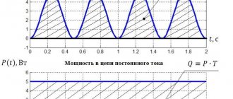
Power in an electrical circuit characterizes the intensity of energy conversion from one type to another per unit time. The unit of power is Watt (W).
For a DC circuit, source power
Pist = E I.
Receiver power
Rpr = U × I = R × I2 = U2/R
Ohm's law
This law relates to the basic provisions and concepts of electrical engineering. It most accurately reflects the relationship between quantities such as current, voltage, resistance and power. The definitions of these quantities have already been considered; now it is necessary to establish the degree of their interaction and influence on each other.
In order to calculate this or that value, you must use the following formulas:
- Current strength: I = U/R (amps).
- Voltage: U = I x R (volts).
- Resistance: R = U/I (ohm).
The dependence of these quantities, for a better understanding of the essence of the processes, is often compared with hydraulic characteristics. For example, at the bottom of a tank filled with water, a valve with a pipe adjacent to it is installed. When the valve opens, water begins to flow because there is a difference between the high pressure at the beginning of the pipe and the low pressure at the end. Exactly the same situation occurs at the ends of the conductor in the form of a potential difference - voltage, under the influence of which electrons move along the conductor. Thus, by analogy, voltage is a kind of electrical pressure.
The current strength can be compared with the water flow, that is, the amount of water flowing through the cross-section of the pipe over a set period of time. As the pipe diameter decreases, the water flow will also decrease due to increased resistance. This limited flow can be compared to the electrical resistance of a conductor, which keeps the flow of electrons within certain limits. The interaction of current, voltage and resistance is similar to hydraulic characteristics: with a change in one parameter, all the others change.
